MSG MS012 COM User manual

2021.02.16
MS012 COM
OPERATION MANUAL
ON DIAGNOSTICS OF VOLTAGE REGULATORS
INSTRUKCJA DIAGNOSTYKI
REGULATORÓW NAPIĘCIA
ИНСТРУКЦИЯ ПО ДИАГНОСТИКЕ
РЕГУЛЯТОРОВ НАПРЯЖЕНИЯ
UNIQUENESS
TRAINING
SERVICE
NNOVATION
WARRANTY
QUALITY


English
Operation manual
1
CONTENTS
INTRODUCTION ................................................................................................................................................... 2
1 TESTER DESCRIPTION..................................................................................................................................... 3
2 TESTER MENU................................................................................................................................................... 5
3 INTENDED USAGE .......................................................................................................................................... 14
3.1 Safety regulations............................................................................................................................... 15
3.2 Voltage regulator connection.......................................................................................................... 15
3.3 Voltage regulator diagnostics ......................................................................................................... 21
3.3.1 Diagnostics of voltage regulators of L/FR type .......................................................................22
3.3.2 Diagnostic of voltage regulators of RLO, RVC, C KOREA, SIG, and P-D types....................23
3.3.3 Diagnostics of voltage regulators of C JAPAN type .................................................................23
3.3.4 Diagnostics of 12/24V voltage regulators of COM type..........................................................23
Appendix 1.........................................................................................................................................................26
Appendix 2.........................................................................................................................................................69
Appendix 3......................................................................................................................................................... 72

English
tester MS012 COM
2
INTRODUCTION
The actual Operation Instruction describes the procedure of voltage regulator diagnostics with
tester MS012 COM (hereunder referred to as “the tester”) intended to detect voltage regulator
faults.
WARNING! This Instruction does not contain the description of diagnostic procedures for
all existing types of voltage regulators. If you lack knowledge and experience in diagnostics of
voltage regulators, it is advisable to take a training course at the manufacturer facility.
WARNING! MSG Equipment does not bear responsibility for any damage to the tester
resulted from its improper use.
The tester is intended for the following purposes:
1. To evaluate the voltage regulator performance under the pre-set voltage resistance and its
conformance to the technical characteristics for 12/24 voltage regulators. The diagnostics is
performed separately from the alternator. During the procedure we check the following
parameters:
- operability of the control lamp circuit;
- operability (accuracy) of the voltage setting channel;
- operability of the feedback channel (FR, DFM, P);
- stabilizing voltage;
- engine speed at which the voltage regulator switches on/off;
- load maintained by the voltage regulator.
For COM voltage regulators:
- voltage regulator ID;
- operability of the voltage regulator diagnostic system;
- type of data exchange protocol;
- data exchange rate.
2. To check the possibility of the voltage regulator installation on the alternator of a particular
vehicle based on the following criteria:
- voltage regulator performance and conformance to the technical characteristics;
- voltage regulator protocol;
- voltage regulator type and ID;
- data exchange rate.

English
Operation manual
3
1 TESTER DESCRIPTION
The front panel of the tester contains (Fig.1).
Figure 1 - Front view
1– LCD display:asensor screen where information on the voltage regulator is displayed and
through which the tester is controlled.
2– Adjustment knobs: to set up parameters for voltage regulator diagnostics:
• ELLOAD: adjustment knob with two functions: 1) to set the required resistance of the simulated
rotor in the main menu; 2) to change the load on the simulated alternator and on the tested
voltage regulator respectively, in the range from 0 to 100%.
• STATOR: adjustment knob to change frequency of stator windings displayed as engine rpm in
the range from 0 to 6000.
• VOLTAGE: adjustment knob to set the required voltage generated by the voltage regulator.
Cannot be used with terminal mode L/FR.
3– ON/OFF: button to switch the tester ON/OFF.
4– Terminals: output terminals to connect the diagnostic cables:
• В+: voltage regulator plus (terminal 30 and terminal 15);
• В-: voltage regulator minus (earth, terminal 31);
• D+: control lamp terminal used for connection to the voltage regulator terminals: D+, L, IL, 61.

English
tester MS012 COM
4
• ST1, ST2: output terminals of rotor windings of the simulated alternator to connect to the
terminals of the voltage regulator stator: P, S, STA, Stator.
• GC: output terminal to connect voltage regulator terminals: COM, SIG, and others.
• FR: load control output terminal to connect to the voltage regulator terminals: FR, DFM, M.
• F1, F2: rotor output terminals of the simulated alternator to connect to the voltage regulator
brushes or their respective terminals: DF, F, FLD.
5– USB port: a socket to connect the tester to a computer or a laptop for the purpose of
software update.
The back panel of the tester contains (Fig.2) a terminal for connection of a supply cable 1 and
a safety fuse 2.
Figure 2 – Back view
A set of 10 diagnostic cables is included in the tester set (Fig.3).
Figure 3 - Set of diagnostic cables MS0111
The color marking must be observed when connecting diagnostic cables to the tester terminals.

English
Operation manual
5
2 TESTER MENU
The main menu of the tester (Fig.4) has four buttons:
12V, 24V: buttons to select a voltage regulator by nominal voltage;
SETTINGS – button to enter menu SETTINGS;
HELP – button to enter menu HELP: a link to the actual instruction will be displayed.
Figure 4 – Main menu
Menu SETTINGS of the tester (Fig.5) contains:
Figure 5 – Menu SETTINGS
• «Inverse encoder rotation»: a click on the checkbox will reverse the order of changing
parameters with adjustment knobs EL LOAD, STATOR, and VOLTAGE - the values will
increase/decrease in the reverse direction.
• Disable sound: click on the checkbox or rotate the knobs to mute.
• Manual control B+: menu setting used for the tester calibration by a maintenance service
specialist.

English
tester MS012 COM
6
• CALIBRATION: button to enter the tester calibration menu. This menu is meant exclusively for
calibration of the device by specialists from the manufacturing facility.
WARNING! Customers are not allowed to make any changes to the tester calibration.
Current software version is displayed in the bottom right corner of menu screen SETTINGS.
The resistance value of the simulated rotor, displayed below buttons 12V and 24V, is set with
adjustment knob EL LOAD in the following range:
•from 1.8 to 22 Ohm for 12V;
•from 4.1 to 22 Ohm for 24V.
Press button 12V or 24V to enter the menu for selection of the voltage regulator type (Fig.6
and 7):
Figure 6 – Menu to select the type of the tested voltage regulator
with nominal voltage of 12V
Figure 7 – Menu to select the type of the tested voltage regulator
with nominal voltage of 24V

English
Operation manual
7
Press the button one time to select the voltage regulator type. The selected type will light up.
There are only two options for 24V voltage regulators: L/FR or COM (LIN).
The type selection menu has three buttons:
• BACK: return to the main menu;
• HELP: reference information on the terminals for connection of the selected voltage
regulator type;
• TEST: activation of a test mode for the selected voltage regulator type.
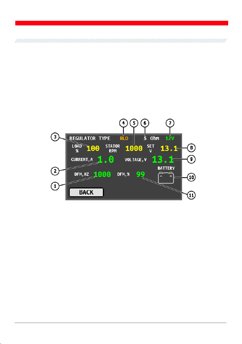
On activation of the test mode for RLO, RVC, and C KOREA voltage regulators, the following
information will be displayed (Fig.8):
Figure 8 – Menu screen for testing voltage regulators of RLO, RVC, and C KOREA types
1 – signal frequency through FR channel;
2 – voltage regulator measured current applied to the stator winding of the alternator;
3 – pre-set (simulated) load on the voltage regulator;
4 – voltage regulator type;
5 – pre-set engine rpms;
6 – pre-set rotor resistance;
7 – voltage regulator nominal voltage;
8 – pre-set stabilizing voltage;
9 – measured stabilizing voltage;
10 – control lamp indication;
11 – PWM signal waveform through FR channel.
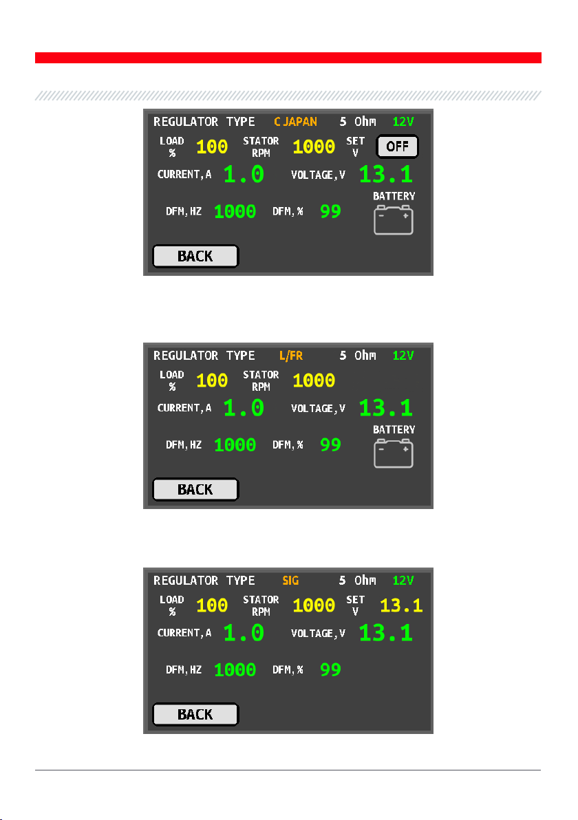
OFF displayed on the screen instead of the pre-set voltage value when testing voltage regulators
of C JAPAN type, means the operating mode is set for regulators with voltage of 12.1-12,7V. Press
OFF one time to switch to the operating mode for voltage regulators with the voltage of 14-14,4V.
ON will appear on the screen.

English
tester MS012 COM
8
Figure 9 – Diagnostic screen for voltage regulators of C JAPAN type
The pre-set voltage won’t be displayed on the diagnostic screen for voltage regulators of L/FR
type (Fig.10).
Figure 10 – Diagnostic screen for 12/24V voltage regulators of L/FR type
The diagnostic screen for voltage regulators of SIG and P-D types has no control lamp indication
(Fig.11)
Figure 11 – Diagnostic screen for voltage regulators of SIG and P-D types

English
Operation manual
9
The following information will be displayed on the diagnostic screen for 12V voltage regulators
of COM type (Fig.12):
Figure 12 – Diagnostic screen for 12V voltage regulators of COM type
LIN STATUS – voltage regulator connection status.
PROTOCOL – voltage regulator protocol type (BSS, LIN1, or LIN2).
SPEED – COM voltage regulator data exchange rate under protocol LIN. The following speed
values can be displayed:
• «L» – 2400 Baud (low);
• «M» – 9600 Baud (medium);
• «H» – 19200 Baud (high).
EXCITATION – stator excitation level (%).
ID – voltage regulator identification number. By this number, the engine electronic control unit
identifies the alternator type.
TYPE – type of the voltage regulator operating under protocol LIN is displayed as one of the
following codes: A1, A2, A3, A4, B1, B2, B3, B4, C3, D1, D2, E1.
ERRORS – indicator of errors transmitted to the engine ECU by the voltage regulator. Error types:
• EL – electrical error;
• MEC – mechanical error;
• TH – thermal error.
SUPPLIER – voltage regulator manufacturer.
SUPP. ID – voltage regulator identification number assigned by the manufacturer.
BACK – test mode exit.

English
tester MS012 COM
10
The following information will be displayed on the diagnostic screen for 24V voltage regulators
of COM type (Fig.13):
Figure 13 –Diagnostic screen for 24V voltage regulators of COM type
COM SPEED - rate of data exchange between a voltage regulator and a vehicle ECU.
B+ - measured voltage across terminal B+.
TEMPERATURE - voltage regulator self-measured temperature.
I FIELD - current load on brushes set by the voltage regulator.
SET U - stabilizing voltage rated by the voltage regulator
3 INTENDED USAGE
1. The tester is intended for indoor use. Consider the environmental conditions and technical
characteristics of the tester set out in article 2 of User Manual when using the device outdoors.
Avoid spilling liquids on the tester.
2. Do not interfere with the electric circuit of the tester to avoid damage to the device. In case
of malfunction, contact the technical support service or sales representative.
3.1 Safety regulations
1. The device operation requires special qualification of the operator. Only the persons who have
attended a safety briefing and obtained a special permit to operate certain types oftest benches
(devices) are qualified to work with the equipment.
2. Make sure that measuring cable clips do not have insulation damage or bare metal spots.
Inspect the clips for breaks. In case of visible damage, replace the clips before launching the
equipment.

English
Operation manual
11
3.2 Voltage regulator connection
A proper connection of the voltage regulator to the diagnostic terminals of the tester is
necessary for evaluation of the regulator performance.
WARNING! To avoid damage to the tester or its failure, extra care is to be taken when
connecting the cable clips to the contacts inside the terminals. The cable clips must be
completely insulated (Fig.14).
Figure 14 -Connection of the cable clips to the contacts inside the terminal
Search online the information on the terminals marking by the voltage regulator part number.
You may also find information on connection of the most common voltage regulator types in
Appendix 3 of the actual Operation Instruction.
The diagram for connection of voltage regulator ARE1054 is shown as an example in Figure 15.
Figure 15. Voltage regulator ARE1054

English
tester MS012 COM
12
Identify the voltage regulator type by its connection terminals shown in Figure15 and using the
information set out in Appendices 1, 2. In the example given, these are terminals DFM and L(RVC)
(can be marked as L(PWM)). Terminal DFM cannot be used for identification of the voltage
regulator type, while we can identify it as RVC-type by terminal L(RVC).
Then we refer to Appendix 1 to determine the tester terminals for connection of the voltage
regulator (Fig.16). Table 1 and Figure 16 show the diagram for connection of voltage regulator
ARE1054.
Table 1 – Connection of voltage regulator ARE1054 to the tester
Voltage regulator
terminal
Tester output terminal
Color marking of
cable
DFM
FR
yellow
L(RVC)
GC
yellow
Ps
ST1
blue
B+
B+
red
DF
F1
green
F2
green
B-
B-
black
Figure 16 – Voltage regulator ARE1054 connected to the tester output terminals

English
Operation manual
13
Figure 17 shows a diagram of voltage regulator ARE6076 connection as an example.
Figure 17 – Voltage regulator ARE6076
Voltage regulator type can be identified by its connection terminals and using the information
set out in Appendices 1, 2. In this case, we cannot identify the voltage regulator type by terminals
IG, S, and FR(M), while it can be identified as L/FR by terminal L.
Then we refer to Appendix 1 to determine the tester terminals for connection of the voltage
regulator. Table 2 and Figure 18 show the diagram for connection of the voltage regulator to the
tester.
Table 2 – Connection of voltage regulator ARE6076 to the tester
Voltage regulator
terminal
Tester output
terminal
Color marking of
cable
IG
IG
red
L
D+
black
S
S
blue
FR(M)
FR
yellow
B+
B+
red
F2
green
F
F1
green
Ps
ST1
blue
GND
B-
black

English
tester MS012 COM
14
Figure 18 – Diagram of voltage regulator ARE6076 connection to the tester
Connection of voltage regulator ARE6076 has some specifics:
Firstly, the voltage regulator must be connected to three output terminals B+ while the tester
has only two. The problem can be solved by connecting a spare blue cable to one of the red
cables supplied with a special socket connector which substitutes the missing terminal of the
tester (Fig.19).
Figure 19 – Connection of additional cable B+

English
Operation manual
15
Secondly, there are two cables - F1 and F2, both of which must be connected to the voltage
regulator brushes or their respective terminals. Figure 17 shows only one terminal – F, to which
cable F1 must be connected. The other green cable (F2) must be connected to terminal B+, since
one of the brushes is permanently connected to B+ while the excitation winding is controlled
through the brush connected to the alternator negative terminal (A-circuit type).
Figure 20 shows the connection diagram of voltage regulator ARE6149P as an example.
Figure 20 – Voltage regulator ARE6149P
Voltage regulator type should be identified by its connection terminals and using the
information set out in Appendices 1, 2. In this case, there is only one terminal – LIN, that
identifies this voltage regulator as COM type.
Then we refer to Appendix 1 to determine the tester terminals for connection of the voltage
regulator. Table 3 and Figure 21 show the diagram for connection of the voltage regulator
ARE6149P to the tester.
Table 3 – Connection of voltage regulator ARE6149P to the tester
Voltage regulator
terminal
Tester output
terminal
Color marking
of cable
B+
B+
red
F
F1
green
Ps
ST1
blue
LIN
GC
yellow
G
B-
black
F2
green

English
tester MS012 COM
16
Figure 21. Voltage regulator ARE6149P connected to the tester terminals
Connection of voltage regulator ARE6149P has a special aspect. Figure 20 shows only one
terminal – F, for connection of cable F1. The other cable – F2 must be connected to terminal B-.
Consequently, one of the brushes is permanently connected to B- of the alternator, while the
excitation winding is controlled through terminal B+.
3.3 Voltage regulator diagnostics
Before launching the diagnostic procedure, set up the resistance of the stator winding in the
main menu (Fig.4) with adjustment knob EL LOAD. In case, the resistance value of the stator
winding is known, set this (measured) value. If the resistance value is not known, set it as follows:
• 5 Ohm for 12V;
• 22 Ohm for 24V.
The common diagnostic procedure for a majority of voltage regulators is as follows:
1) Connect the voltage regulator to the tester output terminals.
2) Set up the resistance of the stator winding.
3) Select the nominal voltage of the tested voltage regulator.
4) Select the type of the tested voltage regulator.
5) Evaluate the control lamp behavior: red indication must be on when the speed is below
700 rpm, the indication must turn white (off) when the speed is above 800-1200 rpm.
6) Evaluate the voltage regulator response to the load change set with adjustment knob EL LOAD.

English
Operation manual
17
7) Evaluate the voltage regulator ability to adjust to the stabilizing voltage set with knob
VOLTAGE.
WARNING! The selected test mode (Fig. 6, 7) must correspond to the voltage regulator type.
3.3.1 Diagnostics of voltage regulators of L/FR type
1. Connect the voltage regulator to the tester as described in article 3.2 of the actual Instruction.
2. In the main menu (Fig.4) select the nominal voltage of the tested voltage regulator: 12V or 24V.
3. Rotate adjustment knob STATOR to set the stator speed “STATOR RPM” at 0 – red indication of
the control lamp must be on. Then, set the stator speed at over 1000 rpm – the control lamp
indication must turn white now. The displayed voltage value “VOLTAGE, V” must set in the range
of 14V-14.8V for 12V regulators, 26,5 – 29V for 24V regulators and correspond to the voltage
regulator characteristics.
4. Rotate adjustment knob “EL LOAD” to change the value (%) from 10 to 100%. The value in box
“CURRENT, A” must vary with it.
5. Failure to perform as described in articles 3-4 of the Instruction signals the voltage regulator
malfunction.
6. Press BACK to exit the test mode. Disconnect the cable clips from the voltage regulator.
3.3.2 Diagnostic of voltage regulators of RLO, RVC, C
KOREA, SIG, and P-D types
1. Connect the voltage regulator to the tester as described in article 3.2 of the actual Instruction.
2. In the main menu (Fig.4) select the nominal voltage of the tested voltage regulator: 12V.
3. In the menu for selection of a voltage regulator by type (Fig.6), select the voltage regulator
terminal and press TEST. The tester will enter the test mode.
4*. Rotate adjustment knob “STATOR” to set the stator speed “STATOR RPM” at 0 – red indication
of the control lamp must be on. Then, set the stator speed at over 1000 rpm – the control lamp
indication must turn white now.
* The procedure does not apply to voltage regulators of SIG and P-D types.
5. Rotate “EL LOAD” to set the value at 100%.
6. Rotate adjustment knob “STATOR” to set the stator speed “STATOR RPM” in the range from
2000 to 6000 rpm. Change the pre-set voltage “SET V” in the range of 13.1-14.5V. The value in box
“VOLTAGE, V” varies in proportion to it.

English
tester MS012 COM
18
7. Rotate adjustment knobs “EL LOAD” to change the value in the range from 10 to 100%. The
value in box “CURRENT, A” varies in proportion with it.
8. The measured DFM signal will be displayed in boxes “DFM, Hz” and “DFM, %”.
8.1 If these values are displayed as follows: DFM, Hz – “NA”, DFM, % – “HI”, it means either the
feedback channel is inoperable or one of those terminals FR, DFM, М, LI is missing in the voltage
regulator.
9. Failure to perform as described in article 4* - 8 of the Instruction signals the voltage regulator
malfunction.
10. Press BACK to exit the test mode. Disconnect the cable clips from the voltage regulator.
3.3.3 Diagnostics of voltage regulators of C JAPAN type
1. Connect the voltage regulator to the tester as described in article 3.2 of the actual Instruction.
2. In the main menu (Fig.4) select the nominal voltage of the tested voltage regulator: 12V.
3. In the menu for selection a voltage regulator by type (Fig.6), select the voltage regulator
terminal and press TEST. The tester will enter the test mode.
4. Rotate adjustment knob “STATOR” to set the stator speed “STATOR RPM” at 0 – red indication
of the control lamp must be on. Then set the stator speed at over 1000 rpm – the control lamp
indication must turn white now. The displayed voltage value “VOLTAGE, V” must set in the range
of 12V to 12,7V.
5. Rotate adjustment knob EL LOAD to set the value at 100%.
6. Press OFF, the value in box “VOLTAGE, V” must set in the range of 14-14,4V. Button ON will
appear on the screen.
7. Rotate adjustment knob EL LOAD to change the value in the range from 10 to 100%. The value
in box “CURRENT, A” must vary in proportion with it.
8. Measured values of DFM signal must be displayed in boxes “DFM, Hz” and “DFM, %”.
8.1 If these values are displayed as follows: DFM, Hz – “NA”, DFM, % – “HI”, it means either the
feedback channel is inoperable or one of those terminals FR, DFM, М, LI is missing in the voltage
regulator.
9. Failure to perform as described in articles 4-8 of the actual Operation Instruction signals the
voltage regulator malfunction.
10. Press BACK to exit the test mode. Disconnect the cable clips from the voltage regulator.
Other manuals for MS012 COM
2
Table of contents
Languages:
Other MSG Test Equipment manuals