MSI A320M PRO-C User manual

1
Contents
Contents
2
3
6
7
LAN Port LED Status Table........................................................................................7
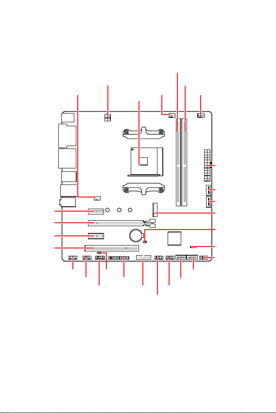
8
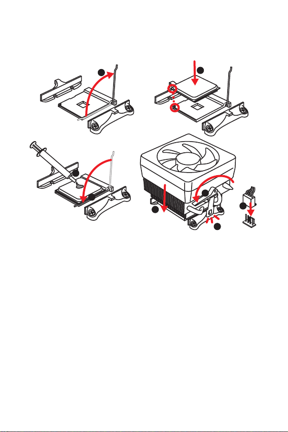
CPU Socket.................................................................................................................9
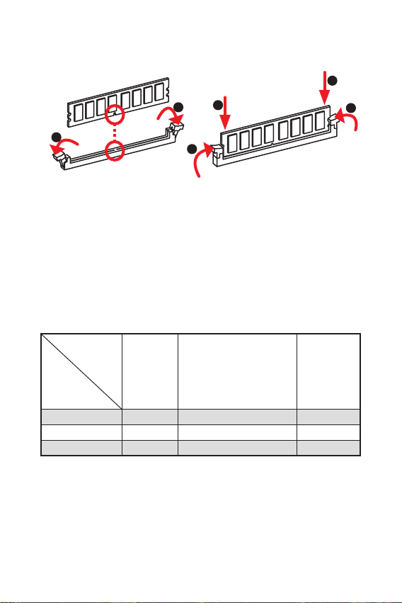
DIMM Slots................................................................................................................10
PCI_E1~3 & PCI1: PCIe & PCI Expansion Slots .......................................................10
JFP1, JFP2: Front Panel Connectors.......................................................................11
SATA1~4: SATA 6Gb/s Connectors...........................................................................12
M2_1: M.2 Slot (Key M).............................................................................................12
ATX_PWR1, CPU_PWR1: Power Connectors...........................................................13
JUSB1~2: USB 2.0 Connectors.................................................................................14
JUSB3: USB 3.2 Gen1 Connector .............................................................................14
CPU_FAN1, SYS_FAN1~2: Fan Connectors.............................................................15
JLPT1: Parallel Port Connector...............................................................................15
JTPM1: TPM Module Connector...............................................................................16
JCI1: Chassis Intrusion Connector...........................................................................16
JAUD1: Front Audio Connector ................................................................................17
JCOM1: Serial Port Connector.................................................................................17
JBAT1: Clear CMOS (Reset BIOS) Jumper...............................................................17
18
Entering BIOS Setup.................................................................................................18
Resetting BIOS..........................................................................................................19
Updating BIOS...........................................................................................................19
20
Installing Windows®10..............................................................................................20
Installing Drivers......................................................................................................20
Installing Utilities .....................................................................................................20
Thank you for purchasing the MSI®mother-
board. This User Guide gives information about board layout,
component overview, BIOS setup and software installation.

2
The components included in this package are prone to damage from electrostatic
discharge (ESD). Please adhere to the following instructions to ensure successful
computer assembly.
Ensure that all components are securely connected. Loose connections may cause
the computer to not recognize a component or fail to start.
Hold the motherboard by the edges to avoid touching sensitive components.
It is recommended to wear an electrostatic discharge (ESD) wrist strap when
handling the motherboard to prevent electrostatic damage. If an ESD wrist strap is
not available, discharge yourself of static electricity by touching another metal object
before handling the motherboard.
Store the motherboard in an electrostatic shielding container or on an anti-static
pad whenever the motherboard is not installed.
Before turning on the computer, ensure that there are no loose screws or metal
components on the motherboard or anywhere within the computer case.
Do not boot the computer before installation is completed. This could cause
permanent damage to the components as well as injury to the user.
If you need help during any installation step, please consult a certified computer
technician.
Always turn off the power supply and unplug the power cord from the power outlet
before installing or removing any computer component.
Keep this user guide for future reference.
Keep this motherboard away from humidity.
Make sure that your electrical outlet provides the same voltage as is indicated on
the PSU, before connecting the PSU to the electrical outlet.
Place the power cord such a way that people can not step on it. Do not place
anything over the power cord.
All cautions and warnings on the motherboard should be noted.
If any of the following situations arises, get the motherboard checked by service
personnel:
Liquid has penetrated into the computer.
The motherboard has been exposed to moisture.
The motherboard does not work well or you can not get it work according to
user guide.
The motherboard has been dropped and damaged.
The motherboard has obvious sign of breakage.
Do not leave this motherboard in an environment above 60°C (140°F), it may
damage the motherboard.

3
Supports 1st, 2nd and 3rd Gen AMD®Ryzen™, Ryzen™ with
Radeon™ Vega Graphics, 2nd Gen AMD®Ryzen™ with Radeon™
Graphics, Athlon™ with Radeon™ Vega Graphics, A-series and
Athlon™ X4 Desktop Processors for Socket AM4
AMD® A320 chipset
2x DDR4 memory slots, support up to 32GB*
Supports 1866/ 2133/ 2400/ 2667 Mhz (by JEDEC)
Supports 2667/ 2800/ 2933/ 3000/ 3066/ 3200 Mhz (by
A-XMP OC mode)
Dual channel memory architecture
Supports ECC UDIMM memory (non-ECC mode)
Support non-ECC UDIMM memory
* Please refer www.msi.com for more information on
compatible memory.
1x PCIe 3.0 x16 slot
Supports x16 speed
1st, 2nd and 3rd Gen AMD RyzenTM
Supports x8 speed
Ryzen™ with Radeon™ Vega Graphics
2nd Gen AMD Ryzen™ with Radeon™ Graphics
A-series
AthlonTM X4
Supports x4 speed
AMD®Athlon™ with Radeon™ Vega Graphics
2x PCIe 2.0 x1 slots
1x PCI slot
1x VGA port, supports a maximum resolution of
2048x1280 @60Hz, 1920x1200 @60Hz*
1x DVI-D port, supports a maximum resolution of
1920x1200 @60Hz*
1x HDMI™ 1.4 port, supports a maximum resolution of
4096x2160 @24Hz*
* Only support when using the processor with Graphics
* Maximum shared memory of 2048 MB
Continued on next page

4
Continued from previous page
AMD® A320 Chipset
4x SATA 6Gb/s ports
Supports RAID 0, RAID1 and RAID 10
1x M.2 slot (Key M)
Supports PCIe 3.0 x4 and SATA 6Gb/s
1st, 2nd and 3rd Gen AMD RyzenTM
Ryzen™ with Radeon™ Vega Graphics
2nd Gen AMD Ryzen™ with Radeon™ Graphics
Supports PCIe 3.0 x2 and SATA 6Gb/s
AMD®Athlon™ with Radeon™ Vega Graphics
A-series
AthlonTM X4
Supports 2242/ 2260/ 2280 storage devices
Realtek®ALC892 Codec
7.1-Channel High Definition Audio
LAN 1x Realtek®8111H Gigabit LAN controller
6x USB 3.2 Gen1 (SuperSpeed USB) ports (4 ports on
the back panel, 2 ports available through the internal USB
connector)
6x USB 2.0 (High-speed USB) ports (2 ports on the back
panel, 4 ports available through the internal USB connectors)
NUVOTON NCT6797 Controller Chip
CPU/System temperature detection
CPU/System fan speed detection
CPU/System fan speed control
m-ATX Form Factor
9.6 in. x 9.6 in. (24.4 cm x 24.4 cm)
1x 256 Mb flash
UEFI AMI BIOS
Multi-language
Continued on next page

5
Continued from previous page
1x PS/2 mouse port
1x PS/2 keyboard port
1x VGA port
1x DVI-D port
1x COM port
1x HDMI™ port
4x USB 3.2 Gen1 Type-A ports
1x LAN (RJ45) port
2x USB 2.0 Type-A ports
3x audio jacks
1x 24-pin ATX main power connector
1x 4-pin ATX 12V power connector
4x SATA 6Gb/s connectors
2x USB 2.0 connectors (supports additional 4 USB 2.0 ports)
1x USB 3.2 Gen1 connector (supports additional 2 USB 3.2
Gen1 ports)
1x 4-pin CPU fan connector
2x 4-pin system fan connector
1x Front panel audio connector
2x Front panel connectors
1x TPM module connector
1x Chassis Intrusion connector
1x Serial port connector
1x Parallel port connector
1x Clear CMOS jumper
Drivers
COMMAND CENTER
LIVE UPDATE 6
SMART TOOL
X-BOOST
Norton™Security
Google Chrome™,Google Toolbar, Google Drive
CPU-Z MSI GAMING

6
Please check the contents of your motherboard package. It should contain:
Motherboard
Driver DVD
Quick Installation Guide
I/O Shielding
SATA 6G Cable x2
Case Badge
Product registration card
M.2 Screw x1
If any of the above items are damaged or missing, please contact your retailer.
The package contents may vary according to the model you purchased.

7
Off No link
Yellow Linked
Blinking Data activity
Off 10 Mbps connection
Green 100 Mbps connection
Orange 1 Gbps connection
To configure 7.1-channel audio, you have to connect front audio I/O module to JAUD1
connector and follow the below steps.
Click on the to open the dialog
below.
Select .
Plug your speakers to audio jacks on rear and front I/O panel. When you plug into
a device at an audio jack, a dialogue window will pop up asking you which device
is current connected.
PS/2 Mouse LAN
USB 3.2 Gen1
USB 2.0
PS/2 Keyboard DVI-D
VGA COM Line-in
Line-out
Mic in

8
BAT1
CPU_FAN1
CPU Socket
SYS_FAN1 SYS_FAN2
PCI_E2
PCI_E3
PCI1
PCI_E1
DIMMA1
DIMMB1
JFP2
JBAT1
M2_1
JFP1
SATA1JAUD1
ATX_PWR1
CPU_PWR1
SATA3
SATA4
JUSB3 JUSB1
JUSB2
JTPM1
SATA2
JLPT1
JCI1
JCOM1

9
Please install the CPU into the CPU socket as shown below.
BIOS to default values due to the AM4 processor’s architecture.
Always unplug the power cord from the power outlet before installing or removing
the CPU.
When installing a CPU, always remember to install a CPU heatsink. A CPU heatsink
is necessary to prevent overheating and maintain system stability.
your system.
Overheating can seriously damage the CPU and motherboard. Always make sure
the cooling fans work properly to protect the CPU from overheating. Be sure to apply
an even layer of thermal paste (or thermal tape) between the CPU and the heatsink to
enhance heat dissipation.
If you purchased a separate CPU and heatsink/ cooler, Please refer to the docu-
mentation in the heatsink/ cooler package for more details about installation.
1
3
5
4
6
7
8
2

10
Please install the memory module into the DIMM slot as shown below.
Due to chipset resource usage, the available capacity of memory will be a little less
than the amount of installed.
-
gested to protect the processor.
of memory modules may operate lower than the marked value under the default
state. Please refer www.msi.com for more information on compatible memory.
unplug the power supply power cable from the power outlet. Read the expansion
card’s documentation to check for any necessary additional hardware or software
changes.
If you install a large and heavy graphics card, you need to use a tool such as MSI
Gaming Series Graphics Card Bolster to support its weight to prevent deformation
of the slot.
PCI slot does not support the function of PCI wake up on LAN.
Processors
Slots
1st, 2nd
and 3rd
Gen AMD
RyzenTM
Ryzen™ with Radeon™ Vega
Graphics,
2nd Gen AMD Ryzen™ with
Radeon™ Graphics,
A-series,
AthlonTM X4
Athlon™ with
Radeon™
Vega Graphics
PCI_E1 PCIe 2.0 x1 PCIe 2.0 x1 PCIe 2.0 x1
PCI_E2 PCIe 3.0 x16 PCIe 3.0 x8 PCIe 3.0 x4
PCI_E3 PCIe 2.0 x1 PCIe 2.0 x1 PCIe 2.0 x1
1
12
3
3
2

11
These connectors connect to the switches and LEDs on the front panel.
1
2 10
9
+
+
+- --
-
+
Power LED
HDD LED Reset Switch
Reserved
Power Switch 1 HDD LED + 2 Power LED +
3 HDD LED - 4 Power LED -
5 Reset Switch 6 Power Switch
7 Reset Switch 8 Power Switch
9 Reserved 10 No Pin
JFP2 1
+
+-
-
Speaker
Buzzer 1 Speaker - 2 Buzzer +
3 Buzzer - 4 Speaker +
HDD LED
RESET SW
HDD LED HDD LED -
HDD LED +
POWER LED -
POWER LED +
POWER LED
JFP1

12
Please install the M.2 solid-state drive (SSD) into the M.2 slot as shown below.
These connectors are SATA 6Gb/s interface ports. Each connector can connect to one
SATA device.
SATA2
SATA1 SATA3
SATA4
Please do not fold the SATA cable at a 90-degree angle. Data loss may result
during transmission otherwise.
SATA cables have identical plugs on either sides of the cable. However, it is
saving purposes.
1
3
Standoff
Supplied
M.2 screw 30º30º
2

13
These connectors allow you to connect an ATX power supply.
Make sure that all the power cables are securely connected to a proper ATX power
supply to ensure stable operation of the motherboard.
24
131
12
ATX_PWR1
1 +3.3V 13 +3.3V
2 +3.3V 14 -12V
3 Ground 15 Ground
4 +5V 16 PS-ON#
5 Ground 17 Ground
6 +5V 18 Ground
7 Ground 19 Ground
8 PWR OK 20 Res
9 5VSB 21 +5V
10 +12V 22 +5V
11 +12V 23 +5V
12 +3.3V 24 Ground
3
2 1
4CPU_PWR1
1 Ground 5 +12V
2 Ground 6 +12V
3 Ground 7 +12V
4 Ground 8 +12V

14
This connector allows you to connect USB 3.2Gen1 ports on the front panel.
1 10
1120
1 Power 11 USB2.0+
2 USB3_RX_DN 12 USB2.0-
3 USB3_RX_DP 13 Ground
4 Ground 14 USB3_TX_C_DP
5 USB3_TX_C_DN 15 USB3_TX_C_DN
6 USB3_TX_C_DP 16 Ground
7 Ground 17 USB3_RX_DP
8 USB2.0- 18 USB3_RX_DN
9 USB2.0+ 19 Power
10 Ground 20 No Pin
Note that the Power and Ground pins must be connected correctly to avoid possible
damage.
These connectors allow you to connect USB 2.0 ports on the front panel.
Note that the VCC and Ground pins must be connected correctly to avoid possible
damage.
In order to recharge your iPad,iPhone and iPod through USB ports, please install
MSI®SUPER CHARGER utility.
1
2 10
9
1 VCC 2 VCC
3 USB0- 4 USB1-
5 USB0+ 6 USB1+
7 Ground 8 Ground
9 No Pin 10 NC

15
PWM Mode fan connectors provide constant 12V output and adjust fan speed with
speed control signal. When you plug a 3-pin (Non-PWM) fan to a fan connector in
PWM mode, the fan speed will always maintain at 100%, which might create a lot of
noise.
You can adjust fan speed in
1 Ground 2 +12V
3 Sense 4 Speed Control Signal
1
SYS_FAN1~2
1
CPU_FAN1
1
2 26
25
1 RSTB# 2 AFD# 3 PRND0
4 ERR# 5 PRND1 6 PINIT#
7 PRND2 8 LPT_SLIN# 9 PRND3
10 Ground 11 PRND4 12 Ground
13 PRND5 14 Ground 15 PRND6
16 Ground 17 PRND7 18 Ground
19 ACK# 20 Ground 21 BUSY
22 Ground 23 PE 24 Ground
25 SLCT 26 No Pin
This connector allows you to connect the optional parallel port with bracket.

16
This connector is for TPM (Trusted Platform Module). Please refer to the TPM
security platform manual for more details and usages.
1
2 14
13
1 LPC Clock 2 3V Standby power
3 LPC Reset 4 3.3V Power
5 LPC address & data pin0 6 Serial IRQ
7 LPC address & data pin1 8 5V Power
9 LPC address & data pin2 10 No Pin
11 LPC address & data pin3 12 Ground
13 LPC Frame 14 Ground
This connector allows you to connect the chassis intrusion switch cable.
Normal
(default) Trigger the chassis
intrusion event
Connect the connector to the chassis intrusion switch/ sensor on the
chassis.
Close the chassis cover.
Go to .
Set to .
Press F10 to save and exit and then press the key to select .
Once the chassis cover is opened again, a warning message will be displayed on
screen when the computer is turned on.
Go to .
Set to Reset.
Press to save and exit and then press the key to select .

17
This connector allow you to connect audio jacks on the front panel.
1
2 10
9
1 MIC L 2 Ground
3 MIC R 4 NC
5 Head Phone R 6 MIC Detection
7 SENSE_SEND 8 No Pin
9 Head Phone L 10 Head Phone Detection
This connector allows you to connect the optional serial port with bracket.
1
2 10
9
1 DCD 2 SIN
3 SOUT 4 DTR
5 Ground 6 DSR
7 RTS 8 CTS
9 RI 10 No Pin
There is CMOS memory onboard that is external powered from a battery located on
the motherboard to save system configuration data. If you want to clear the system
configuration, set the jumpers to clear the CMOS memory.
Keep Data
(default) Clear CMOS/ Reset
BIOS
Power off the computer and unplug the power cord.
Use a jumper cap to short JBAT1 for about 5-10 seconds.
Remove the jumper cap from JBAT1.
Plug the power cord and power on the computer.

18
The default settings offer the optimal performance for system stability in normal
conditions. You should to avoid possible system
damage or failure booting unless you are familiar with BIOS.
BIOS items are continuous update for better system performance. Therefore, the
reference only. You could also refer to the HELP information panel for BIOS item
description.
The BIOS items will vary with the processor.
Press key, when the
message appears on the screen during the boot process.
F1: General Help
F2: Add/ Remove a favorite item
F3: Enter Favorites menu
F4: Enter CPU Specifications menu
F5: Enter Memory-Z menu
F6: Load optimized defaults
F7: Switch between Advanced mode and EZ mode
F8: Load Overclocking Profile
F9: Save Overclocking Profile
F10: Save Change and Reset*
F12: Take a screenshot and save it to USB flash drive (FAT/ FAT32 format only).
: Enter Search page
* When you press F10, a confirmation window appears and it provides the
modification information. Select between Yes or No to confirm your choice.

19
You might need to restore the default BIOS setting to solve certain problems. There
are several ways to reset BIOS:
Go to BIOS and press F6 to load optimized defaults.
Short the jumper on the motherboard.
Please refer to the jumper section for resetting BIOS.
Before updating:
Please download the latest BIOS file that matches your motherboard model from MSI
website. And then save the BIOS file into the USB flash drive.
Updating BIOS:
Insert the USB flash drive that contains the update file into the USB port.
Please refer the following methods to enter flash mode.
Reboot and press key during POST and click on to reboot the
system.
Reboot and press key during POST to enter BIOS. Click the
button and click on to reboot the system.
Select a BIOS file to perform the BIOS update process.
After the flashing process is 100% completed, the system will reboot
automatically.
Before updating:
Make sure the LAN driver is already installed and the Internet connection is set
properly.
Updating BIOS:
Install and launch MSI LIVE UPDATE 6.
Select .
Click on Scan button.
Click on icon to download and install the latest BIOS file.
Click Next and choose . And then click Next and to start
updating BIOS.
After the flashing process is 100% completed, the system will restart
automatically.

20
Please download and update the latest utilities and drivers at www.msi.com
®
Power on the computer.
Insert the Windows®10 installation disc/USB into your computer.
Press the button on the computer case.
Press F11 key during the computer POST (Power-On Self Test) to get into Boot
Menu.
Select the Windows®10 installation disc/USB from the Boot Menu.
Press any key when screen shows
message.
Follow the instructions on the screen to install Windows®10.
Start up your computer in Windows®10.
Insert MSI®Driver Disc into your optical drive.
Click the pop-up notification,
then select to open the installer. If you turn off the AutoPlay
feature from the Windows Control Panel, you can still manually execute the
from the root path of the MSI Driver Disc.
The installer will find and list all necessary drivers in the tab.
Click the button in the lower-right corner of the window.
The drivers installation will then be in progress, after it has finished it will prompt
you to restart.
Click button to finish.
Restart your computer.
Before you install utilities, you must complete drivers installation.
Open the installer as described above.
Click the tab.
Select the utilities you want to install.
Click the button in the lower-right corner of the window.
The utilities installation will then be in progress, after it has finished it will
prompt you to restart.
Click button to finish.
Restart your computer.
Table of contents
Languages:
Other MSI Motherboard manuals

MSI
MSI B450M PRO-M2 V2 User manual

MSI
MSI MS-9641 User manual

MSI
MSI H310M PRO-VH User manual

MSI
MSI 990XA-GD55 series User manual

MSI
MSI PRO B660M-A WIFI DDR4 User manual

MSI
MSI MS-7255 User manual

MSI
MSI MS-6189 User manual

MSI
MSI MS-9125 User manual

MSI
MSI 865PE/G Neo2-P MS-6728 User manual

MSI
MSI 870S-C45 Series User manual

MSI
MSI MS-6104 User manual

MSI
MSI MPG Z690 CARBON WIFI User manual

MSI
MSI X58A-GD45 series User manual

MSI
MSI MAG B550M BAZOOKA User manual

MSI
MSI A320M PRO-M2 V2 User manual

MSI
MSI Z790 GAMING PLUS WIFI User manual

MSI
MSI B450M MORTAR TITANIUM User manual

MSI
MSI P4M900M3-L User manual

MSI
MSI B450 TOMAHAWK MAX User manual

MSI
MSI MEG Series User manual