MSI B760M GAMING PLUS WIFI User manual

B760M GAMING PLUS WIFI
Motherboard
User Guide

2
Contents
Quick Start..................................................................................................................... 4
Specifications.............................................................................................................. 16
Special Features......................................................................................................... 20
Package Contents ...................................................................................................... 21
Back Panel Connectors ............................................................................................. 22
LAN Port LED Status Table .................................................................................. 23
Audio Jacks Connection ....................................................................................... 23
Installing antennas............................................................................................... 25
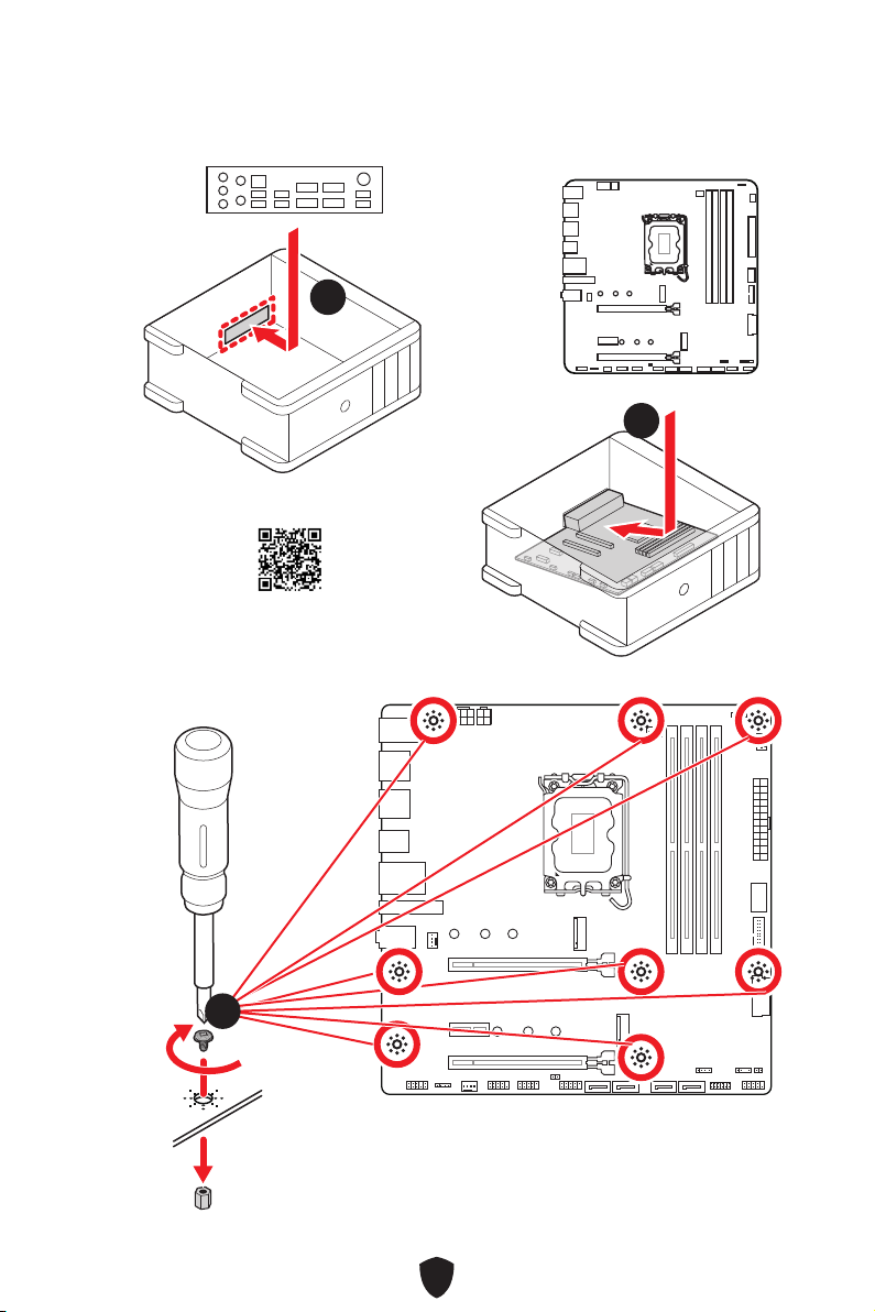
Overview of Components........................................................................................... 26
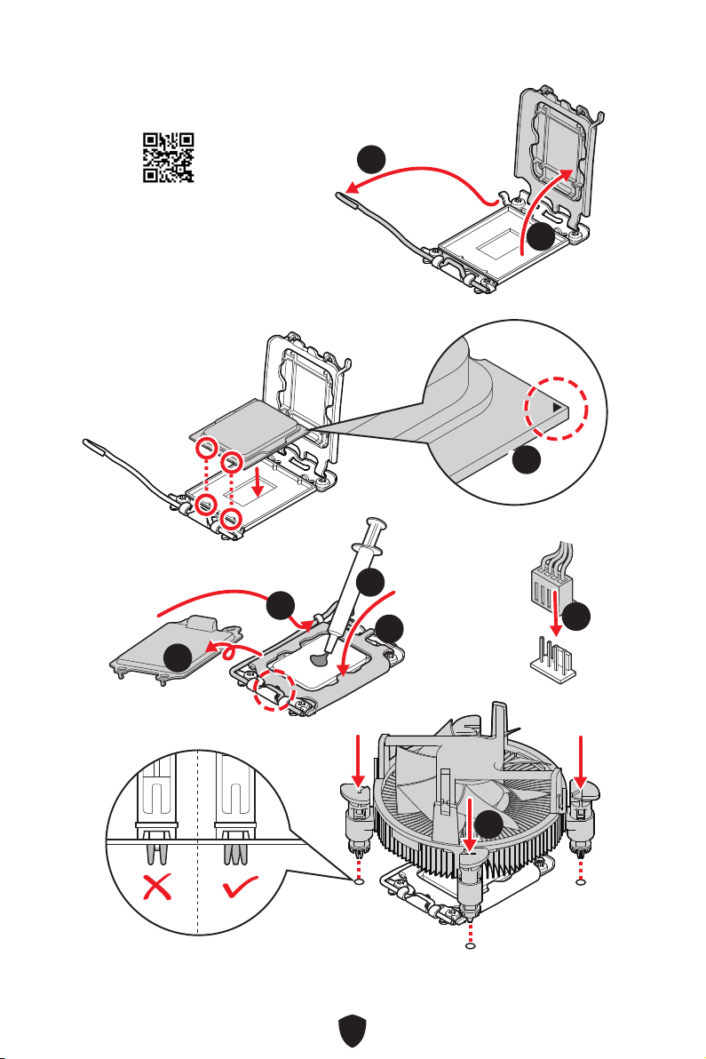
CPU Socket ........................................................................................................... 27
DIMM Slots............................................................................................................ 28
PCI_E1~3: PCIe Expansion Slots.......................................................................... 29
M2_1~2: M.2 Slots (Key M) ................................................................................... 30
SATA_5~8: SATA 6Gb/s Connectors..................................................................... 33
JAUD1: Front Audio Connector ............................................................................ 33
JFP1, JFP2: Front Panel Connectors................................................................... 34
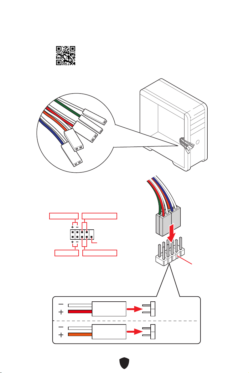
CPU_PWR1~2, ATX_PWR1: Power Connectors................................................... 35
JCI1: Chassis Intrusion Connector....................................................................... 36
JCOM1 : Serial Port connector............................................................................. 36
JUSB5: USB 3.2 Gen 1 Type-C Front Panel Connector ....................................... 37
JUSB3~4: USB 3.2 Gen 1 Connectors .................................................................. 37
JUSB1~2: USB 2.0 Connectors............................................................................. 38
JTPM1: TPM Module Connector........................................................................... 38
CPU_FAN1, PUMP_FAN1, SYS_FAN1~2: Fan Connectors.................................. 39
JBAT1: Clear CMOS (Reset BIOS) Jumper........................................................... 40
............................................................................................ 40
JRGB1: RGB LED connector................................................................................. 41
JARGB_V2_1~2: A-RAINBOW V2 (ARGB Gen2) LED connectors......................... 42
EZ Debug LED....................................................................................................... 43
English

3
Installing OS, Drivers & MSI Center.......................................................................... 44
UEFI BIOS.................................................................................................................... 48
BIOS Setup............................................................................................................ 49
Resetting BIOS...................................................................................................... 50
Updating BIOS....................................................................................................... 50
Block Diagram............................................................................................................ 52

4
Quick Start
Thank you for purchasing a new motherboard from MSI®. This Quick Start section
provides demonstration diagrams about how to install your computer. Some of the
installations also provide video demonstrations. Please link to the URL to watch it
with the web browser on your phone or tablet. You may have even link to the URL by
scanning the QR code.
Preparing Tools and Components
Intel® LGA1700 CPU
LGA1700 CPU Fan
Graphics Card
SATA Hard Disk Drive
Phillips Screwdriver
Chassis
Power Supply Unit
A Package of Screws
Thermal Paste
DDR5 Memory

5
Safety Information
∙The components included in this package are prone to damage from electrostatic
discharge (ESD). Please adhere to the following instructions to ensure successful
computer assembly.
∙Ensure that all components are securely connected. Loose connections may cause
the computer to not recognize a component or fail to start.
∙Hold the motherboard by the edges to avoid touching sensitive components.
∙It is recommended to wear an electrostatic discharge (ESD) wrist strap when
handling the motherboard to prevent electrostatic damage. If an ESD wrist strap
is not available, discharge yourself of static electricity by touching another metal
object before handling the motherboard.
∙Store the motherboard in an electrostatic shielding container or on an anti-static
pad whenever the motherboard is not installed.
∙Before turning on the computer, ensure that there are no loose screws or metal
components on the motherboard or anywhere within the computer case.
∙Do not boot the computer before installation is completed. This could cause
permanent damage to the components as well as injury to the user.
∙If you need help during any installation step, please consult a certified computer
technician.
∙Always turn off the power supply and unplug the power cord from the power outlet
before installing or removing any computer component.
∙Keep this user guide for future reference.
∙Keep this motherboard away from humidity.
∙Make sure that your electrical outlet provides the same voltage as is indicated on
the PSU, before connecting the PSU to the electrical outlet.
∙Place the power cord such a way that people can not step on it. Do not place
anything over the power cord.
∙All cautions and warnings on the motherboard should be noted.
∙If any of the following situations arises, get the motherboard checked by service
personnel:
• Liquid has penetrated into the computer.
• The motherboard has been exposed to moisture.
• The motherboard does not work well or you can not get it work according to user
guide.
• The motherboard has been dropped and damaged.
• The motherboard has obvious sign of breakage.
∙Do not leave this motherboard in an environment above 60°C (140°F), it may damage
the motherboard.

6
Case stand-off notification
To prevent damage to the motherboard, any unnecessary mounting stand-off between
the motherboard circuits and the computer case is prohibited. The Case standoff keep
out zone signs will be marked on the backside of motherboard (as shown below) to
serve as a warning to user.
Avoid collision notification
Protective paint is printed around each screw hole to prevent parts from being
scratched.

7
Installing a Processor
⚽
∙https://youtu.be/KMf9oIDsGes
11
22
33
66
44
5577
88
99

8
Installing DDR5 memory
DIMMA2 DIMMA2
DIMMB2
DIMMA1
DIMMA2
DIMMB1
DIMMB2
∙https://youtu.be/XiNmkDNZcZk
⚽

9
HDD LED
RESET SW
Connecting the Front Panel Header
∙http://youtu.be/DPELIdVNZUI
JFP1
HDD LED HDD LED -
HDD LED +
POWER LED -
POWER LED +
POWER LED
RESET SW
POWER SW
POWER LED+
POWER LED-
HDD LED
⚽
1
2 10
9
Power LED
Reserved
Power Switch
JFP1
Reset SwitchHDD LED

10
Installing the Motherboard
22
∙https://youtu.be/wWI6Qt51Wnc
⚽
Torque:
3 kgf·cm*
*3 kgf·cm
= 0.3 N·m
= 2.6 lbf·in
33
11

11
Connecting the Power Connectors
∙http://youtu.be/gkDYyR_83I4
ATX_PWR1
⚽
CPU_PWR1
CPU_PWR2

12
44
55
Installing SATA Drives
∙http://youtu.be/RZsMpqxythc
11
22
33
⚽

13
Installing a Graphics Card
∙http://youtu.be/mG0GZpr9w_A
⚽
11
22
33
44
55
66

14
Connecting Peripheral Devices

15
Power On
44
33
1122

16
Specifications
CPU
∙Support Intel® Core™ 14th/ 13th/ 12th Gen Processors,
Intel® Pentium® Gold and Celeron® Processors*
∙Processor socket LGA1700
* Please go to www.msi.com to get the newest support status as new processors
are released.
Chipset Intel® B760 Chipset
Memory
∙4x DDR5 memory slots, supporting up to 192GB*
∙Supports 1R 5600 MHz (by JEDEC & POR)
∙Max. overclocking frequency:
• 1DPC 1R Max speed up to 6800+ MHz
• 1DPC 2R Max speed up to 6400+ MHz
• 2DPC 1R Max speed up to 6000+ MHz
• 2DPC 2R Max speed up to 5600+ MHz
∙Supports Intel® XMP 3.0 OC
∙Supports Dual-Controller Dual-Channel mode
∙Supports non-ECC, un-buffered memory
* Please refer to www.msi.com for more information on compatible memory.
Expansion Slots
∙2x PCIe x16 slots
• PCI_E1 slot (From CPU)
• Supports up to PCIe 4.0 x16
• PCI_E3 slot (From B760 chipset)
• Supports up to PCIe 4.0 x4
∙1x PCIe x1 slot (From B760 chipset)
• PCI_E2 supports up to PCIe 3.0 x1
Onboard Graphics
∙2x HDMI™ 2.1 ports with HDR, supports a maximum
resolution of 4K 60 Hz*/**
∙2x DisplayPort 1.4 ports with HBR2, supports a maximum
resolution of 4K 60Hz */**
* Available only on processors featuring integrated graphics.
** Graphics specifications may vary depending on the CPU installed.
SATA Ports ∙4x SATA 6Gb/s ports (From B760 chipset)*
* SATA_8 will be unavailable when installing M.2 SATA SSD in the M2_2 slot.
Continued on next column

17
Continued from previous column
M.2 SSD Slots
∙2x M.2 slots (Key M)
• M2_1 slot (From CPU)
• Supports up to PCIe 4.0 x4
• Supports 2242/ 2260/ 2280 storage devices
• M2_2 slot (From B760 chipset)
• Supports up to PCIe 4.0 x4
• Supports SATA 6Gb/s
• Supports 2242/ 2260/ 2280 storage devices
RAID ∙Supports RAID 0, RAID 1, RAID 5 and RAID 10 for SATA
storage devices
Audio Realtek® ALC897 Codec
∙7.1-Channel High Definition Audio
LAN ∙1x Realtek® 8125BG 2.5Gbps LAN controller
Wi-Fi & Bluetooth®
Intel® Wi-Fi 6E
∙The Wireless module is pre-installed in the M.2 (Key-E)
slot
∙Supports MU-MIMO TX/RX, 2.4GHz/ 5GHz/ 6GHz*
(160MHz) up to 2.4Gbps
∙Supports 802.11 a/ b/ g/ n/ ac/ ax
∙Supports Bluetooth® 5.3**, FIPS, FISMA
* The usage of Wi-Fi 6GHz band relies on Windows 11 support and depends on
every country’s regulations.
** The Bluetooth version may be updated, please refer to the Wi-Fi chipset
vendor’s website for details.
Power Connectors
∙1x 24-pin ATX main power connector
∙1x 8-pin +12V power connector
∙1x 4-pin ATX 12V power connector
Internal USB
Connectors
∙1x USB 3.2 Gen 1 5Gbps Type-C front panel port (From
B760 chipset)
∙2x USB 3.2 Gen 1 5Gbps connectors (From Hub-GL3523)
• Supports additional 4 USB 3.2 Gen 1 5Gbps ports
∙2x USB 2.0 connectors (From Hub-GL805G)
• Supports additional 4 USB 2.0 ports
Continued on next column

18
Continued from previous column
Fan Connectors
∙1x 4-pin CPU fan connector
∙1x 4-pin water-pump fan connector
∙2x 4-pin system fan connectors
System Connectors
∙1x Front panel audio connector
∙2x System panel connectors
∙1x Chassis Intrusion connector
∙1x TPM module connector
∙1x Serial port connector
Jumpers ∙1x Clear CMOS jumper
LED Features
∙4x EZ Debug LED
∙1x 4-pin RGB LED connector
∙2x 3-pin A-RAINBOW V2 (ARGB Gen2) LED connectors
Back Panel
Connectors
∙1x PS/2 keyboard /Mouse combo port
∙2x USB 2.0 Type-A ports (From B760 chipset)
∙2x DisplayPort
∙2x HDMI™ ports
∙2x USB 3.2 Gen 1 5Gbps Type-A ports (From B760 chipset)
∙1x 2.5G LAN (RJ45) jack
∙2x USB 3.2 Gen 2 10Gbps Type-A ports (From B760
chipset)
∙2x Wi-Fi Antenna connectors
∙3x Audio jacks
I/O Controller NUVOTON NCT6687D Controller Chip
Hardware Monitor
∙CPU/ System/ Chipset temperature detection
∙CPU/ System/ Pump fan speed detection
∙CPU/ System/ Pump fan speed control
Form Factor ∙Micro-ATX Form Factor
∙9.6 in. x 9.6 in. (244 mm x 244 mm)
Continued on next column

19
Continued from previous column
BIOS Features
∙1x 256 Mb flash
∙UEFI AMI BIOS
∙ACPI 6.4, SMBIOS 3.5
∙Multi-language
Software
∙Drivers
∙MSI Center
∙Intel Extreme Tuning Utility
∙CPU-Z MSI GAMING
∙Norton 360
∙AIDA64 Extreme - MSI Edition
∙Adobe Creative Cloud
∙Acrobat

20
Special Features
MSI Center
• Gaming Mode
• Smart Priority
• Game Highlights
• Mystic light
• Ambient Link
• Frozr AI Cooling
• LAN Manager
• User Scenario
• True Color
• Live Update
• Hardware Monitoring
• Super Charger
• Devices Speed Up
• Smart Image Finder
• MSI Companion
• System Diagnosis
Thermal Features
• Extended Heatsink Design
• K7 MOSFET thermal pad / Extra
choke pad
• Fan headers (CPU + PUMP +
SYSTEM)
Performance
• Core Boost
• VRM Power Design (VCPU / VGT /
AUX)
• Dual CPU Power
• Memory Boost
• Lightning Gen 4 PCI-E / M.2 Slot
• Front USB Type-C
• 2oz Copper thickened PCB
DIY Friendly
• PCI-E Steel Armor
• EZ M.2 Clip
• EZ DEBUG LED
• EZ LED Control
Audio
• Audio Boost
RGB
• Mystic Light Extension (RGB)
• Mystic Light Extension (A-RAINBOW
V2)
• Ambient Link
BIOS
• Click BIOS 5
Table of contents
Other MSI Motherboard manuals

MSI
MSI MS-6182 User manual

MSI
MSI MS-6380 User manual

MSI
MSI MS-7151 User manual

MSI
MSI P45 Platinum Series User manual

MSI
MSI Z68A-GD65 B3 series User manual

MSI
MSI 845 Ultra User manual

MSI
MSI MS-98F3 User manual

MSI
MSI Wind Board 330 User manual

MSI
MSI K9AGM2-F User manual

MSI
MSI H67MA-E45 series User manual

MSI
MSI G41M-P33 series User manual

MSI
MSI IM-GME965 User manual

MSI
MSI MS-7222 User manual

MSI
MSI Z87 MPOWER MAX User manual

MSI
MSI P67A-G43 (B3) User manual

MSI
MSI A88X-G45 GAMING User manual

MSI
MSI H110M PRO-VD User manual

MSI
MSI H6M-P30 (B3) User manual

MSI
MSI Z87I User manual

MSI
MSI K7N415 Pro User manual