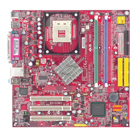
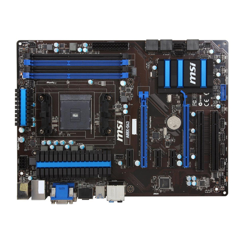
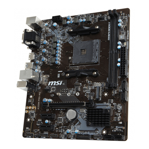
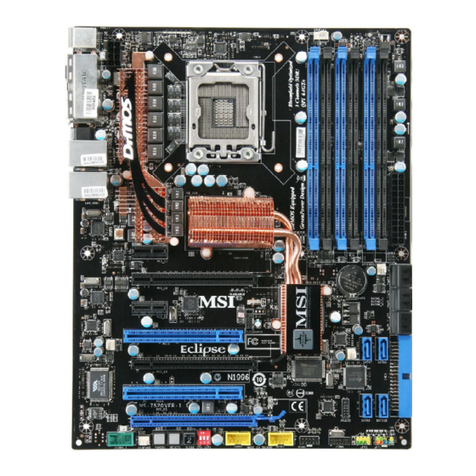
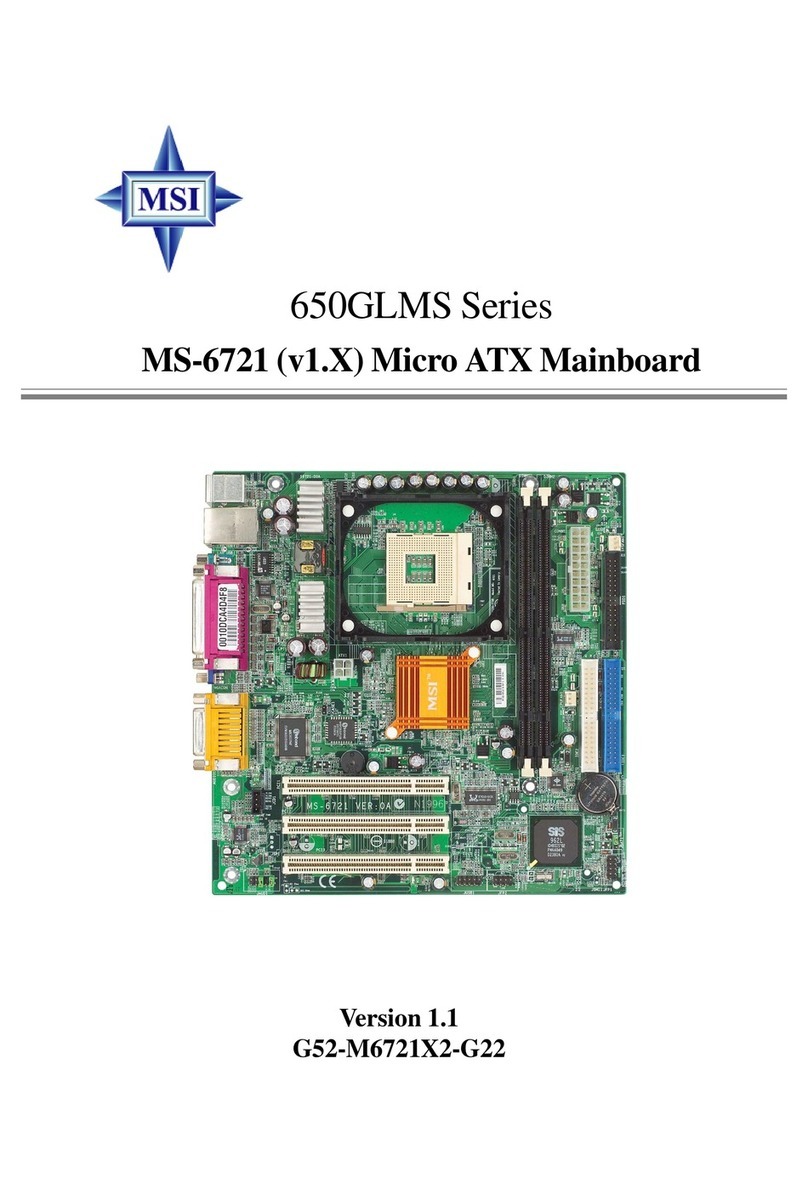
MSI MS-6382 User manual

Introduction
1-1
The MS6382 MICRO ATX mainboard is a high performance compu-
er mainboard based on KT266/VT8366 and VT8233 chipse . The KT266
chipse is ideal for high quali y and high in egra ion desk op and no ebook
AGP/PCI/LPC compu er sys ems based on Socke A processors.
The VT8366 Hos sys em con roller provides superior perfromance
be ween CPU, DRAM, AGP bus, and V-Link bus wi h pipelined, burs , and
concurren opera ion. The VT8233 V-Link Clien con roller is a highly
in egra ed PCI/LPC con roller. I suppor s five PCI slo s of arbi ra ion and
decoding for all in egra ed func ions and LPC bus.
For sophis ica ed power managemen , he Apollo KT266 chipse
provides independen clock s op con rol for he CPU/SDRAM, PCI, and
AGP buses and Dynamic CKE con rol for powering down of he SDRAM. A
sepera e suspend-well plane is implemen ed for he SDRAM con rol signals
for he Suspend- o-DRAM opera ion.
Chap er 1 con ains he following opics:
Mainboard Specifica ions 1-2
Mainboard Layou 1-4
Quick Componen s Guide 1-5
Key Fea ures 1-6
MSI Special Fea ures 1-6
Introduction

Chapter 1
1-2
CPU
!Socke A for AMD® DuronTM/A hlonTM processor.
!Suppor 600MHz up o 1.5GHz processor
Chipset
! VIA® VT8366 chipse . (552 BGA)
- FSB @200/266MHz
- AGP 4x and high bandwid h Vlink hos con roller
- Advanced memory con roller suppor PC200/266 DDR echnology
!VIA® VT8233 chipse . (376 BGA)
- High bandwid h Vlink clien con roller
- In egra ed fas er E herne con roller
- Direc sound ready AC97 digi al audio con roller
- Ul ra DMA 33/66/100 mas er mode EIDE con roller
- Suppor bo h ACPI and legacy APM power managemen
Clock Generator
!100MHz/133MHz clocks are suppor ed.
Main Memory
!Suppor four memory banks using wo 184-pin DDR DIMM
!Suppor a maximum memory size of 2GB
Slots
!One (Accelera ed Graphics Por ) AGP slo .
- AGP specifica ion complian
- Suppor AGP 2.0 1x/2x/4x
!One CNR (Communica ion Ne work Riser) slo .
!Three 32-bi Mas er PCI Bus slo s
!Suppor s 3.3v/5v PCI bus In erface.
n-Board IDE
!Dual Channel mas er mode IDE con roller on he VIA® VT8233 Chipse
provides IDE HDD/CD-ROM wi h PIO, Bus Mas er and Ul ra DMA 33/66/
100 opera ion modes.
!Can connec up o four IDE devices.
Mainboard Specifications

Introduction
1-3
Audio
!Chip In egra ed
- Direc Sound AC97 Audio
!CT5880 Hardware Audio (Op ion)
n-Board Peripherals
!On-Board Peripherals include:
- 1 floppy por suppor s 2 FDD wi h 360K, 720K, 1.2M, 1.44M and 2.
88Mby es.
- 2 serial por s (COMA + COM B)
- 1 parallel por suppor s SPP/EPP/ECP mode
- 6 USB por s (2 Rear Connec ors/ 2 USB Fron Pin Headers - 4 por s)
- 1 IrDA connec or for SIR/ASKIR/HPSIR.
- 1 Audio/Game por
BI S
!The mainboard BIOS provides Plug & Play BIOS which de ec s he
peripheral devices and expansion cards of he board au oma ically.
!The mainboard provides a Desk op Managemen In erface (DMI) func-
ion which records your mainboard specifica ions.
Dimension
!ATX Form Fac or: 24.3cm x 23.4cm
Mounting
!6 moun ing holes.

Chapter 1
1-4
Mainboard Layout
MS-6382 MICRO ATX Mainboard
SOCKET 462
Top : mous e
Bottom: ke
y
board
USB
Top : port 1
Bottom: port 2
CD_IN
MODEM_IN
AGP Slot
BATT
+
BIOS
86& !!
86&!$$
,,4
,,4
1,-
1,- .,,
PC I Slot
PC I Slot
PC I Slot
CNR JMDM1 JUSB2 JUSB1
SW1
J3
J2
J1
CPU FAN
ATX
Power Suppy
JFP1
SFAN1
J10JGL1
JBAT1
JGS1
To p :
Midi / Game port
Bottom:
Line- ut
Line-In
Mic
To p : L PT
Bottom:
C M A
C M B
JAU1
+6#&&
CD_IN
AUX_IN

Introduction
1-5
Component Function Reference
Socke 462 Ins alling CPU p. 2-2
DDR1~2 Ins alling memory module p. 2-4
ATX Power Supply Ins alling power supply p. 2-6
FDD1 Connec ing o floppy disk drive p. 2-11
J2 Inser ing hermis or p. 2-11
IDE1 & IDE2 Connec ing o HDD drive p. 2-12
JFP1 Connec ing o case p. 2-13
JMDM1 Connec ing o modem card p. 2-14
J1 Connec ing o chassis in rusion swi ch p. 2-14
CPUFAN Connec ing o processor fan p. 2-15
SYSFAN Connec ing o sys em fan p. 2-15
JUSB1 & 2 Connec ing o USB devices p. 2-17
JAU1 Connec ing o Fron Panel Audio p. 2-18
JGL1 Connec ing o powering saving LED p. 2-19
JGS1 Connec ing o power saving swi ch P. 2-20
J3 Connec ing o IR module p. 2-20
JBAT1 Se ing clear CMOS P. 2-21
SW1 Se ing CPU FSB P. 2-22
J10 Se ing Beep on Buzzer or Speaker p. 2-22
AGP Inser ing AGP graphics card p. 2-23
PCI Slo Inser ing expansion cards p. 2-23
CNR Inser ing CNR card p. 2-23
Quick Components Guide

Chapter 1
1-6
!Micro ATX Form Fac or wi h PC99 color connec or
!Suppor Accelera ed Graphic Por (AGP) Add-On Card
!Suppor AMD® PGA Socke A Duron/A hlon processors a 200/
266MHz Sys em Bus Frequencies
!Chip In egra ed Audio (CT5880 hardware op ion)
!PC Aler Sys em Hardware Moni or
!Suppor DMI (Desk op Managemen In erface) hrough BIOS
!LAN Wake Up Func ion
!Modem (In ernal/Ex ernal) Ring Wake Up Func ion
!Suppor PCI 2.2
!Suspend o RAM/Disk
Key Features
MSI Special Features
The MSI special fea ures are designed by MSI R&D which are only
available in MSI mainboards. The 6382 mainboard is equipped wi h PC Aler TM
III.

Introduction
1-7
Features:
!Ne work Managemen
- Moni oring & remo e con rol
!Basic Sys em U ili ies
- Scandisk & Defragmen o main ain your HDD
!3D Graphics Design
- Enables a more friendly user in erface
!Sof ware U ili ies
- Sof Cooler Op imized Cooling
- Doc or Y2K diagnoses Y2K problems
- BusRacing func ion adjus s F.S.B under Windows 95/98
- MoSpeed speeds up your modem ransmission
PC Alert III
The PC Aler TM III is a u ili y you can find in he CD-ROM. The u ili y
is jus like your PC doc or ha can de ec he following PC hardware s a us
during real ime opera ion:
* moni or CPU & sys em empera ure
* moni or fan speed
* moni or sys em vol age
* moni or chassis in rusion
If one of he i ems above is abnormal, he program main screen will be imme-
dia ely shown on he screen, wi h he abnormal i em highligh ed in red. This
will con inue o be shown un il user disables warning.

Hardware Setup
2-1
This chapter provides you with the information about hardware setup
procedures. While doing the installation, be careful in holding the compo-
nents and follow the installation procedures. For some components, if you
install in the wrong orientation, the components will not work properly.
Besides, please use a grounded wrist strap before handling computer
components. Static electricity may damage the components.
.
This chapter contains the following topics
Central Processing Unit (CPU) 2-2
Memory Installation 2-4
Power Supply 2-6
Back Panel 2-7
Connectors 2-11
Jumpers 2-21
Slots 2-24
Hardware Setup

Chapter 2
2-2
Central Processing Unit: CPU
The mainboard supports AMD® DuronTM / Athlon processors. The
mainboard uses a CPU socket called Socket A for easy CPU installation.
Make sure that the CPU has a Heat Sink and a cooling fan attached to
prevent overheating. If you do not find the Heat Sink and cooling fan,
contact your dealer or purchase them before turning on the computer.
Overheating will seriously damage the CPU and
system. After inserting the Heat Sink and cooling fan
, check if the cooling fan can work properly to protect
the CPU.
!
WARNING!
1. Pull the lever sideways away
from the socket. Then, raise the
lever up to a 90-degree
angle.
2. Look for the cut edge. The
cut edge should point
towards the lever pivot. The
CPU will only fit in the
correct orientation.
3. Hold the CPU down firmly,
and then close the lever to
complete the installation.
CPU Installation Procedures Open Lever
Cut edge
Sliding
Plate
Close
Lever

Hardware Setup
2-3
OVERCLOCKING
he motherboard are designed to support overclocking.
Make sure your components are able to tolerate such
abnormal setting while doing overclocking. Any attempt to
operate beyond product specifications is not recommended.
We do not guarantee the damages or risks caused by
inadequate operation or beyond product specification.
!
WARNING!
CPU Core Speed Derivation Procedure
The mainboard can not automatically set the CPU Host Bus Frequency
Clock. Please refer to 2-22 SW1 for the manual setting.
If CPU Clock = 100MHz (set by SW1)
Core/Bus ratio = 7
then CPU core speed = Host Clock x Core/Bus ratio
= 100MHz x 7
= 700MHz

Chapter 2
2-4
Memory Installation
The mainboard provides 2 sockets for 184-pin single or double side
DDR memory modules. To operate properly, at least one DDR module must be
installed. The mainboard supports the memory size from 32MB to 2 GB.
SOCKET 462
DDR1
DDR2
You can install memory modules in any combination as follows
Socket Memory Module Total Memory
Socket 1 (Bank 0 & Bank 1) 32MB, 64MB, 128MB, 256MB, 512MB 32MB~512MB
Socket 2 (Bank 2 & Bank 3) 32MB, 64MB, 128MB, 256MB, 512MB 32MB~512MB
Total System Memory 32MB~2GB

Hardware Setup
2-5
Installing DDR Module
1. The DDR slot has 2 Notch Keys VOLT and DRAM, so the DDR
memory module can only fit in one direction.
2. Insert the DDR memory module vertically into the DDR slot. Then
push it in.
3. The plastic clip at the side of the DDR slot will automatically close.
Single Sided DDR Module
Double Sided DDR Module
VOLT

Chapter 2
2-6
Power Supply
ATX 20-Pin Power Supply
This connector allows you to connect to an ATX power supply. To
connect to the ATX power supply, make sure the plugs of the power supply
insert in the proper orientation and the pins are aligned. Then push down the
power supply firmly into the connector.
The mainboard supports ATX power supply for the power system. As
the mainboard has the instant power on function, make sure that all compo-
nents are installed properly before inserting the power supply connector to
ensure that no damage will be done.
SOCKET 462
ATX
Power Connector
10 1
11
20

Hardware Setup
2-7
The Back Panel provides the following connectors
Midi/JoystickMouse
eyboard USB
Parallel
COM A COM B MIC
L-out L-in
Mouse Connector
The mainboard provides a standard PS/2® mouse mini DIN connector
for attaching a PS/2® mouse. You can plug a PS/2® mouse directly into this
connector.
PS/2 Mouse (6-pin Female)
21
3
4
5
6
PIN SIGNAL DESCRIPTION
1 Mouse DATA Mouse DATA
2 NC No connection
3 GND Ground
4 VCC +5V
5 Mouse Clock Mouse clock
6 NC No connection
Pin Definition
Back Panel

Chapter 2
2-8
Key oard Connector
The mainboard provides a standard PS/2® keyboard mini DIN connec-
tor for attaching a PS/2® keyboard. You can plug a PS/2® keyboard directly into
this connector.
21
34
5
6
PS/2 eyboard (6-pin Female) PIN SIGNAL DESCRIPTION
1 Keybo rd DATA Keybo rd DATA
2 NC No connection
3 GND Ground
4 VCC +5V
5 Keybo rd Clock Keybo rd clock
6 NC No connection
Pin Definition
USB Connectors
The mainboard provides a UHCI (Universal Host Controller Interface)
Universal Serial Bus root for attaching USB devices such as keyboard, mouse
or other USB devices. You can plug the USB device directly into this connector.
USB Ports
1 2 3 4
5 6 7 8
PIN SIGNAL DESCRIPTION
1 VCC +5V
2 -D t 0 Neg tive D t Ch nnel 0
3 +D t 0 Positive D t Ch nnel 0
4 GND Ground
5 VCC +5V
6 -D t 1 Positive D t Ch nnel 1
7 +D t 1 Neg tive D t Ch nnel 1
8 GND Ground
USB Port Description

Hardware Setup
2-9
Parallel Port Connector
The mainboard provides a 25 pin female centronic connector for LPT.
A parallel port is a standard printer port that also supports Enhanced Parallel
Port (EPP) and Extended Capabilities Parallel Port (ECP).
13 1
14
25
PIN SIGNAL DESCRIPTION
1 STROBE Strobe
2DATA0 Dt0
3DATA1 Dt1
4DATA2 Dt2
5DATA3 Dt3
6DATA4 Dt4
7DATA5 Dt5
8DATA6 Dt6
9DATA7 Dt7
10 ACK# Acknowledge
11 BUSY Busy
12 PE P per End
13 SELECT Select
14 AUTO FEED# Autom tic Feed
15 ERR# Error
16 INIT# Initi lize Printer
17 SLIN# Select In
18 GND Ground
19 GND Ground
20 GND Ground
21 GND Ground
22 GND Ground
23 GND Ground
24 GND Ground
25 GND Ground1
Pin Definition

Chapter 2
2-10
Joystick/Midi Connectors
You can connect game joysticks or game pads to this 15-pin female
connector for playing game. You can also connect MIDI devices for playing or
editing professional audio.
Audio Port Connectors
Line Out is a connector for headphone or speakers. Line In is used for
external CD player, tape players or other audio devices to be recorded by your
computer or played through the Line Out. Mic is a connector for the
microphone.
L-out L-in MIC
Serial Port Connectors: COM A & COM B
The mainboard has two 9-pin male DIN connectors for serial port COM
A and COM B. You can attach a mouse or other serial devices directly into this
connector.
1 2 3 4 5
6 7 8 9
PIN SIGNAL DESCRIPTION
1 DCD Data Carry Detect
2 SIN Serial In or Receive Data
3 SOUT Serial Out or Transmit Data
4 DTR Data Terminal Ready)
5 ND round
6 DSR Data Set Ready
7 RTS Request To Send
8 CTS Clear To Send
9 RI Ring Indicate
9-Pin Male DIN Connectors Pin Definition

Hardware Setup
2-11
Floppy Disk Drive Connector: FDD1
The mainboard provides a standard floppy disk drive connector that
supports 360K, 720K, 1.2M, 1.44M and 2.88M floppy disk types.
Connectors
Top Tech III: J2
The mainboard provides a 2-pin connector which can be inserted with a 20cm
length thermistor. The BIOS setup for Top Tech III should be set to En-
able if you want to use the thermistor to detect the components temperature.
SOCKET 462
20CM length
Thermistor
FDD1
33
1
SOCKET 462
34
2

Chapter 2
2-12
Hard Disk Connectors: IDE1 & IDE2
The mainboard has an IDE controller on the VT8233 chipset that pro-
vides IDE HDD/CD-ROM with PIO, Bus Master and Ultra DMA66/100 opera-
tions modes. It has two HDD connectors IDE1 (Primary) and IDE2 (Secondary).
You can connect up to four hard disk drives, CD-ROM or 120MB Floppy to
IDE1 and IDE2.
IDE1 (Primary IDE Connector)
- The first hard disk drive should always be connected to IDE1. You can
connect a Master and a Slave drive to IDE1.
IDE2 (Secondary IDE Connector)
- You can connect a Master and a Slave drive to IDE2.
!TIP:
If you install two hard disks, you must configure the second drive to
Slave mode by setting its jumper accordingly. Refer to the hard disk
documentation for the jumper setting.
IDE1 IDE2
12
39 40
12
39 40
SOCKET 462

Hardware Setup
2-13
Case Connector: JFP1
The case connector block JFP1 allows you to connect the Power Switch,
Reset Switch, Power LED, Speaker, Key Lock and HDD LED.
JFP1
Single
Color LED
SOCKET 462
Power
Switch
Power
LED
+
Reset
Switch
HDD
LED
+
Speaker
Buzzer
(short pin)
14
15
Keylock
Dual
Color LED
Power Switch
Connect to a 2-pin push button switch.
Reset Switch
Reset switch is used to reboot the system rather than turning the power ON/OFF. A oid rebooting while
the HDD LED is lit. You can connect the Reset switch from the system case to this pin.
Power LED
The Power LED is lit while the system power is on. You can connect the Power LED from the system case
to this pin. There are two types of LED that you can use: 3-pin single color LED or 2-pin dual color LED
(ACPI request).
a. 3 pin single color LED connector to pin 4,5 & 6. This LED will lit when the system is on.
b. 2 pin dual color LED connector to pin 5 & 6.
GREEN color: Indicate the system is in full-on mode.
ORANGE color: Indicate the system is in suspend mode.
Speaker
Speaker from the system case is connected to this pin.
If on-board Buzzer is a ailable:
Short pin 14-15: On-board Buzzer Enabled.
Open pin 14-15: On-board Buzzer Disabled.
HDD LED
HDD LED shows the acti ity of a hard disk dri e. A oid turning the power off while the HDD led is lit. You
can connect the HDD LED from the system case to this pin.
Other manuals for MS-6382
2
Table of contents
Other MSI Motherboard manuals

MSI
MSI 7C56-002R User manual

MSI
MSI LPX SI15 User manual

MSI
MSI E7505 Master-LS2 User manual

MSI
MSI MEG Z590 ACE User manual

MSI
MSI MS-7596 (v1.x) User manual

MSI
MSI H67MA-ED55 series User manual

MSI
MSI H6M-P20 (G3) User manual

MSI
MSI H110M-A PRO M2 User manual

MSI
MSI MS-7646M1 User manual

MSI
MSI MEG Z390 ACE User manual
MSI
MSI MAG B660 TOMAHAWK WIFI User manual

MSI
MSI H410M PRO-C User manual

MSI
MSI KT3 Ultra2-C MS-6593 User manual

MSI
MSI 925XE Neo Platinum User manual

MSI
MSI PRO B660M-A WIFI DDR4 User manual

MSI
MSI MPG Z390 GAMING EDGE AC User manual

MSI
MSI MS-7104 User manual

MSI
MSI K7N2GM2-ILSR User manual

MSI
MSI MS-7151 User manual

MSI
MSI P35 Platinum Combo series User manual