MSI MS-7082 User manual

i
G52-M7082X3
661FM3 Series
MS-7082 (v1.X) Micro ATX Mainboard

ii
Manual Rev: 1.1
Release Date: September 2004
FCC-B Radio Frequency Interference Statement
This equipment has been tested and found to comply with the limits for a class
B digital device, pursuant to part 15 of the FCC rules. These limits are designed
to provide reasonable protection against harmful interference when the equip-
ment is operated in a commercial environment. This equipment generates, uses
and can radiate radio frequency energy and, if not installed and used in accor-
dance with the instruction manual, may cause harmful interference to radio
communications. Operation of this equipment in a residential area is likely to
cause harmful interference, in which case the user will be required to correct
the interference at his own expense.
Notice 1
The changes or modifications not expressly approved by the party respon-
sible for compliance could void the user’s authority to operate the equipment.
Notice 2
Shielded interface cables and A.C. power cord, if any, must be used in order to
comply with the emission limits.
VOIR LA NOTICE D’INSTALLATION AVANT DE RACCORDER AU
RESEAU.
Micro-Star International
MS-7082

iii
Copyright Notice
The material in this document is the intellectual property of MICRO-STAR
INTERNATIONAL. We take every care in the preparation of this document,
but no guarantee is given as to the correctness of its contents. Our products
are under continual improvement and we reserve the right to make changes
without notice.
Trademarks
All trademarks are the properties of their respective owners.
AMD, Athlon™, Athlon™ XP, Thoroughbred™, and Duron™ are registered
trademarks of AMD Corporation.
Intel®and Pentium®are registered trademarks of Intel Corporation.
PS/2 and OS®/2 are registered trademarks of International Business Machines
Corporation.
Microsoft is a registered trademark of Microsoft Corporation. Windows®98/
2000/NT/XP are registered trademarks of Microsoft Corporation.
NVIDIA, the NVIDIA logo, DualNet, and nForce are registered trademarks or
trademarks of NVIDIA Corporation in the United States and/or other countries.
Netware®is a registered trademark of Novell, Inc.
Award®is a registered trademark of Phoenix Technologies Ltd.
AMI®is a registered trademark of American Megatrends Inc.
Kensington and MicroSaver are registered trademarks of the Kensington Tech-
nology Group.
PCMCIA and CardBus are registered trademarks of the Personal Computer
Memory Card International Association.
Revision History
Revision Revision History Date
V1.0 First release for PCB 1.x with August 2004
chipsets SiS661FX / 648FX
& SiS964 / 964L
V1.1 Manual cover updates September 2004

iv
1. Always read the safety instructions carefully.
2. Keep this User’s Manual for future reference.
3. Keep this equipment away from humidity.
4. Lay this equipment on a reliable flat surface before setting it up.
5. The openings on the enclosure are for air convection hence protects the
equipment from overheating. Do not cover the openings.
6. Make sure the voltage of the power source and adjust properly 110/220V
before connecting the equipment to the power inlet.
7. Place the power cord such a way that people can not step on it. Do not
place anything over the power cord.
8. Always Unplug the Power Cord before inserting any add-on card or module.
9. All cautions and warnings on the equipment should be noted.
10. Never pour any liquid into the opening that could damage or cause electrical
shock.
11. If any of the following situations arises, get the equipment checked by a
service personnel:
hThe power cord or plug is damaged.
hLiquid has penetrated into the equipment.
hThe equipment has been exposed to moisture.
hThe equipment has not work well or you can not get it work according
to User’s Manual.
hThe equipment has dropped and damaged.
hThe equipment has obvious sign of breakage.
12. Do not leave this equipment in an environment unconditioned, storage
temperature above 600 C (1400F), it may damage the equipment.
Safety Instructions
CAUTION: Danger of explosion if battery is incorrectly replaced.
Replace only with the same or equivalent type recommended by the
manufacturer.

v
CONTENTS
FCC-B Radio Frequency Interference Statement ........................................... ii
Copyright Notice .......................................................................................... iii
Revision History ........................................................................................... iii
Safety Instructions ....................................................................................... iv
Chapter 1. Getting Started ........................................................................ 1-1
Mainboard Specifications .................................................................... 1-2
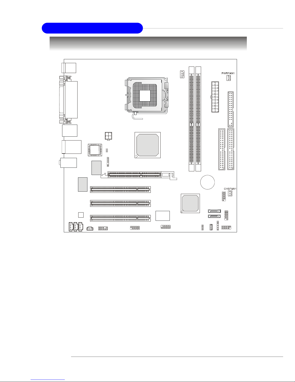
Mainboard Layout ............................................................................... 1-4
Chapter 2. Hardware Setup ....................................................................... 2-1
Quick Components Guide .................................................................... 2-2
Central Processing Unit: CPU .............................................................. 2-3
Memory ................................................................................................ 2-7
Introduction to DDR SDRAM ....................................................... 2-7
DDR Module Combination ............................................................ 2-8
Installing DDR Modules ............................................................... 2-8
Power Supply ....................................................................................... 2-9
ATX 20-Pin Power Connector: CONN1 ......................................... 2-9
ATX 12V Power Connector: JPW2000 ........................................... 2-9
Back Panel .......................................................................................... 2-10
Mouse Connector ....................................................................... 2-10
Keyboard Connector ................................................................... 2-11
USB Connectors .......................................................................... 2-11
Serial Port Connector ................................................................... 2-12
VGA Connector ........................................................................... 2-12
IEEE 1394 Port (Optional) ............................................................ 2-12
RJ-45 LAN Jack ........................................................................... 2-13
Audio Port Connectors ............................................................... 2-14
Parallel Port Connector: LPT1 ...................................................... 2-15
Connectors ............................................................................................... 2-15
Floppy Disk Drive Connector: FDD1 ........................................... 2-16

vi
Fan Power Connectors: CPUFAN2 & POWFAN1& CHSFAN1 ... 2-16
Hard Disk Connectors: IDE1 & IDE2 ........................................... 2-17
Serial ATA HDD Connectors: SATA1 & SATA2 ......................... 2-18
IEEE 1394 Connector: J1394_1 (Optional) .................................... 2-19
Serial Port Connector: JCOM1 ..................................................... 2-19
Front Panel Connectors: JFP1 ..................................................... 2-20
Aux Line-In Connector: AUX_IN1 .............................................. 2-20
CD-In Connector: CD_IN1 .......................................................... 2-21
Front Panel Audio Connector: JAUD1 ........................................ 2-21
Front USB Connectors: JUSB1 & JUSB2 ..................................... 2-22
SPDIF Connector: JSP1 ............................................................... 2-22
IrDA Infrared Modele Header: IR1 .............................................. 2-23
Wake On LAN Connector: JWOL ............................................... 2-23
Wake Up On Modem Connector: JMR1 ...................................... 2-23
Jumpers .............................................................................................. 2-22
Clear CMOS Jumper: JBAT1 ........................................................ 2-24
BIOS Flash Jumper: BIOS_WP1 .................................................. 2-24
Slots ................................................................................................... 2-25
AGP (Accelerated Graphics Port) Slot ......................................... 2-25
PCI (Peripheral Component Interconnect) Slots .......................... 2-25
PCI Interrupt Request Routing .................................................... 2-25

1-1
Hardware Setup
Chapter 1. Getting
Started
Thank you for purchasing 661FM3 Series (MS-7082 v1.X) Micro ATX
mainboard. The 661FM3 Series (MS-7082 v1.X) is based on SiS®
661FX / 648FX & SiS®964 / 964L chipsets for optimal system
efficiency. Designed to fit the advanced Intel®Pentium 4/Celeron
DTM (LGA775) processor, the 661FM3 Series (MS-7082 v1.X) delivers
a high performance and professional desktop platform solution.
Getting Started

1-2
MS-7082 Micro ATX Mainboard
Mainboard Specifications
CPU
hSupports Intel®Pentium 4 / Celeron-D in the 775-land package
hSupports 533MHz, 800MHz FSB
hSupports 2004 Performance FMB CPU VR Design
hSupports 3/4 pin CPU Fan Pin-Header with Fan Speed Control
(For the latest information about CPU, please visit http://www.msi.com.tw/program/
products/mainboard/mbd/pro_mbd_cpu_support.php )
Chipset
hSiS®661FX / 648FX Chipset
- Integrated graphic controller (661FX only)
- Support DDR333/400 SDRAM
hSiS®964 / 964L Chipset
- High Definition Audio interface
- 8 USB 2.0/1.1 ports
- 2 channel Ultra ATA66/100/133 Bus Master IDE controller
- 2 serial ATA Host Controllers (964 only)
Main Memory
hSupports 64-bit wide DDR
hAvailable bandwidth up to 3.2GB/s (DDR 400)
hSupports 128Mb, 256Mb or 512Mb DDR technologies
(For the updated supporting memory modules, please visit http://www.msi.com.tw/
program/products/mainboard/mbd/pro_mbd_trp_list.php )
Slots
hOne AGP Slot
hThree PCI Slots (32-bit v2.3 Master PCI bus, supports 3.3/5v PCI bus interface)
On-Board IDE
hAn IDE controller on the 964/964L chipset provides IDE HDD/CD-ROM with PIO,
Bus Master and Ultra DMA66/100/133 operation modes.
hSupport 2 Serial ATA 150 ports.
On-Board Peripherals
hOn-Board Peripherals include:
- 1 floppy port supports 1 FDD with 360K, 720K, 1.2M, 1.44M and 2.88Mbytes.
- 2 serial port, Com1 on Rear IO, Com2 via pin header(IO bracket is optional)
- 1 parallel port supports SPP/EPP/ECP mode
- 8 USB 2.0/1.1 ports (Rear * 4 / Front * 4)
- 1 Line-In/Line-Out/Mic
- 1 RJ45 connector (Optional)
- 2 IEEE1394 connectors (Rear x1 and Front x 1)(Optional)
- 1 VGA port (661FX only)

1-3
Hardware Setup
Audio
hHigh Definition link controller integrated in 964/964L
h6 channels (HDA) audio codec
- Meet PC2001 audio performance requirement
- Can support SPDIF Out via bracket only
On-Board LAN (Optional)
hRealtekR 8100C / 8110S (optional)
- Integrated Fast Ethernet MAC and PHY in one chip.
- Supports 10Mb/s, 100Mb/s and 1000Mb/s (1000Mb/s for 8110S
only).
- Compliance with PCI 2.2.
- Supports ACPI Power Management
1394 (optional)
hSupports up to 2 * 1394 ports, one 6-pin 1394 connector on rear I/O, the other is
supported by onboard pinheader. Transfer rate is up
to 400Mbps.
hControlled by VIA 6307 chipset.
BIOS
h4MB Award BIOS
hProvides DMI 2.0, WFM 2.0, WOL, WOR and SMBus for system management.
Dimension
hMicro-ATX Form Factor: 24.4 cm (L) x 24.4 cm (W)
Mounting
h8 mounting holes

1-4
MS-7082 Micro ATX Mainboard
Mainboard Layout
MS-7082 v1.X Micro ATX Mainboard
CPUFAN2
JPW2000
SATA1
SATA2
CD_IN1
T:
M:
B:
Line-In
Line-Out
Mic Winbond
W83687THF
SiS
964/964L
SiS
661FX/648FX
BATT
+
DIMM1
DIMM2
PCI 3
PCI 2
PCI 1
IDE1
FDD1
IDE2
JFP1
JUSB2
JUSB1
JBAT1
JCOM1 J1394_1(Optional)
VIA
VT6307
JAUD1
JSP1
IR1
BIOS_WP1
Top : mouse
Bottom: keyboard
T:IEEE 1394 (Optional)
B:USB ports
CONN1
BIOS
T: LAN jack
B: USB ports
(Optional)
Top : Parallel Port
Bottom:
COM 1
VGA Port (661FX only)
RTL8100C/
8110S
Codec
AGPSlot
JWOL JMR1
AUX_IN1
MDM_IN1

2-1
Hardware Setup
Chapter 2. Hardware
Setup
This chapter tells you how to install the CPU, memory modules, and expansion
cards, as well as how to setup the jumpers on the mainboard. It also provides the
instructions on connecting the peripheral devices, such as the mouse, keyboard,
etc.
While doing the installation, be careful in holding the components and follow the
installation procedures.
Hardware Setup

2-2
MS-7082 Micro ATX Mainboard
Quick Components Guide
CPU, p.2-3
Back Panel
I/O, p.2-10
JUSB1, p.2-22
PCI Slots, p.2-25
JWOL, p.2-23
JPW2000, p.2-9
JAUD1, p.2-21
CONN1, p.2-9
CD_IN1, p.2-21
JCOM1, p.2-19
CPUFAN2, p.2-16
DDR DIMMs, p.2-7
JSP1, p.2-22
AGP Slot,
p.2-25
J1394_1,
p.2-19
(Optional)
JUSB2, p.2-22
JFP1, p.2-20
CFSFAN1, p.2-16
FDD1, p.2-16
PWRFAN1,
p.2-16
IDE1, IDE2,
p.2-17
SATA1/2, p.2-18
JMR1, p.2-23
JBAT1, p.2-24
AUX_IN1, p.2-20
MDM_IN1, p.2-20
BIOS_WP1, p.2-24
IR1, p.2-23

2-3
Hardware Setup
Central Processing Unit: CPU
The mainboard supports Intel®Pentium 4 / Celeron DTM (LGA775) processor. The
mainboard uses a CPU socket called LGA775. When you are installing the CPU, make
sure to install the heat sink/cooler to prevent overheating. If you do not have
the CPU, contact your dealer to purchase and install them before turning on the computer.
For the latest information about CPU, please visit http://www.msi.com.tw/pro-
gram/products/mainboard/mbd/pro_mbd_cpu_support.php.
MSI Reminds You...
Overheating
Overheating will seriously damage the CPU and system, always make
sure the cooling fan can work properly to protect the CPU from
overheating.
Replacing the CPU
While replacing the CPU, always turn off the ATX power supply or
unplug the power supply’s power cord from grounded outlet first to
ensure the safety of CPU.
The surface of LGA 775 CPU.
Remember to apply some silicone
heat transfer compound on it for
better heat dispersion.
Introduction of LGA 775 CPU
Yellow triangle is the Pin 1 indicator
The pin-pad side of LGA 775
CPU.
Yellow triangle is the Pin 1 indicator

2-4
MS-7082 Micro ATX Mainboard
2. Remove the cap from lever hinge
side (as the arrow shows).
1. The CPU has a plastic cap on it to
protect the contact from damage. Al-
ways cover it to protect the socket
pin until you are going to install the
CPU.
CPU, Heatsink & Fan Installation
When you are installing the CPU, make sure the CPU has a heat sink/
cooler fan attached on the top to prevent overheating. If you do not have the
heat sink/cooler fan, contact your dealer to purchase and install them before turning on
the computer. Meanwhile, do not forget to apply some silicon heat transfer compound
on CPU before installing the heat sink/cooler fan for better heatsinking.
Follow the steps below to install the CPU & cooling fan correctly. Wrong instal-
lation will cause the damage of your CPU & mainboard.
4. Open the load lever.3. The pins of socket reveal.

2-5
Hardware Setup
6. After confirming the CPU direction
for correction mating, put down the
CPU in the socket housing frame.
Be sure to grape on the edge of the
substrate. Note that the alignment
keys are matched.
8. Rotate the load plate onto the
package.
7. Visually inspect if the CPU is seated
well into the socket. If not, take out
the CPU with purely vertical motion
and reload it again.
alignment
key
5. Lift the load lever up and open the
load plate.

2-6
MS-7082 Micro ATX Mainboard
10. Align the holes on the mainboard
with the heatsink first. Pull down
the fan/heatsink until its four clips
get wedged in the holes of the
mainboard.
12.Turn over the mainboard to con-
firm that the clip-ends are cor-
rected inserted.
locking
switch
11. Press the four hooks down to fas-
ten the fan. Then rotate the locking
switch (refer to the correct direc-
tion marked on it) to lock the hooks
again.
9. Engage the load while pressing
down lightly onto the load plate, and
then secure the lever with the hook
under retention tab.
MSI Reminds You...
1. Confirm if your CPU heatsink/cooler is firmly installed before
turning on your system.
2. Check the information in PC Health Status of H/W Monitor in
BIOS (refer to p.3-20 for details) for the CPU temperature.
3. Make sure that the CPU socket pins are not turned up or pressed
down.

2-7
Hardware Setup
Memory
Themainboardprovidestwo184-pinunbufferedDDR266/DDR333/DDR400DDRSDRAM,
and supports the memory size up to 2GB without ECC. To operate properly, at least one
DIMM module must be installed.
(For the updated supporting memory modules, please visit http://www.msi.com.tw/
program/products/mainboard/mbd/pro_mbd_trp_list.php )
DDR DIMM Slots
(DDR 1~2)
Introduction to DDR SDRAM
DDR (Double Data Rate) SDRAM is similar to conventional SDRAM, but doubles the rate
by transferring data twice per cycle. It uses 2.5 volts as opposed to 3.3 volts used in
SDR SDRAM, and requires 184-pin DIMM modules rather than 168-pin DIMM modules
used by SDR SDRAM.

2-8
MS-7082 Micro ATX Mainboard
DDR Module Combination
Install at least one DIMM module on the slots. Memory modules can be installed on the
slots in any order. You can install either single- or double-sided modules to meet your
own needs.
Memory modules can be installed in any combination as follows:
Installing DDR Modules
1. The DDR DIMM has only one notch on the center of module. The module will only fit
in the right orientation.
2. Insert the DIMM memory module vertically into the DIMM slot. Then push it in until the
golden finger on the memory module is deeply inserted in the socket.
3. The plastic clip at each side of the DIMM slot will automatically close.
MSI Reminds You...
You can barely see the golden finger if the module is properly
inserted in the socket.
Volt Notch
S: Single Side D: Double Side
Slot Memory Module TotalMemory
DDR 2
(Bank 2 & 3) S/D 64MB~1GB
Maximum System Memory Supported 64MB~2GB
DDR 1
(Bank 0 & 1) S/D 64MB~1GB

2-9
Hardware Setup
Power Supply
The mainboard supports ATX power supply for the power system. Before inserting the
power supply connector, always make sure that all components are installed properly
to ensure that no damage will be caused.
ATX 20-Pin Power Connector: CONN1
This connector allows you to connect to an ATX power supply. To connect to the ATX
power supply, make sure the plug of the power supply is inserted in the proper
orientation and the pins are aligned. Then push down the power supply firmly into the
connector.
ATX 12V Power Connector: JPW2000
This 12V power connector is used to provide power to the CPU.
MSI Reminds You...
Power supply of 300-watt (and above) is highly recommended for
system stability.
PIN SIGNAL
11 3.3V
12 -12V
13 GND
14 PS_ON
15 GND
16 GND
17 GND
18 -5V
19 5V
20 5V
PIN SIGNAL
1 3.3V
2 3.3V
3 GND
45V
5 GND
65V
7 GND
8 PW_OK
9 5V_SB
10 12V
CONN1 Pin Definition
CONN1
10
1
20
11
JPW2000 1
3
4
2PIN SIGNAL
1 GND
2 GND
3 12V
4 12V
JPW1 Pin Definition

2-10
MS-7082 Micro ATX Mainboard
The back panel provides the following connectors:
Back Panel
Mouse Connector
The mainboard provides a standard PS/2®mouse mini DIN connector for attaching a PS/
2®mouse. You can plug a PS/2®mouse directly into this connector. The connector
location and pin assignments are as follows:
PIN SIGNAL DESCRIPTION
1 MouseDATA MouseDATA
2 NC Noconnection
3 GND Ground
4 VCC +5V
5 MouseClock Mouseclock
6 NC Noconnection
Pin Definition
Mouse Parallel
USB Port
Keyboard MIC
LAN
(Optional)
VGA Port
(for 661FX only) USB Port
1394
(Optional)
COM Port
L-in
L-out
PS/2 Mouse (6-pin Female)
21
3
4
5
6
Table of contents
Other MSI Motherboard manuals

MSI
MSI PRO Z790-A WIFI User manual

MSI
MSI 3200 Master Series User manual

MSI
MSI Z270I GAMING PRO CARBON AC User manual

MSI
MSI B350M PRO-VD PLUS User manual

MSI
MSI Z87 MPOWER MAX User manual

MSI
MSI P45D3Neo3 Series User manual

MSI
MSI MS-6390 User manual

MSI
MSI Big Bang-Fuzion MS-7582 User manual

MSI
MSI MPG X570-A PRO User manual

MSI
MSI MS-7067 User manual

MSI
MSI MS-7226 (V1.X) User manual

MSI
MSI MAG B650 TOMAHAWK WIFI User manual

MSI
MSI MPG Z490M GAMING EDGE WIFI User manual

MSI
MSI KM2M Combo User manual

MSI
MSI MS-9105 User manual

MSI
MSI B450M-A PRO MAX User manual

MSI
MSI KT4M User manual

MSI
MSI Z97-G43 GAMING User manual

MSI
MSI MS-6526 User manual

MSI
MSI B360 GAMING PLUS User manual