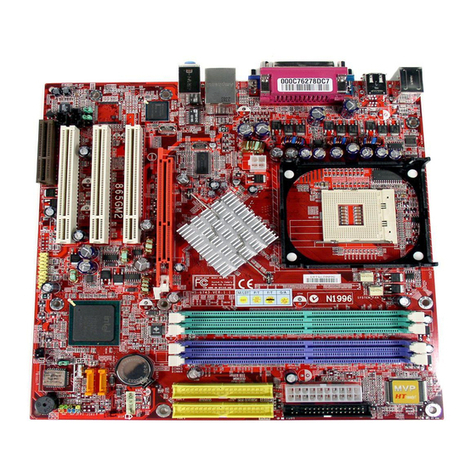
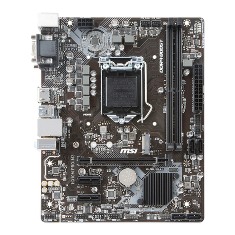
MSI 694T Pro User manual

v
Contents
Chapter 1. Introduction ...............................................................1-1
MainboardSpecification ............................................................1-2
MainboardLayout .....................................................................1-4
Quick Components Guide .........................................................1-5
Key Features ............................................................................1-6
MSI Special Features................................................................1-7
T.O.P Tech™ ......................................................................1-7
PC Alert™ III .......................................................................1-8
D-LED™ & D-Bracket™....................................................1-10
Fuzzy Logic™ III ...............................................................1-12
Chapter 2. Hardware Setup ........................................................2-1
Central Processing Unit: CPU ...................................................2-2
CPU Installation Procedures ...............................................2-2
CPUCoreSpeedDerivationProcedure................................2-3
Memory Installation...................................................................2-4
Module Installation Procedures ...........................................2-5
Power Supply............................................................................2-6
ATX 20-Pin Power Supply....................................................2-6
Back Panel ...............................................................................2-7
MouseConnector................................................................2-7
KeyboardConnector ...........................................................2-8
USB Connectors .................................................................2-8
Parallel Port Connector .......................................................2-9
Serial Port Connector: COM A & COM B ..........................2-10
Joystick/Midi Connectors ..................................................2-10
Audio Port Connectors ......................................................2-10
Connectors ............................................................................. 2-11
Floppy Disk Drive Connector: FDD1 .................................. 2-11
Hard Disk Connectors: IDE1 & IDE2 .................................2-12

vi
Case Connector: JFP1 ......................................................2-13
Power Switch....................................................................2-13
Reset Switch ....................................................................2-13
PowerLED........................................................................2-13
Speaker ............................................................................2-14
HDDLED ..........................................................................2-14
Wake On Ring Connector: JMDM1 ...................................2-15
Wake On LAN Connector: JWOL1 ....................................2-15
IrDAInfraredModuleConnector:J4 ...................................2-16
Modem-InConnector: MODEM_IN ....................................2-16
CD-InConnector:CD_IN ...................................................2-17
AuxLine-InConnector:AUX_IN .........................................2-17
Fan Power Connectors: CPUFAN/SYSFAN.......................2-18
USB PC To PC Connector: USB2 (Optional) .....................2-19
D-Bracket™ Connector: JDLED ........................................2-22
Jumpers ..................................................................................2-23
Clear CMOS Jumper: JBAT1 .............................................2-23
Slots .......................................................................................2-24
AGP (Accelerated Graphics Port) Slot ..............................2-24
AMR (Audio Modem Riser) Slot ........................................2-24
PCI Slots ..........................................................................2-24
ISA Slot ............................................................................2-25
PCI Interrupt Request Routing ...........................................2-25
Chapter 3. AMI® BIOS Setup......................................................3-1
Entering Setup ..........................................................................3-2
Control Keys .............................................................................3-2
Getting Help..............................................................................3-3
The Main Menu .........................................................................3-4
Standard CMOS Features .........................................................3-6
AdvancedBIOS Features ..........................................................3-8

vii
Advanced Chipset Features .................................................... 3-11
Power Management Setup ......................................................3-15
PNP/PCIConfigurations ..........................................................3-19
IntegratedPeripherals .............................................................3-21
HardwareMonitorSetup..........................................................3-25
Load Optimized/Fail-Safe Defaults ..........................................3-27
Supervisor/UserPassword ......................................................3-29
IDE HDD AUTO Detection .......................................................3-31
Save & Exit Setup...................................................................3-32
Exit Without Saving.................................................................3-33
Chapter 4. Award® BIOS Setup .................................................4-1
Entering Setup ..........................................................................4-2
Control Keys .............................................................................4-2
Getting Help..............................................................................4-3
The Main Menu .........................................................................4-4
Standard CMOS Setup .............................................................4-6
AdvancedBIOS Features ..........................................................4-8
Advanced Chipset Features ....................................................4-12
IntegratedPeripherals .............................................................4-15
Power Management Setup ......................................................4-19
PnP/PCI Configuration Setup ..................................................4-25
PC Health Status ....................................................................4-27
Frequency/Voltage Control.....................................................4-28
Load Fail-Safe/Optimized Defaults ..........................................4-29
Chapter 5. Installing Drivers .......................................................5-1
Overview....................................................................................5-2
System Requirements ........................................................5-2
Driver Installation for Windows® 98SE ......................................5-3
Driver Installation for Windows® 2000 .......................................5-5
Driver Installation for Windows® ME..........................................5-7
viii
Driver Installation for Windows® NT4.0 ......................................5-9
Appendix A: USB PC to PC Networking Function..................... A-1
Installing GeneLink™ LAN Driver.............................................. A-2
Using USB PC to PC Networking Function .............................. A-4
Glossary............................................................................................ I

Introduction
1-1
Chapter 1.
Introduction 1
The 694T Pro (MS-6309 v5.X) ATX mainboard is a high-performance
computer mainboard based on VIA®Apollo Pro133T chipset. The 694T Pro
(MS-6309 V5.X) is optimized to support the whole series of new generation
Intel®Pentium®III (FC-PGA/FC-PGA2) processor for high-end business/
personal desktop market.
The Apollo Pro133T chipset consists of the VT82C694T North
Bridge and the VT82C686B South Bridge. The VT82C694T is a Socket-370
system logic north bridge with the addition of 133 MHz capability for both
the CPU and SDRAM interfaces. It may be used to implement desktop
computer systems from 66MHz to 133MHz based on Socket-370. The
primary features of the VT82C694T are: Socket-370 CPU (Front Side Bus)
Interface (66 / 100 / 133MHz), DRAM Memory Interface (66 / 100 / 133MHz),
AGP Bus Interface (66MHz), PCI Bus Interface (33MHz).
TheVT82C686BPSIPC (PCI Super-I/O Integrated Peripheral
Controller) is a high integration, high performance, power-efficient, and high
compatibility device that supports Intel and non-Intel based processor to
PCI bus bridge functionality to make a complete Microsoft PC99-compliant
PCI/ISA system.
This chapter includes the following topics:
Mainboard Specification 1-2
Mainboard Layout 1-4
Quick Components Guide 1-5
Key Features 1-6
MSI Special Features 1-7

Chapter 1
1-2
CPU
zSupports Socket 370 for whole series of new generation of Intel®
Celeron™ / Pentium III (FC-PGA)/(FC-PGA2) and VIA®C3 processors
zSupports500MHz,550MHz,600MHz,633MHz,667MHz,700MHz,
733MHz,800MHz,866MHz,933MHz,1GHz,1.1GHz,1.13GHzandupto
1.2GHz
Chipset
zVIA®694T chipset (520 BGA)
-Supports66/100/133MHzFSB
- AGP 4x and PCI plus Advanced ECC Memory Controller
- Supports PC100/133 SDRAM, VCM & ESDRAM technology
zVIA®VT82C686Bchipset(352BGA)
- Enhanced Power Management Features
- Integrated Super I/O (FDC, LPT, COM 1/2, and IR)
- DirectSound AC97 Audio
- Integrated hardware Soundblaster
- Dual bus Master IDE Ultra DMA33/66/100
-ACPI
Clock Generator
z66/100/133MHz clocks are supported.
Main Memory
zSupports six memory banks using three 168-pin unbuffered DIMM
zSupportsamaximummemorysizeof 1.5GB (32M x8)
zSupports 3.3v SDRAM DIMM
Slots
zOne AGP (Accelerated Graphics Port) slot
- AGP specification compliant
- SupportsAGP1x/2x/4x
zOne AMR (Audio Modem Riser) slot
zFive 32-bit Master PCI Bus slots and one 16-bit ISA bus slots
zSupports 3.3v/5v PCI bus Interface
Mainboard Specification

Introduction
1-3
On-Board IDE
zAn IDE controller on the VIA®VT82C686B chipset provides IDE HDD/
CD-ROM with PIO, Bus Master and Ultra DMA 33/66/100 operation
modes.
zCan connect up to four IDE devices
On-Board Peripherals
zOn-Board Peripherals include:
- 1 floppy port supports 2 FDDs with 360K, 720K, 1.2M, 1.44M and
2.88Mbytes.
- 2 serial ports (COMA + COMB)
- 1 parallel port supports SPP/EPP/ECP mode
- 4 USB ports (Rear x 2 / Front x 2)
- 1 IrDA/HP connector for SIR
- D-Bracket pin header
Audio
zChip integrated
zCreative CT5880 Hardware Audio (optional)
BIOS
zThe mainboard BIOS provides “Plug & Play” BIOS which detects the
peripheral devices and expansion cards of the board automatically.
zThe mainboard provides a Desktop Management Interface (DMI) func-
tion which records your mainboard specifications.
Dimension
zATX Form Factor: 30.5cm (L) x 19.2cm (W) x 4 layers PCB
Mounting
z6 mounting holes

Chapter 1
1-4
Mainboard Layout
MS-6309 (V5.X) ATX VA Mainboard
AGP Slot
BATT
+
VT82C
686B
VIA
694T
ATXPowerSupply
JFP1
BIOS
PCI Slot 1
PCI Slot 3
PCI Slot 2
PCI Slot 4
PCI Slot 5
IDE1
IDE2
DIMM2
DIMM3
DIMM1
USB Ports
Top :
Parallel Port
Bottom:
COM A
COM B
Top : mouse
Bottom:
keyboard
CD_IN
MODEM_IN
AUX_IN
Top :
Game port
Bottom:
Line-Out
Line-In
Mic
SOCKET370
FDD
AMR Slot
Creative
CT5880
(Optional)
Codec USB2
JDLED
CPUFAN
SYSFAN
JMDM1
JWOL1
J4
JBAT1
D-LED
ISA Slot

Introduction
1-5
Quick Components Guide
Component Function Reference
DIMM1~2 Installing SDRAM modules See p. 2-4~2-5
Socket 370 Installing CPU See p. 2-2
CPUFAN Connecting to CPUFAN See p. 2-18
SYSFAN Connecting to SYSTEM FAN See p. 2-18
ATX Power Supply Installing power supply See p. 2-6
IDE1& IDE2 Connecting to IDE hard disk drive See p.2-12
FDD1 Connecting to floppy disk drive See p.2-11
USB2 Connecting to USB interface See p. 2-19
PCI Slot 1~5 Installing PCI expansion cards See p. 2-24
AGP Slot Installing AGP cards See p. 2-24
AMR Slot Installing AMR riser cards See p. 2-24
ISA Slot Installing ISA expansion card See p. 2-25
JMDM1 Connecting to modem module See p. 2-15
JWOL1 Connecting to LAN card See p. 2-15
JBAT1 Clearing CMOS data See p. 2-23
JFP1 Connecting to case See p. 2-13
J4 Connecting to IR module See p. 2-16
JDLED Connecting to D-Bracket™ See p. 2-22

Chapter 1
1-6
zATX Form Factor
zCPU: Socket 370 for Intel®Celeron™/Pentium III (FC-PGA/FC-PGA2)
family series and VIA®C3 Processors
zMemory:3PC100/PC133 SDRAMDIMMs
zVi/o & Vcore Adjustable
zUSB PC to PC Networking Function (Optional)
zSupportOptionalD-Bracket™
zSlot: 1 AGP slot, 1 AMR slot, 5 PCI slots, 1 ISA slot
zI/O: 2 serial ports, 1 parallel port, 4 USB ports, 1 floppy port, 1 IrDA
connector, 1 Audio/Game port
zSupport PCI 2.2
zAudio: Chip integrated
zLAN Wake up Function
zModem (Internal) Ring Wake up Function
zD-LED™ -- 4 LEDs embedded in the mainboard
zT.O.P. TechTM -- Thermal Overheat Protection Technology
zPC AlertTM III system hardware monitor
zFuzzy Logic™ III overclocking utility
Key Features

Introduction
1-7
MSI Special Features
T.O.P Tech™
The T.O.P TechTM is a extended sensing device that can 100% accu-
rately detect the CPU’s temperature. You can find out the temperature on BIOS
setup menu. The PC AlertTM also provides the information.
CPU temperaure on Setup menu
AMIBIOS SETUP - Hardware Monitor Setup
(C)2001 American Megatrends, Inc. All Rights Reserved
ESC : Quit ↑↓←→ : Select Item
F1 : Help PU/PD/+/- : Modify
F5 : Load Previous Values
F6 : Load Fail-Safe Defaults
F7 : Load Optimized Defaults
Stop Unused PCIs Clk Yes
Spread Spectrum Enabled
CPU FSB Clock (Mhz) Auto
CPU Ratio 4.0x
CPU Vcore Adjust (V) Auto
CPU Temperature 33蚓/91蚌
System Temperature 33蚓/91蚌
CPU Fan Speed 6124 RPM
System Fan Speed 0 RPM
Vcore 1.96V
+ 2.5V 2.49V
+ 3.3V 3.30V
+ 5.0V 4.92V
+ 12.0V 11.40V

Chapter 1
1-8
PC Alert™ III
The PC AlertTM III is an utility you can find in the CD-ROM disk. The
utility is just like your PC doctor that can detect the following PC hardware
status during real time operation:
* monitor CPU & system temperatures
* monitor fan speed(s)
* monitor system voltage
* monitor chassis intrusion
If one of the items above is abnormal, the program main screen will be immedi-
ately shown on the screen, with the abnormal item highlighted in red. This will
continue to be shown,until user disables the warning.
Note: Items shown on PC Alert III vary depending on your system’s status.

Introduction
1-9
Features:
zNetwork Management
- Monitoring & remote control
zBasic System Utilities
- Scandisk & Defragment to maintain your HDD
z3D Graphics Design
- Enables a more friendly user interface
zSofwareUtilities
- SoftCooler Optimized Cooling

Chapter 1
1-10
D-LED™ & D-Bracket™
D-LED D-Bracket Description
System Power ON
- The D-LED will hang here if the processor is damaged or
not installed properly.
Early Chipset Initialization
Memory Detection Test
- Testing onboard memory size. The D-LED will hang if
the memory module is damaged or not installed properly.
Decompressing BIOS image to RAM for fast booting.
Initializing Keyboard Controller.
Testing VGA BIOS
- This will start writing VGA sign-on message to the screen.
Red Green
The D-LED™ uses graphic signal display to help
users understand their system. Four LEDs embedded in
the mainboard provide up to 16 combinations of signals to
debug the system. The 4 LEDs can debug all problems that
fail the system, such as VGA, RAM or other failures. This
special feature is very useful for the overclocking users.
These users can use the feature to detect if there are any
problems or failures.
If your motherboard installs an optional D-Bracket™ which also
integrates four Diagnostic LEDs, definitions of the LED signals are the same
as D-LED™ as shown below.
1
2
3
4
Diagnostic LED
1 2 3 4 1 2
3 4

Introduction
1-11
D-LED D-Bracket Description
Processor Initialization
- This will show information regarding the processor (like
brand name, system bus, etc…)
Testing RTC (Real Time Clock)
Initializing Video Interface
- This will start detecting CPU clock, checking type of video
onboard. Then, detect and initialize the video adapter.
BIOS Sign On
- This will start showing information about logo, processor
brand name, etc….
Testing Base and Extended Memory
- Testing base memory from 240K to 640K and extended
memory above 1MB using various patterns.
Assign Resources to all ISA.
Initializing Hard Drive Controller
- This will initialize IDE drive and controller.
Initializing Floppy Drive Controller
- This will initializing Floppy Drive and controller.
Boot Attempt
- This will set low stack and boot via INT 19h.
Operating System Booting

Chapter 1
1-12
Fuzzy Logic™III
The Fuzzy Logic™ III utility allows users to overclock the CPU FSB
(Front Side Bus) frequency in the Windows environment. Select the CPU
frequency you prefer and click “Go” to apply the frequency or click “Save”
allowing the system to run at the specified frequency each time when the
system is powered on.
Features:
zDisplay Current System Status
- CPU Fan
-CPUTemp.
-Vcore
-Vio
- Memory Clock
-CPUClock
-AGPClock
-PCIClock
zAdjust CPU FSB Frequency

Hardware Setup
2-1
Chapter 2.
Hardware Setup
This chapter provides you with the information about hardware setup
procedures. While doing the installation, be careful in holding the compo-
nents and follow the installation procedures. For some components, if you
install in the wrong orientation, the components will not work properly.
Use a grounded wrist strap before handling computer components.
Static electricity may damage the components.
2
Central Processing Unit (CPU) 2-2
Memory Installation 2-4
Power Supply 2-6
BackPanel 2-7
Connectors 2-11
Jumpers 2-23
Slots 2-24
This chapter contains the following topics:

Chapter 2
2-2
Central Processing Unit: CPU
The mainboard supports Intel®Celeron™/Pentium III (FC-PGA/FC-
PGA2)/Tualatin (FC-PGA2) and VIA®Cyrix®III processor. The mainboard
uses a CPU socket called Socket 370 for easy CPU installation. Make sure
the CPU has a Heat Sink and a cooling fan attached on top to prevent
overheating. If you do not find the Heat Sink and cooling fan, contact your
dealer to purchase and install them before turning on the computer.
1. Pull the lever sideways away
from the socket. Then, raise
the lever up to a 90-degree
angle.
2. Look for the gold arrow.
The gold arrow should point
towards the end of lever.
The CPU will only fit in the
correct orientation.
3. Hold the CPU down firmly,
and then close the lever to
complete the installation.
CPU Installation Procedures
Overheating will seriously damage the CPU
and system, always make sure the cooling fan can work
properly to protect the CPU from overheating.
!
WARNING!
Open Lever
Gold Arrow
Sliding
Plate
Close
Lever

Hardware Setup
2-3
CPU Core Speed Derivation Procedure
If CPUClock = 100MHz
Core/Bus ratio = 7
then CPU core speed = Host Clock x Core/Bus ratio
= 100MHzx7
= 700MHz
Overclocking
This motherboard is designed to support overclockingo.
However, please make sure your components are able to
tolerate such abnormal setting, while doing overclocking.
Any attempt to operate beyond product specifications is
not recommended. We do not guarantee the damages or
risks caused by inadequate operation or beyond product
specifications.
!
WARNING!

Chapter 2
2-4
The mainboard provides 3 sockets for 168-pin, 3.3V SDRAM DIMM
with 6 memory banks. To operate properly, at least one DIMM module must be
installed.
Memory Installation
SDRAMCombination
You can install the memory modules in any order and in any combination as
listed below:
SDRAM DIMM Slots
(DIMM 1~3)
DIM M Socket M em ory M odule Total M em ory
Socket 1
(Bank 0 & Bank 1)
32M B, 64M B, 128M B,
256M B, 512M B 32M B 512M B
Socket 2
(Bank 2 & Bank 3)
32M B, 64M B, 128M B,
256M B, 512M B 32M B 512M B
Socket 3
(Bank 4 & Bank 5)
32M B, 64M B, 128M B,
256M B, 512M B 32M B 512M B
Total System M em ory 32M B 1.5GB
This manual suits for next models
1
Table of contents
Other MSI Motherboard manuals

MSI
MSI MAG B760M MORTAR MAX WIFI User manual

MSI
MSI MS-6217 Series User manual

MSI
MSI K7N420 Pro User manual

MSI
MSI MS-7516 User manual

MSI
MSI MEG Z790 ACE User manual

MSI
MSI 925X Neo Platinum User manual

MSI
MSI MS-7255 User manual

MSI
MSI B75A-G43 series User manual

MSI
MSI B250M GAMING PRO User manual

MSI
MSI K9AGM4 User manual

MSI
MSI P4M900M2 MS-7255 User manual

MSI
MSI B550-A PRO User manual

MSI
MSI FM2-A55M-E33 series User manual

MSI
MSI 785GT-E63 Series User manual

MSI
MSI A320M PRO-E User manual

MSI
MSI PRO B660-A DDR4 User manual

MSI
MSI MPG B650I EDGE WIFI User manual

MSI
MSI MS-6390 User manual

MSI
MSI Creator X299 User manual

MSI
MSI 845 Pro User manual