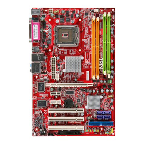
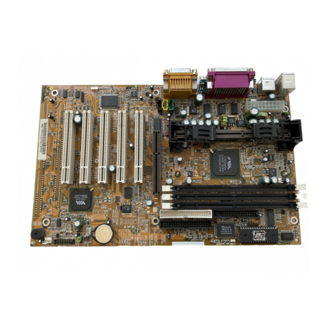
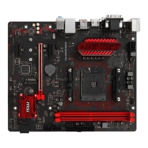
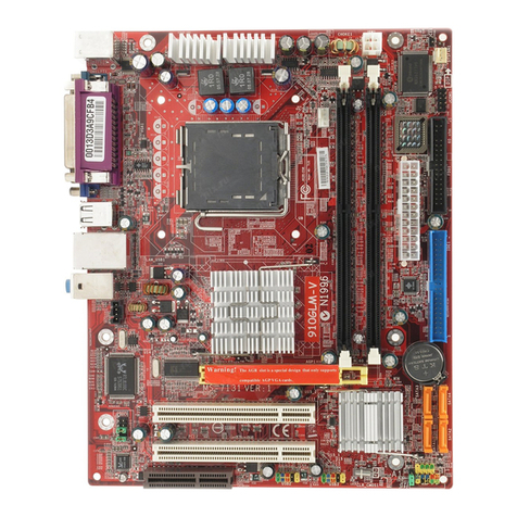
MSI G31M3-L V2 - Motherboard - Micro ATX User manual

FCC-BRadioFrequencyInterference Statement
Thisequipmenthasbeentestedand foundtocomplywiththelimitsforaclass Bdigital
device, pursuant topart15 of theFCCrules.Theselimitsaredesigned toprovide
reasonableprotectionagainstharmfulinterferencein aresidential installation.This
equipment generates,usesandcan radiateradiofrequencyenergyand,ifnotinstalled and
usedinaccordancewiththeinstructionmanual,maycauseharmful interferencetoradio
communications. However,thereisnoguarantee thatinterferencewilloccurinaparticular
installation.Ifthisequipmentdoescauseharmful interferencetoradioortelevision
reception, whichcan bedetermined byturningtheequipment off andon,theuseris
encouraged totrytocorrect theinterferencebyoneormoreofthemeasureslisted below.
nReorientorrelocatethereceivingantenna.
nIncreasetheseparation between theequipmentandreceiver.
nConnecttheequipment intoan outleton acircuitdifferent fromthattowhichthe
receiverisconnected.
nConsultthedealeroran experienced radio/televisiontechnician forhelp.
Notice 1
The changesormodificationsnotexpresslyapproved bythepartyresponsiblefor
compliancecouldvoidtheuser sauthoritytooperatetheequipment.
Notice 2
Shielded interfacecablesandA.C. powercord,if any,mustbeused inordertocomplywith
theemission limits.
VOIRLANOTICED NSTALLATIONAVANT DERACCORDERAU RESEAU.
Micro-StarInternational
MS-7529
G52-75291X1
PDFcreated withpdfFactoryProtrialversion www.pdffactory.com

CopyrightNotice
The material inthisdocumentistheintellectualpropertyofMICRO-STARINTERNATIONAL.
Wetakeeverycarein thepreparation ofthisdocument,butnoguarantee isgiven astothe
correctness ofitscontents. Ourproductsareundercontinualimprovementandwereserve
therighttomakechangeswithoutnotice.
Trademarks
All trademarksarethepropertiesoftheirrespectiveowners.
AMD®,Athlon™Athlon™XP,Thoroughbred™andDuron™areregistered trademarksof
AMD®Corporation.
Intel®and Pentium®areregistered trademarksofIntel Corporation.
PS/2andOS®/2areregistered trademarksofInternational Business MachinesCorporation.
Microsoft®isaregistered trademarkofMicrosoftCorporation.Windows®98/2000/NT/XPare
registered trademarksof Microsoft Corporation.
NVIDIA®, theNVIDIAlogo, DualNet, and nForceareregistered trademarksortrademarksof
NVIDIA®Corporation in theUnitedStatesand/orothercountries.
Netware®isaregistered trademarkofNovell, Inc.
Award®isaregistered trademarkof PhoenixTechnologiesLtd.
AMI®isaregistered trademarkofAmerican MegatrendsInc.
Kensington andMicroSaverareregisteredtrademarksoftheKensingtonTechnology
Group.
PCMCIAandCardBusareregisteredtrademarksofthePersonal ComputerMemoryCard
InternationalAssociation.
RevisionHistory
RevisionRevision HistoryDate
V1.0 First releaseMarch 2008
PDFcreated withpdfFactoryProtrialversion www.pdffactory.com

SafetyInstructions
nAlwaysreadthesafetyinstructionscarefully.
nKeep thisUserManual forfuturereference.
nKeep thisequipmentawayfromhumidity.
nLaythisequipmenton areliableflatsurfacebeforesetting itup.
nThe openingsontheenclosureareforairconvection henceprotectstheequipment
fromoverheating.Donot covertheopenings.
nMakesurethevoltageofthepowersourceandadjust properly110/220Vbefore
connecting theequipment tothepowerinlet.
nPlacethepowercordsuchawaythatpeoplecannot step onit. Donotplace
anythingoverthepowercord.
nAlwaysUnplugthePowerCordbeforeinsertinganyadd-oncardormodule.
nAll cautionsandwarningsontheequipment should benoted.
nNeverpouranyliquidintotheopeningthatcould damageorcauseelectrical shock.
nIfanyofthefollowing situationsarises, gettheequipment checked byaservice
personnel:
-Thepowercordorplugisdamaged.
-Liquidhaspenetrated intotheequipment.
-Theequipmenthasbeenexposed tomoisture.
-Theequipmentdoesnotworkwelloryoucannotget it workaccordingtoUser
Manual.
-Theequipmenthasdropped anddamaged.
-Theequipmenthasobvioussignofbreakage.
nDonotleavethisequipmentinan environmentunconditioned,storagetemperature
above60°C(140°F), itmaydamagetheequipment.
CAUTION:Dangerofexplosion ifbatteryisincorrectlyreplaced.Replace onlywith
thesameorequivalenttyperecommendedbythemanufacturer.
PDFcreated withpdfFactoryProtrialversion www.pdffactory.com

WEEE Statement
ENGLISH
Toprotect the globalenvironment and asanenvironmentalist, MSI must remindyou
that...
Underthe EuropeanUnion ("EU")Directiveon WasteElectricaland Electronic Equipment, Directive
2002/96/EC, whichtakeseffect onAugust 13, 2005, productsof "electricaland electronic equipment"
cannotbe discarded asmunicipalwasteanymoreand manufacturersofcovered electronic equipmentwill
be obligated totakebacksuchproductsatthe end oftheirusefullife.MSI will complywiththe producttake
backrequirementsat the end of lifeofMSI-branded productsthat aresoldintothe EU.You can return
theseproductstolocalcollection points.
DEUTSCH
Hinweis von MSIzurErhaltungundSchutzunsererUmwelt
Gemäß derRichtlinie2002/96/EG überElektro-undElektronik-AltgerätedürfenElektro-und
Elektronik-Altgerätenicht mehrals kommunaleAbfälleentsorgt werden.MSI hat europaweit
verschiedene Sammel-und Recyclingunternehmen beauftragt,dieindieEuropäische Union inVerkehr
gebrachten Produkte, amEndeseinesLebenszykluszurückzunehmen.Bitteentsorgen Siedieses
Produkt zumgegebenen Zeitpunkt ausschliesslichan einerlokalen AltgerätesammelstelleinIhrerNähe.
FRANÇAIS
Entant qu écologisteet afindeprotégerl environnement, MSItient àrappelerceci...
Ausujet de ladirectiveeuropéenne (EU)relativeauxdéchetsdes équipement électriqueset
électroniques, directive2002/96/EC,prenanteffet le13 août 2005, que lesproduits électriqueset
électroniquesne peuvent êtredéposésdanslesdéchargesou tout simplementmis àlapoubelle. Les
fabricantsde ces équipementsserontobligésde récupérercertainsproduitsen finde vie. MSI prendraen
comptecetteexigencerelativeauretourdesproduitsen finde vieauseinde lacommunautéeuropéenne.
Parconséquentvouspouvezretournerlocalement cesmatériels danslespointsde collecte.
РУССКИЙ
Компания MSI предпринимает активные действия по защите окружающей среды, поэтому
напоминаем вам, что....
Всоответствии сдирективой Европейского Союза (ЕС) по предотвращению загрязнения
окружающей среды использованным электрическим иэлектронным оборудованием (директива
WEEE 2002/96/EC), вступающей всилу 13 августа 2005 года, изделия, относящиеся к
электрическому иэлектронному оборудованию, не могут рассматриваться как бытовой мусор,
поэтому производители вышеперечисленного электронного оборудования обязаны принимать его
для переработки по окончании срока службы.MSI обязуется соблюдать требования по приему
продукции, проданной под маркой MSI на территории EC, впереработку по окончании срока
службы. Вы можете вернуть эти изделия вспециализированные пункты приема.
ESPAÑOL
MSIcomoempresacomprometida con laproteccióndelmedioambiente, recomienda:
Bajoladirectiva2002/96/EC delaUniónEuropea enmateriade desechosy/oequiposelectrónicos, con
fecha de rigordesde el13 de agostode 2005, losproductosclasificadoscomo"eléctricosyequipos
electrónicos"no pueden serdepositadosen loscontenedoreshabitualesde sumunicipio,losfabricantes
de equiposelectrónicos, estánobligadosahacersecargo de dichosproductosaltermino de superíodo
de vida.MSIestarácomprometido con lostérminosde recogida de susproductosvendidosen laUnión
Europea alfinalde superiodo de vida. Usted debe depositarestosproductosen elpuntolimpio
establecido porelayuntamientodesulocalidad oentregarauna empresaautorizada paralarecogidade
estosresiduos.
NEDERLANDS
Omhet milieu tebeschermen, wil MSIueraan herinneren dat….
Derichtlijnvan de EuropeseUnie(EU)met betrekking totVervuiling van Electrische en Electronische
producten (2002/96/EC), dieop 13Augustus2005inzalgaankunnenniet meerbeschouwdworden als
vervuiling.
Fabrikanten vanditsoortproductenworden verplichtomproducten retourtenemen aan heteind van hun
levenscyclus.MSIzalovereenkomstigde richtlijnhandelen voordeproducten diede merknaamMSI
dragen en verkocht zijninde EU. Dezegoederen kunnen geretourneerdwordenop lokale
inzamelingspunten.
PDFcreated withpdfFactoryProtrialversion www.pdffactory.com
SRPSKI
Dabizaštitili prirodnu sredinu,ikao preduzećekojevodiračuna ookoliniiprirodnojsredini, MSImorada
vaspodestida…
PoDirektiviEvropskeunije("EU")oodbačenojekektronskojielektričnojopremi, Direktiva2002/96/EC,
kojastupa nasnagu od 13.Avgusta2005,proizvodikoji spadajupod "elektronskuielektričnu opremu"ne
mogu višebitiodbačenikao običan otpadiproizvođačioveopremebićeprinuđenida uzmunatrag ove
proizvodena krajunjihovog uobičajenog vekatrajanja.MSI ćepoštovatizahtevopreuzimanjuovakvih
proizvodakojimajeistekao vektrajanja, koji imajuMSIoznakuikoji suprodatiuEU. Oveproizvode
možetevratitina lokalnimmestimazaprikupljanje.
POLSKI
Abychronićnasze środowiskonaturalne orazjakofirmadbającaoekologię,MSIprzypomina, że...
ZgodniezDyrektywąUnii Europejskiej("UE")dotyczącąodpadówproduktów elektrycznychi
elektronicznych(Dyrektywa2002/96/EC),którawchodziw życie13sierpnia2005, tzw. “produktyoraz
wyposażenieelektryczne ielektroniczne "niemogąbyćtraktowanejako śmiecikomunalne, takwięc
producenci tychproduktów będązobowiązanido odbieraniaichw momenciegdyprodukt jest
wycofywanyzużycia.MSIwypełniwymaganiaUE,przyjmującprodukty(sprzedawane naterenieUnii
Europejskiej)wycofywanezużycia.ProduktyMSIbędziemożna zwracaćw wyznaczonychpunktach
zbiorczych.
TÜRKÇE
Çevreci özelliğiylebilinen MSIdünyada çevreyikorumakiçinhatırlatır:
Avrupa Birliği(AB)KararnamesiElektrikveElektronikMalzemeAtığı,2002/96/ECKararnamesi altında 13
Ağustos2005 tarihinden itibaren geçerli olmak üzere, elektrikli veelektronikmalzemelerdiğeratıklargibi
çöpe atılamayacakvebu elektonikcihazların üreticileri,cihazlarınkullanımsüreleribittikten sonra ürünleri
geritoplamaklayükümlüolacaktır.Avrupa Birliğine satılan MSI markalıürünlerinkullanımsüreleri
bittiğinde MSI ürünleringerialınmasıisteğiileişbirliğiiçerisinde olacaktır. Ürünleriniziyereltoplama
noktalarına bırakabilirsiniz.
ČESKY
Záleží námna ochraněživotního prostředí-společnost MSI upozorňuje...
PodlesměrniceEvropskéunie("EU")olikvidaci elektrickýchaelektronickýchvýrobk 2002/96/EC platné
od 13. srpna 2005 jezakázáno likvidovat "elektrickéaelektronickévýrobky"vběžnémkomunálním
odpadu avýrobci elektronickýchvýrobk ,na kterésetatosměrnicevztahuje, budou povinniodebírat
takovévýrobkyzpětpo skončeníjejich životnosti.SpolečnostMSI splnípožadavkyna odebíránívýrobk
značkyMSI, prodávanýchvzemíchEU, po skončeníjejich životnosti.Tytovýrobkym žeteodevzdatv
místníchsběrnách.
MAGYAR
Annak érdekében, hogykörnyezetünket megvédjük, illetvekörnyezetvédőként fellépveazMSI
emlékezteti Önt, hogy...
AzEurópaiUnió(„EU")2005.augusztus13-ánhatálybalépő, azelektromos éselektronikus
berendezésekhulladékairólszóló2002/96/EKirányelveszerint azelektromos éselektronikus
berendezésektöbbénemkezelhetőeklakosságihulladékként, ésazilyen elektronikusberendezések
gyártóikötelesséválnakazilyen termékekvisszavételéreazokhasznos élettartamavégén.AzMSI
betartjaatermékvisszavétellelkapcsolatoskövetelményeketazMSImárkanévalatt azEU-nbelül
értékesített termékekesetében,azok élettartamánakvégén.Azilyentermékeket alegközelebbi
gyűjtőhelyreviheti.
ITALIANO
Perproteggerel ambiente,MSI, da sempreamicadellanatura, tiricorda che….
InbaseallaDirettivadell Unione Europea (EU)sulloSmaltimentodeiMateriali Elettrici ed Elettronici,
Direttiva2002/96/EC invigoredal13 Agosto2005,prodottiappartenentiallacategoriadeiMateriali
Elettrici ed Elettronici non possono piùessereeliminaticomerifiutimunicipali:iproduttorididettimateriali
saranno obbligatiaritirareogniprodottoallafine delsuo ciclodivita.MSIsi adegueràataleDirettiva
ritirando tuttiiprodottimarchiatiMSIche sono stativendutiall interno dell Unione Europea allafine del
lorociclodivita. Èpossibileportareiprodottinelpiùvicino puntodiraccolta.
PDFcreated withpdfFactoryProtrialversion www.pdffactory.com
Table of Content
English...........................1
Français.........................13
Deutsch .........................25
Русском.........................39
简体中文 ........................53
繁體中文 ........................65
日本語............................77

1
INTRODUCTION
ThankyouforchoosingtheG31M3V2Series(MS-7529v1.x)Micro-ATXmainboard.The
G31M3V2Seriesarebasedon Intel G31&Intel ICH7chipsetsforoptimalsystem
efficiency. Designed tofittheadvanced Intel CoreTM 2Duo/ CoreTM 2Quad/Pentium
Dual-CoreE2XXX andCeleron4XXX/ WolfdaleSeriesLGA775 processor, theG31M3V2
Seriesdeliverahighperformanceand professional desktop platformsolution.
Layout

2
SPECIFICATIONS
ProcessorSupport
lSupportsIntel CoreTM 2Duo/ CoreTM 2Quad/PentiumDual-CoreE2XXX andCeleron
4XXX/WolfdaleSeriesprocessorinLGA775package.
lSupports4pinCPUfan pin-headerwithFanspeedControl
lSupportsTDPMax. 95W
(Forthelatest information aboutCPU,pleasevisit:
http://global.msi.com.tw/index.php?func=cpuform)
SupportedFSB
l800/1066/ 1333MHz
Chipset
lNorthBridge:Intel G31 chipset
lSouthBridge: Intel ICH7chipset
MemorySupport
lDDR2667/800SDRAM(4GBMax)
l2DDR2DIMMs(240pin/1.8V)
(Formoreinformationon compatiblecomponents,pleasevisit:
http://global.msi.com.tw/index.php?func=testreport)
LAN(Optional)
lSupportsRealtek RTL8111C10/100/1000Mbps
lSupportsRealtek RTL8101E10/100Mbps(optional)
lCompliancewithPCI2.2
lSupportsACPIPowerManagement
Audio
lChipintegrated byRealtek ALC888
lFlexible8-channelaudiowithjack sensing
lCompliantwithVistaPremium
IDE
l1IDEportbyICH7
lSupportsUltraDMA66/100 mode
lSupportsPIO, BusMasteroperation mode
SATA
l2SATAII portsbyICH7
lSupports4SATAII devices
lSupportsstorageand datatransfersatup to3Gb/s
Floppy
l1floppyport
lSupports1FDDwith360KB, 720KB,1.2MB,1.44MBand2.88 MB

3
TPM(Optional)
lSupportsTPM
Connectors
lBackpanel
-1PS/2mouseport
-1PS/2keyboardport
-1serialport (COM1)
-1VGAport
-1parallel portsupportingSPP/EPP/ECPmode
-4USB2.0Ports
-1RJ-45LANjack
-3/6flexibleaudiojacks(optional)
lOn-BoardPinheaders/ Connectors
-2USB2.0pinheaders
-1CD-Inconnector
-1S/PDIF-Outpinheader
-1Front PanelAudiopinheader
-1serialport connector
-1TPMconnector(optional)
-1chassisintrusion switchpinheader
-1SPI Debuggingconnector
Slots
l1PCIExpress x16slot
l2PCIslots
lSupport3.3V/ 5VPCIbusInterface
Form Factor
lMicro-ATX(24.4cmX19.3cm)
Mounting
l6mountingholes
Important:
Toreachthe8-channel sound effect, the7thand8thchannelsmustbeoutputted fromfront
panel (pinheader) if youpurchasethemainboardwith3audiojacks.

4
REARPANEL
The rearpanelprovidesthefollowing connectors:
HARDWARESETUP
ThischaptertellsyouhowtoinstalltheCPU,memorymodules,andexpansioncards,as
wellashowtosetup thejumperson themainboard.It alsoprovidestheinstructionson
connecting theperipheraldevices, suchasthemouse,keyboard,etc.Whiledoingthe
installation,becarefulin holdingthecomponentsandfollowtheinstallation procedures.
CPU&CoolerInstallationProcedures forLGA775
Whenyou areinstallingtheCPU,makesuretheCPUhasacoolerattached on thetop to
preventoverheating.Meanwhile, donot forgettoapplysomethermalpasteon CPUbefore
installing theheat sink/coolerfanforbetterheatdispersion.
FollowthestepsbelowtoinstalltheCPU&coolercorrectly.Wronginstallationwillcausethe
damageof yourCPU&mainboard.
IntroductiontoLGA775CPU
The pin-padsideof LGA775CPU.
The surfaceof LGA775CPU.
1.TheCPUsockethasaplasticcap on it toprotectthecontact
fromdamage.Beforeyou haveinstalled theCPU,always
coverittoprotect thesocketpin.
2.Removethecap fromleverhingeside.
3.The pinsofsocketreveal.
4.Open theloadlever.
5.Lift theloadleverupandopen theloadplate.
6.AfterconfirmingtheCPUdirectionforcorrectmating,put
downtheCPUinthesocket housingframe. Besuretograsp

5
on theedgeof theCPUbase. Notethat thealignmentkeys
arematched.
7.VisuallyinspectiftheCPUisseated wellintothesocket. If
not, takeout theCPUwithpureverticalmotion andreinstall.
8.Covertheloadplateontothepackage.
9.Press downtheloadleverlightlyontotheloadplate,and
then securetheleverwiththehookunderretentiontab.
10.Align theholeson themainboardwiththecooler.Pushdown
thecooleruntilitsfourclipsgetwedged intotheholesof the
mainboard.
11.Press thefourhooks downtofasten thecooler.Thenrotate
thelocking switch(refertothecorrectdirection marked on it)
tolock thehooks.
12.Turnoverthemainboardtoconfirmthattheclip-endsare
correctlyinserted.
Important:
Read theCPUstatusinBIOS.
WheneverCPUisnotinstalled,alwaysprotectyourCPUsocketpin withtheplasticcap
coveredtoavoiddamaging.
Mainboardphotosshownin thissection arefordemonstrationoftheCPU/coolerinstallation
only.Theappearanceof yourmainboardmayvarydependingon themodel youpurchase.
InstallingMemoryModules
1.The memorymodulehasonlyonenotchon thecenterandwillonlyfit intheright
orientation.
2.InsertthememorymoduleverticallyintotheDIMMslot.Then pushitinuntil the
golden fingeron thememorymoduleisdeeplyinsertedintheDIMMslot.You can
barelysee thegolden fingerifthememorymoduleisproperlyinserted intheDIMM
slot.Theplasticclip at eachsideoftheDIMMslotwillautomaticallyclosewhen the
memorymoduleisproperlyseated.
3.ManuallycheckifthememorymodulehasbeenlockedinplacebytheDIMMslot
clipsatthesides.
Volt
Notch

6
Important:
DDR2memorymodulesarenot interchangeablewithDDR andtheDDR2standardisnot
backwardscompatible. Youshouldalwaysinstall DDR2memorymodulesintheDDR2
DIMMslots.
Toenablesuccessful systemboot-up,alwaysinsert thememorymodulesintotheDIMM1
first.
ATX24-PinPowerConnector:ATX1
Thisconnectorallowsyoutoconnect an ATX24-pinpowersupply.
ToconnecttheATX24-pinpowersupply,makesuretheplugofthe
powersupplyisinsertedintheproperorientationand thepinsare
aligned.Thenpushdownthepowersupplyfirmlyintothe
connector.
Youmayusethe20-pinATXpowersupplyasyoulike.If you liketo
usethe20-pinATXpowersupply,pleaseplug yourpowersupply
alongwithpin1&pin13 (refertotheimageat therighthand).
GND
GND
GND
PS-ON#
GND
+3.3V
-12V
+3.3V
+3.3V
+3.3V
+5V
+5V
+5V
+5V
+5V
Res
PWROK
GND
GND
GND
GND
5VSB
+12V
+12V
ATX12VPowerConnector:JPW1
This12Vpowerconnectorisused toprovidepowertotheCPU.
GND
GND
+12V
+12V
Important:
Makesurethat all theconnectorsareconnectedtoproperATXpowersuppliestoensure
stableoperation ofthemainboard.
Powersupplyof 350watts(andabove)ishighlyrecommended forsystemstability.
ATX12Vpowerconnectionshouldbegreaterthan 18A.
FloppyDisk DriveConnector:FDD1
Thisconnectorsupports360 KB,720KB,1.2MB,1.44 MB
or2.88MBfloppydiskdrive.
IDEConnector:IDE1
ThisconnectorsupportsIDEharddiskdrives,optical diskdrivesandother
IDEdevices.
Important:
IfyouinstalltwoIDEdeviceson thesamecable,youmust configurethe
drivestocableselectmodeorseparatelytomaster/ slavemodebysetting
jumpers. RefertoIDEdevicedocumentationsupplied bythevendorsfor
jumpersettinginstructions.
SerialATAConnector:SATA1/SATA2/ SATA3/
SATA4
Thisconnectorisahigh-speedSerialATAinterfaceport. Eachconnector
can connect tooneSerialATAdevice.

7
Important:
Pleasedonot foldtheSerial ATAcableinto90-degree angle. Otherwise,
dataloss mayoccurduringtransmission.
FanPowerConnectors:CPUFAN1,
SYSFAN1, SYSFAN2
The fan powerconnectorssupport systemcoolingfanwith+12V.
Whenconnectingthewiretotheconnectors,alwaysnotethat the
redwireisthepositiveandshould beconnectedtothe+12V;the
blackwireisGroundandshouldbeconnected toGND.Ifthe
mainboardhasaSystemHardwareMonitorchipseton-board,you
mustuseaspeciallydesigned fanwithspeedsensortotake
advantageoftheCPUfancontrol.
GND
+12V
Sensor
Control
GND
+12V
Sensor
GND
+12V
Sensor
ChassisIntrusionConnector:JCI1
Thisconnectorconnectstothechassisintrusion switchcable. Ifthe
chassisisopened,thechassisintrusionmechanismwillbe
activated.Thesystemwill recordthisstatusandshowawarning
messageonthescreen.Toclearthewarning,youmust enterthe
BIOSutilityandcleartherecord.
CINTRU
GND
2
1
S/PDIF-OutConnector:JSPD1
ThisconnectorisusedtoconnectS/PDIF (Sony&PhilipsDigital
InterconnectFormat)interfacefordigitalaudiotransmission.
GND
VCC
SPDIF
CD-InConnector:CD_IN1
Thisconnectorisprovided forexternal audioinput.
GND
L R
JFP2
Power
LED
Speaker
2
8
1
7
FrontPanel Connectors:JFP1,
JFP2
Theseconnectorsareforelectricalconnection tothe
front panel switchesandLEDs.TheJFP1iscompliant
withIntel FrontPanel I/OConnectivityDesignGuide.
JFP1
HDD
LED
Reset
Switch
Power
Switch
Power
LED
1
9
10
2
+
+
+
-
-
-
FrontUSBConnector:JUSB1,
JUSB2
Thisconnector, compliantwithIntel I/OConnectivity
DesignGuide,isideal forconnectinghigh-speedUSB
interfaceperipheralssuchasUSB HDD, digitalcameras,
MP3players,printers,modemsandthelike.
N.C.(10)
(2)VCC
USB1-
USB1+
GND
(1)VCC
USB0-
USB0+
GND
Key,nopin(9)

8
FrontPanelAudioConnector:
JAUD1
Thisconnectorallowsyoutoconnectthefront panel
audioandiscompliantwithIntel FrontPanel I/O
ConnectivityDesignGuide.
(2)GND
VCC5
MIC2_JD
NC
(1)MIC_L
Line-out_R
Line-out_L(9)
Line_JD(10)
(2)GND
MIC_R FronttoSense
SPIDebuggingConnector:JSPI1
Thisconnectorisforinternal debuggingonly.
Serial PortConnector:JCOM1
Thisconnectorisa16550Ahighspeedcommunication
portthatsends/receives16 bytesFIFOs.You can attach
aserialdevicetoit.
Key,nopin
SIN
DTR
DSR
CTS
DCD
SOUT
GND
RTS
RI
(10)
(2)
(1) (9)
TPMModuleconnector:
JTPM1(Optional)
ThisconnectorconnectstoaTPM(Trusted Platform
Module)module.PleaserefertotheTPMsecurity
platformmanualformoredetailsandusages.
KEY
GND
GND
14
3Vdual/ 3V_STB
2
VCC3
SIRQ
VCC5
LCLK
1
LRST#
LAD0
LAD1
LAD2
LAD3
LFRAME#
13
ClearCMOSJumper:JBAT1
ThereisaCMOSRAMonboardthathasapowersupply
froman external batterytokeepthedataofsystem
configuration. WiththeCMOSRAM,thesystemcan
automaticallybootOSeverytimeitisturned on. If you
wanttoclearthesystemconfiguration, setthejumperto
cleardata.
KeepData
ClearData
22 2
33 3
11 1
Important:
YoucanclearCMOSbyshorting2-3pinwhilethesystemisoff.Thenreturnto1-2pin
position.Avoid clearingtheCMOSwhilethesystemison; itwill damagethemainboard.
PCI(Peripheral ComponentInterconnect) Express Slot
The PCIExpress slot supportsthePCIExpress interfaceexpansioncard.
The PCIExpress x16 slotsupportsup to4.0GB/stransferrate.
PCI(Peripheral ComponentInterconnect) Slot

9
The PCIslotsupportsLANcard,SCSIcard, USBcard,andotheradd-on cardsthat
complywithPCI specifications.
Important:
Whenaddingorremovingexpansioncards,makesurethatyou unplug thepowersupply
first. Meanwhile, readthedocumentation fortheexpansion cardtoconfigureany
necessaryhardwareorsoftwaresettingsfortheexpansioncard, suchasjumpers,
switchesorBIOSconfiguration.
PCIInterruptRequestRouting
The IRQ,acronymofinterrupt requestlineandpronounced I-R-Q,arehardwarelinesover
whichdevicescansendinterrupt signalstothemicroprocessor.ThePCI IRQpinsare
typicallyconnected tothePCIbuspinsasfollows:
Order1 Order2 Order3 Order4
PCI Slot1 INTA# INT B# INT C# INT D#
PCI Slot2 INT B# INT C# INT D# INTA#
BIOSSetup
PoweronthecomputerandthesystemwillstartPOST(PowerOnSelfTest)process.When
themessagebelowappearson thescreen,press <DEL> keytoenterSetup.
PressDELtoenterSETUP
Ifthemessagedisappearsbeforeyourespondand you stillwishtoenterSetup, restartthe
systembyturning it OFF andOnorpressingtheRESETbutton.You mayalsorestart the
systembysimultaneouslypressing <Ctrl>,<Alt>,and <Delete> keys.
MainPage

10
Standard CMOSFeatures
Usethismenuforbasicsystemconfigurations, suchastime, dateetc.
Advanced BIOSFeatures
Usethismenutosetuptheitemsofspecialenhanced features.
IntegratedPeripherals
Usethismenutospecifyyoursettingsforintegrated peripherals.
PowerManagementSetup
Usethismenutospecifyyoursettingsforpowermanagement.
H/W Monitor
Thisentryshowsthestatusof yourCPU,fan,warning overallsystemstatus.
BIOSSettingPassword
Usethismenutoset BIOSsetting Password.
Cell Menu
Usethismenutospecifyyoursettingsforfrequency/voltagecontrol.
Load Fail-SafeDefaults
UsethismenutoloadtheBIOSdefaultvaluesthatarefactorysettingsforsystem
operations.
LoadOptimizedDefaults
Usethismenutoloadfactorydefault settingsintotheBIOSforstablesystemperformance
operations.
Save&ExitSetup
SavechangestoCMOSandexit setup.
ExitWithoutSaving
Abandonall changesand exitsetup.
Cell Menu

11
CurrentCPUFrequency
It showsthecurrent frequencyofCPU.Read-only.
CurrentDRAMFrequency
It showsthecurrent frequencyof Memory. Read-only.
Intel EIST
TheEnhanced Intel SpeedStep technologyallowsyou tosettheperformancelevelofthe
microprocessorwhetherthecomputerisrunningon batteryorACpower.Ifyou intentto
adjusttheCPURatio,pleaseset “Disabled”inthisfield.Thisfield willappearafteryou
installed theCPUwhichsupport speedstep technology.
AdjustCPUFSBFrequency(MHz)
WhenAutoDetect CPUFrequencyitemset to[Disable], thisitemwillallowyou tomanually
adjust theCPUFSB frequency.
Adjusted CPUFrequency
It showstheadjusted CPUfrequency(FSBxRatio). Read-only.
AdvanceDRAMConfiguration>DRAMCAS#Latency
The fieldcontrolstheCASlatency,whichdeterminesthetimingdelaybeforeDRAMstartsa
read commandafterreceivingit. [2T] increasessystemperformancewhile[2.5T] provides
morestablesystemperformance.Setting to[BySPD]enablesDRAMCAS#Latency
automaticallytobedetermined byBIOSbasedon theconfigurationson theSPD(Serial
PresenceDetect)EEPROMontheDRAMmodule.
FSB/MemoryRatio
WhenAutoDetect DRAMFrequencyitemset to[Disable], thisitemwill allowyouto
manuallyadjust theFSB/Ratioofthememory.
AdjustedDDRMemoryFrequency
It showstheadjusted DDRMemoryfrequency. Read-only.
AdjustPCI-E Frequency(MHz)
Thisitemallowsyou toselectthePCI Express clockfrequency(inMHz)andoverclockby
adjustingthePCI Express clocktoahigherfrequency.
AutoDisableDIMM/PCI Frequency
Whenset to[Enabled], thesystemwill remove(turnoff)clocksfromemptyDIMMandPCI
slotstominimizetheelectromagneticinterference(EMI).
SpreadSpectrum
Whenthemotherboard’sclockgeneratorpulses,theextremevalues(spikes)ofthepulses
createEMI (ElectromagneticInterference).TheSpread SpectrumfunctionreducestheEMI
generated bymodulatingthepulsessothatthespikesofthepulsesarereducedtoflatter
curves.Ifyoudonot haveanyEMIproblem,leavethesettingatDisabled foroptimalsystem
stabilityandperformance.Butif youareplagued byEMI, set toEnabled forEMI reduction.
RemembertodisableSpreadSpectrumif you areoverclockingbecauseevenaslight jitter
can introduceatemporaryboostin clock speedwhichmayjust causeyouroverclocked
processortolockup.
Important:
IfyoudonothaveanyEMIproblem,leavethesettingat[Disabled] foroptimal system
stabilityandperformance.Butif youareplagued byEMI, selectthevalueof Spread
SpectrumforEMI reduction.

12
The greatertheSpreadSpectrumvalueis, thegreatertheEMIisreduced,andthesystem
willbecomeless stable. Forthemost suitableSpreadSpectrumvalue,pleaseconsultyour
local EMI regulation.
RemembertodisableSpreadSpectrumif you areoverclockingbecauseevenaslight jitter
can introduceatemporaryboostin clock speedwhichmayjust causeyouroverclocked
processortolockup.
LoadOptimizedDefaults
Youcanloadthedefault valuesprovided bythemainboardmanufacturerforthestable
performance.

13
INTRODUCTION
Flicitations,vousvenezd’acqu rirunecartemèredess riesMicro-ATXG31M3V2
(MS-7529v1.x).LesG31M3V2s riessontbas essurleschipsetsIntel®G31etIntel®
ICH7offrantunsystèmetrèsperformant.LacartefonctionneavecleprocesseurLGA775
deIntel®CoreTM 2Duo/CoreTM 2Quad/PentiumDual-CoreE2XXX etCeleron 4XXX/
Wolfdales ries, less riesG31M3V2sonttrèsperformanteset offrentunesolution adapt e
tantauxprofessionnelsqu’auxparticuliers.
Sch ma

14
SPÉCIFICITÉS
ProcesseursSupport s
lSupportelesprocesseursdes rieIntel®CoreTM 2Duo/ CoreTM 2Quad/ Pentium
Dual-CoreE2XXX et Celeron 4XXX/WolfdaledanslepaquetLGA775.
lSupporteun connecteurde4pinsdu ventilateurdeCPUavecleContrôleurdelavitesse
du ventilateur.
lSupporteTDPMax. 95W
(Pourplusd’informationssurleCPU, veuillezvisiter:
http://global.msi.com.tw/index.php?func=cpuform)
FSBsupport
l800/1066/ 1333MHz
Chipset
lNorthBridge:chipset Intel®G31
lSouthBridge: chipsetIntel®ICH7
MmoireSupport e
lDDR2667/800SDRAM(4GBMax)
l2DDR2DIMMs(240pin/1.8V)
(Pourplusd’informationssurlescomposantscompatibles, veuillezvisiter:
http://global.msi.com.tw/index.php?func=testreport)
LAN(Optionnel)
lSupporteRealtek®RTL8111C10/100/1000Mbps
lSupporteRealtek®RTL8101E10/100 Mbps(optionnel)
lCompatibleavecPCI 2.2
lSupporteACPIPowerManagement
Audio
lPuceint gr eparRealtek®ALC888
l8-canauxaudioflexibleavecd tection dejack
lCompliantwithVistaPremium
IDE
l1portIDEparICH7
lSupportelemodeUltraDMA66/100
lSupportelesmodesd’op ration PIO, BusMaster
SATA
l2portsSATAII parICH7
lSupporte4p riph riquesSATAII
lSupportelestockageetuntauxdetransfertjusqu’à 3Gb/s
Disquette
l1portdedisquette
lSupporte1FDD avec360KB,720KB, 1.2MB,1.44MBet 2.88MB.
This manual suits for next models
1
Table of contents
Languages:
Other MSI Motherboard manuals

MSI
MSI K7 Master MS-6341 User manual

MSI
MSI MS-6532 User manual

MSI
MSI MS-7067 User manual

MSI
MSI MS-9803 User manual

MSI
MSI MS7797 User manual

MSI
MSI A55M-E45 V2 User manual

MSI
MSI X99A GAMING PRO CARBON User manual

MSI
MSI MS-7071 User manual

MSI
MSI H310M PRO-VH PLUS User manual

MSI
MSI K8N Neo4-FX User manual