MSI H410M PRO User manual

1
<變數 1> Contents
Contents
Safety Information ...........................................................................................2
Specifications ...................................................................................................3
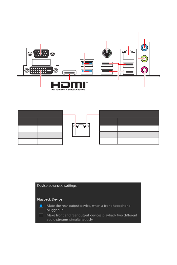
Rear I/O Panel .................................................................................................7
LAN Port LED Status Table........................................................................................7
Overview of Components ................................................................................8
CPU Socket.................................................................................................................9
DIMM Slots................................................................................................................10
M2_1~2: M.2 Slots ...................................................................................................10
PCI_E1~2: PCIe Expansion Slots..............................................................................11
SATA1~4: SATA 6Gb/s Connectors...........................................................................11
JFP1, JFP2: Front Panel Connectors.......................................................................12
JAUD1: Front Audio Connector ................................................................................12
ATX_PWR1, CPU_PWR1: Power Connectors...........................................................13
JUSB1: USB 2.0 Connector ......................................................................................14
JUSB2: USB 3.2 Gen 1 5Gbps Connector.................................................................14
CPU_FAN1, SYS_FAN1: Fan Connectors.................................................................15
JTPM1: TPM Module Connector...............................................................................15
JCI1: Chassis Intrusion Connector...........................................................................16
JCOM1: Serial Port Connector.................................................................................16
JBAT1: Clear CMOS (Reset BIOS) Jumper...............................................................17
EZ Debug LED...........................................................................................................17
JRGB1: RGB LED connector (H410M PRO) ..............................................................18
JRAINBOW1: Addressable RGB LED connector (H410M PRO) ...............................18
UEFI BIOS .......................................................................................................19
BIOS Setup................................................................................................................20
Entering BIOS Setup.................................................................................................20
Resetting BIOS..........................................................................................................20
Updating BIOS...........................................................................................................21
Installing OS, Drivers & Utilities ................................................................... 22
Installing Windows®10..............................................................................................22
Installing Drivers......................................................................................................22
Installing Utilities .....................................................................................................22
Thank you for purchasing the MSI®H410M PRO/ H410M-A
PRO/ H410M PRO-VH motherboard. This User Guide gives
information about board layout, component overview, BIOS
setup and software installation.

2Safety Information
Safety Information
∙The components included in this package are prone to damage from electrostatic
discharge (ESD). Please adhere to the following instructions to ensure successful
computer assembly.
∙Ensure that all components are securely connected. Loose connections may cause
the computer to not recognize a component or fail to start.
∙Hold the motherboard by the edges to avoid touching sensitive components.
∙It is recommended to wear an electrostatic discharge (ESD) wrist strap when
handling the motherboard to prevent electrostatic damage. If an ESD wrist strap is
not available, discharge yourself of static electricity by touching another metal object
before handling the motherboard.
∙Store the motherboard in an electrostatic shielding container or on an anti-static
pad whenever the motherboard is not installed.
∙Before turning on the computer, ensure that there are no loose screws or metal
components on the motherboard or anywhere within the computer case.
∙Do not boot the computer before installation is completed. This could cause
permanent damage to the components as well as injury to the user.
∙If you need help during any installation step, please consult a certified computer
technician.
∙Always turn off the power supply and unplug the power cord from the power outlet
before installing or removing any computer component.
∙Keep this user guide for future reference.
∙Keep this motherboard away from humidity.
∙Make sure that your electrical outlet provides the same voltage as is indicated on
the PSU, before connecting the PSU to the electrical outlet.
∙Place the power cord such a way that people can not step on it. Do not place
anything over the power cord.
∙All cautions and warnings on the motherboard should be noted.
∙If any of the following situations arises, get the motherboard checked by service
personnel:
▪Liquid has penetrated into the computer.
▪The motherboard has been exposed to moisture.
▪The motherboard does not work well or you can not get it work according to
user guide.
▪The motherboard has been dropped and damaged.
▪The motherboard has obvious sign of breakage.
∙Do not leave this motherboard in an environment above 60°C (140°F), it may
damage the motherboard.

3
Safety Information Specications
Specifications
CPU
Supports 10th Gen Intel® Core™ and Pentium® Gold / Celeron®
processors for LGA 1200 socket*
* Please go to www.intel.com for more compatibility
information.
* Onboard graphics output are disabled when using F SKU
processors.
Chipset Intel® H410 chipset
Memory
∙2x DDR4 memory slots, support up to 64GB*
∙Intel® Core™ i7/ i9
▪Supports up to DDR4 2933 MHz
∙Intel® Core™ i5 and below
▪Supports up to DDR4 2666 MHz
∙Supports Dual-Channel mode
∙Supports non-ECC, un-buffered memory
∙Supports Intel® Extreme Memory Profile (XMP)
* Please refer www.msi.com for more information on
compatible memory.
Expansion Slots
∙1x PCIe 3.0 x16 slot (From CPU)
∙1x PCIe 3.0 x1 slot (From PCH)
∙1x M.2 slot with E key for WiFi module only
Onboard
Graphics
∙1x VGA port, supports a maximum resolution of 2048x1536
@50Hz, 2048x1280 @60Hz, 1920x1200 @60Hz (H410M PRO &
H410M PRO-VH)
∙1x DVI-D port, supports a maximum resolution of 1920x1200
@60Hz (H410M PRO & H410M-A PRO)
∙1x HDMI™ 1.4 port, supports a maximum resolution of
4096x2160 @30Hz
Audio Realtek® ALC892/ ALC897 Codec
∙7.1-Channel High Definition Audio
LAN 1x Intel® I219V Gigabit LAN controller
Continued on next page

4Specications
Continued from previous page
Storage
Intel® H410 Chipset
∙4x SATA 6Gb/s ports*
∙1x M.2 slot (Key M)
▪M2_1 supports up to PCIe 3.0 x4 and SATA 6Gb/s, 2242/
2260/ 2280 storage devices*
* SATA4 will be unavailable when installing M.2 SATA SSD in
the M.2 slot.
USB
Intel® H410 Chipset
∙4x USB 3.2 Gen 1 5Gbps ports (2 Type-A ports on the back
panel, 2 ports available through the internal USB 3.2 Gen 1
5Gbps connector)
∙6x USB 2.0 ports (4 Type-A ports on the back panel, 2 ports
available through the internal USB 2.0 connector)
Internal
Connectors
∙1x 24-pin ATX main power connector
∙1x 8-pin ATX 12V power connector
∙4x SATA 6Gb/s connectors
∙1x USB 2.0 connector (supports additional 2 USB 2.0 ports)
∙1x USB 3.2 Gen1 5Gbps connector (supports additional 2
USB 3.2 Gen1 5Gbps ports)
∙1x 4-pin CPU fan connector
∙1x 4-pin system fan connector
∙1x Front panel audio connector
∙2x Front panel connectors
∙1x Serial port connector
∙1x TPM module connector
∙1x Chassis Intrusion connector
∙1x Clear CMOS jumper
∙1x 4-pin RGB LED connector (H410M PRO)
∙1x 3-pin RAINBOW LED connector (H410M PRO)
∙4x EZ Debug LED
Continued on next page

5
Specications Specications
Continued from previous page
Back Panel
Connectors
∙1x VGA port (H410M PRO & H410M PRO-VH)
∙1x DVI-D port (H410M PRO & H410M-A PRO)
∙1x HDMI port
∙2x USB 3.2 Gen1 5Gbps Type-A ports
∙1x PS/2 keyboard/ mouse combo port
∙4x USB 2.0 Type-A ports
∙1x LAN (RJ45) port
∙3x audio jacks
I/O Controller NUVOTON NCT5887D Controller Chip
Hardware
Monitor
∙CPU/System temperature detection
∙CPU/System fan speed detection
∙CPU/System fan speed control
Form Factor ∙Micro-ATX Form Factor
∙9.3 in. x 7.5 in. (23.6 cm x 19.0 cm)
BIOS Features
∙1x 128 Mb flash
∙UEFI AMI BIOS
∙Multi-language
Software
∙Drivers
∙DRAGON CENTER
∙CPU-Z MSI GAMING
∙Intel® Extreme Tuning Utility
∙Google Chrome™, Google Toolbar, Google Drive
∙Norton™ Internet Security Solution
Continued on next page

6Specications
Continued from previous page
Dragon Center
Features
∙LAN Manager
∙Mystic Light (H410M PRO)
∙User Scenario
∙Hardware Monitor
∙True Color
∙Live Update
∙DPC Latency Tuner
∙Speed Up
∙Smart Tool
∙Super Charger
Please refer to http://
download.msi.com/manual/
mb/DRAGONCENTER2.pdf for
more details.

7
Specications Rear I/O Panel
Rear I/O Panel
Link/ Activity LED
Status Description
Off No link
Yellow Linked
Blinking Data activity
Speed LED
Status Description
Off 10 Mbps connection
Green 100 Mbps connection
Orange 1 Gbps connection
LAN Port LED Status Table
PS/2 Mouse/
Keyboard
LAN
USB 2.0 Type-A
USB 3.2 Gen 1
5Gbps Type-A
Mic-in
Line-in
Line-out
Audio 7.1-channel Configuration
To configure 7.1-channel audio, you have to connect front audio I/O module to JAUD1
connector and follow the below steps.
1. Click on the Realtek HD Audio Manager > Advanced Settings to open the dialog
below.
2. Select Mute the rear output device, when a front headphone plugged in.
3. Plug your speakers to audio jacks on rear and front I/O panel. When you plug into
a device at an audio jack, a dialogue window will pop up asking you which device
is current connected.
(H410M PRO &
H410M PRO-VH)
VGA
DVI-D
(H410M PRO &
H410M-A PRO)

8Overview of Components
Overview of Components
JCOM1
* Distance from the center of the CPU to the nearest DIMM slot.
SYS_FAN1
CPU_FAN1
CPU Socket
JARINBOW1
(H410M PRO)
M2_2
PCI_E2
PCI_E1
JBAT1
DIMMA1
DIMMB1
JTPM1
M2_1
SATA3
SATA4
SATA2
SATA1
JAUD1
ATX_PWR1
CPU_PWR1
JUSB2
JCI1
JUSB1
JFP2
JFP1
JRGB1
(H410M PRO)
50.89mm*

9
Overview of Components Overview of Components
CPU Socket
Please install the CPU into the CPU socket as shown below.
⚠
Important
∙
Always unplug the power cord from the power outlet before installing or removing
the CPU.
∙
Please retain the CPU protective cap after installing the processor. MSI will deal
with Return Merchandise Authorization (RMA) requests if only the motherboard
comes with the protective cap on the CPU socket.
∙
When installing a CPU, always remember to install a CPU heatsink. A CPU heatsink
is necessary to prevent overheating and maintain system stability.
∙
Conrm that the CPU heatsink has formed a tight seal with the CPU before booting
your system.
∙
Overheating can seriously damage the CPU and motherboard. Always make sure
the cooling fans work properly to protect the CPU from overheating. Be sure to apply
an even layer of thermal paste (or thermal tape) between the CPU and the heatsink to
enhance heat dissipation.
∙
Whenever the CPU is not installed, always protect the CPU socket pins by covering
the socket with the plastic cap.
∙
If you purchased a separate CPU and heatsink/ cooler, Please refer to the docu-
mentation in the heatsink/ cooler package for more details about installation.
1
4
6
5
78
9
3
2

10 Overview of Components
DIMM Slots
Please install the memory module into the DIMM slot as shown below.
⚠
Important
∙
Always insert memory modules in the DIMMA1 slot rst.
∙
To ensure system stability for Dual channel mode, memory modules must be of the
same type, number and density.
∙
Some memory modules may operate at a lower frequency than the marked value
when overclocking due to the memory frequency operates dependent on its Serial
Presence Detect (SPD). Go to BIOS and nd the DRAM Frequency to set the memory
frequency if you want to operate the memory at the marked or at a higher frequency.
∙
It is recommended to use a more ecient memory cooling system for full DIMMs
installation or overclocking.
∙
The stability and compatibility of installed memory module depend on installed
CPU and devices when overclocking.
∙
Please refer www.msi.com for more information on compatible memory.
1
12
3
3
2
M2_1~2: M.2 Slots
Please install the M.2 device into the M.2 slot as shown below.
1
3
Standoff
Supplied
M.2 screw 30º30º
2

11
Overview of Components Overview of Components
PCI_E1~2: PCIe Expansion Slots
⚠
Important
∙
When adding or removing expansion cards, always turn o the power supply and
unplug the power supply power cable from the power outlet. Read the expansion
card’s documentation to check for any necessary additional hardware or software
changes.
∙
If you install a large and heavy graphics card, you need to use a tool such as MSI
Gaming Series Graphics Card Bolster to support its weight to prevent deformation
of the slot.
PCI_E1: PCIe 3.0 x16 slot (CPU lanes)
PCI_E2: PCIe 3.0 x1 slot (PCH lanes)
SATA1~4: SATA 6Gb/s Connectors
These connectors are SATA 6Gb/s interface ports. Each connector can connect to one
SATA device.
SATA3
SATA4
SATA1
SATA2
⚠
Important
∙
Please do not fold the SATA cable at a 90-degree angle. Data loss may result
during transmission otherwise.
∙
SATA cables have identical plugs on either sides of the cable. However, it is
recommended that the at connector be connected to the motherboard for space
saving purposes.
∙
SATA4 will be unavailable when installing M.2 SATA SSD in the M.2 slot.

12 Overview of Components
JFP1, JFP2: Front Panel Connectors
These connectors connect to the switches and LEDs on the front panel.
1
2 10
9
+
+
+- --
-
+
Power LED
HDD LED Reset Switch
Reserved
Power Switch 1 HDD LED + 2 Power LED +
3 HDD LED - 4 Power LED -
5 Reset Switch 6 Power Switch
7 Reset Switch 8 Power Switch
9 Reserved 10 No Pin
JFP2 1
+
+-
-
Speaker
Buzzer 1 Speaker - 2 Buzzer +
3 Buzzer - 4 Speaker +
HDD LED
RESET SW
HDD LED HDD LED -
HDD LED +
POWER LED -
POWER LED +
POWER LED
JFP1
JAUD1: Front Audio Connector
This connector allow you to connect audio jacks on the front panel.
1
2 10
9
1 MIC L 2 Ground
3 MIC R 4 NC
5 Head Phone R 6 MIC Detection
7 SENSE_SEND 8 No Pin
9 Head Phone L 10 Head Phone Detection

13
Overview of Components Overview of Components
ATX_PWR1, CPU_PWR1: Power Connectors
These connectors allow you to connect an ATX power supply.
⚠
Important
Make sure that all the power cables are securely connected to a proper ATX power
supply to ensure stable operation of the motherboard.
24
131
12
ATX_PWR1
1 +3.3V 13 +3.3V
2 +3.3V 14 -12V
3 Ground 15 Ground
4 +5V 16 PS-ON#
5 Ground 17 Ground
6 +5V 18 Ground
7 Ground 19 Ground
8 PWR OK 20 Res
9 5VSB 21 +5V
10 +12V 22 +5V
11 +12V 23 +5V
12 +3.3V 24 Ground
5
41
8
CPU_PWR1
1 Ground 5 +12V
2 Ground 6 +12V
3 Ground 7 +12V
4 Ground 8 +12V

14 Overview of Components
JUSB2: USB 3.2 Gen 1 5Gbps Connector
This connectors allow you to connect USB 3.2 Gen 1 5Gbps ports on the front panel.
1
10 11
20
1 Power 11 USB2.0+
2 USB3_RX_DN 12 USB2.0-
3 USB3_RX_DP 13 Ground
4 Ground 14 USB3_TX_C_DP
5 USB3_TX_C_DN 15 USB3_TX_C_DN
6 USB3_TX_C_DP 16 Ground
7 Ground 17 USB3_RX_DP
8 USB2.0- 18 USB3_RX_DN
9 USB2.0+ 19 Power
10 Ground 20 No Pin
⚠
Important
Note that the Power and Ground pins must be connected correctly to avoid possible
damage.
JUSB1: USB 2.0 Connector
These connectors allow you to connect USB 2.0 ports on the front panel.
⚠
Important
∙
Note that the VCC and Ground pins must be connected correctly to avoid possible
damage.
∙
In order to recharge your iPad,iPhone and iPod through USB ports, please install
MSI® DRAGON CENTER utility.
1
2 10
9
1 VCC 2 VCC
3 USB0- 4 USB1-
5 USB0+ 6 USB1+
7 Ground 8 Ground
9 No Pin 10 NC

15
Overview of Components Overview of Components
⚠
Important
You can adjust fan speed in BIOS > Hardware Monitor.
CPU_FAN1, SYS_FAN1: Fan Connectors
PWM Mode fan connectors provide constant 12V output and adjust fan speed with
speed control signal. When you plug a 3-pin (Non-PWM) fan to a fan connector in
PWM mode, the fan speed will always maintain at 100%, which might create a lot of
noise.
1
PWM Mode pin definition
1 Ground 2 +12V
3 Sense 4 Speed Control Signal
Connector Default fan
mode Max. current Max.
power
CPU_FAN1 PWM mode 1A 12W
SYS_FAN1 DC mode 1A 12W
1
DC Mode pin definition
1 Ground 2 Voltage Control
3 Sense 4 NC
1
212
11
1 SPI Power 2 SPI Chip Select
3
Master In Slave Out (SPI
Data)
4
Master In Slave In (SPI
Data)
5 Reserved 6 SPI Clock
7 Ground 8 SPI Reset
9 Reserved 10 No Pin
11 Reserved 12 Interrupt Request
JTPM1: TPM Module Connector
This connector is for TPM (Trusted Platform Module). Please refer to the TPM
security platform manual for more details and usages.

16 Overview of Components
JCI1: Chassis Intrusion Connector
This connector allows you to connect the chassis intrusion switch cable.
Normal
(default) Trigger the chassis
intrusion event
Using chassis intrusion detector
1. Connect the JCI1 connector to the chassis intrusion switch/ sensor on the
chassis.
2. Close the chassis cover.
3. Go to BIOS > SETTINGS > Security > Chassis Intrusion Configuration.
4. Set Chassis Intrusion to Enabled.
5. Press F10 to save and exit and then press the Enter key to select Yes.
6. Once the chassis cover is opened again, a warning message will be displayed on
screen when the computer is turned on.
Resetting the chassis intrusion warning
1. Go to BIOS > SETTINGS > Security > Chassis Intrusion Configuration.
2. Set Chassis Intrusion to Reset.
3. Press F10 to save and exit and then press the Enter key to select Yes.
JCOM1: Serial Port Connector
This connector allows you to connect the optional serial port with bracket.
1
2 10
9
1 DCD 2 SIN
3 SOUT 4 DTR
5 Ground 6 DSR
7 RTS 8 CTS
9 RI 10 No Pin

17
Overview of Components Overview of Components
JBAT1: Clear CMOS (Reset BIOS) Jumper
There is CMOS memory onboard that is external powered from a battery located on
the motherboard to save system configuration data. If you want to clear the system
configuration, set the jumpers to clear the CMOS memory.
Keep Data
(default) Clear CMOS/ Reset
BIOS
Resetting BIOS to default values
1. Power off the computer and unplug the power cord.
2. Use a jumper cap to short JBAT1 for about 5-10 seconds.
3. Remove the jumper cap from JBAT1.
4. Plug the power cord and power on the computer.
EZ Debug LED
These LEDs indicate the status of the motherboard.
CPU - indicates CPU is not detected or fail.
DRAM - indicates DRAM is not detected or fail.
VGA - indicates GPU is not detected or fail.
BOOT - indicates booting device is not detected or fail.

18 Overview of Components
JRGB1: RGB LED connector (H410M PRO)
The JRGB connector allows you to connect the 5050 RGB LED strips 12V.
⚠
Important
∙
The JRGB connector supports up to 2 meters continuous 5050 RGB LED strips
(12V/G/R/B) with the maximum power rating of 3A (12V).
∙
Always turn o the power supply and unplug the power cord from the power outlet
before installing or removing the RGB LED strip.
∙
Please use MSI’s software to control the extended LED strip.
JRAINBOW1: Addressable RGB LED connector (H410M PRO)
The JRAINBOW connector allows you to connect the WS2812B Individually
Addressable RGB LED strips 5V.
⚠
CAUTION
Do not connect the wrong type of LED strips. The JRGB connector and the JRAINBOW
connector provide different voltages, and connecting the 5V LED strip to the JRGB
connector will result in damage to the LED strip.
⚠
Important
∙
The JRAINBOW connector supports up to 75 LEDs WS2812B Individually Address-
able RGB LED strips (5V/Data/Ground) with the maximum power rating of 3A (5V). In
the case of 20% brightness, the connector supports up to 200 LEDs.
∙
Always turn o the power supply and unplug the power cord from the power outlet
before installing or removing the RGB LED strip.
∙
Please use MSI’s software to control the extended LED strip.
11 +12V 2 G
3 R 4 B
11 +5V 2 Data
3 No Pin 4 Ground

19
Overview of Components UEFI BIOS
UEFI BIOS
MSI UEFI BIOS is compatible with UEFI (Unified Extensible Firmware Interface)
architecture. UEFI has many new functions and advantages that traditional BIOS
cannot achieve, and it will completely replace BIOS in the future. The MSI UEFI
BIOS uses UEFI as the default boot mode to take full advantage of the new chipset’s
capabilities. However, it still has a CSM (Compatibility Support Module) mode to be
compatible with older devices. That allows you to replace legacy devices with UEFI
compatible devices during the transition.
⚠
Important
The term BIOS in this user guide refers to UEFI BIOS unless otherwise noted.
UEFI advantages
∙Fast booting - UEFI can directly boot the operating system and save the BIOS self-
test process. And also eliminates the time to switch to CSM mode during POST.
∙Supports for hard drive partitions larger than 2 TB.
∙Supports more than 4 primary partitions with a GUID Partition Table (GPT).
∙Supports unlimited number of partitions.
∙Supports full capabilities of new devices - new devices may not provide backward
compatibility.
∙Supports secure startup - UEFI can check the validity of the operating system to
ensure that no malware tampers with the startup process.
Incompatible UEFI cases
∙ 32-bit Windows operating system - this motherboard supports only 64-bit
Windows 10 operating system.
∙ Older graphics card - the system will detect your graphics card. When display a
warning message There is no GOP (Graphics Output protocol) support detected in
this graphics card.
⚠
Important
We recommend that you to use a GOP/ UEFI compatible graphics card.
How to check the BIOS mode?
After entering the BIOS, find the BIOS Mode at the top of the screen.
UEFI boot mode CSM boot mode
CPU Temperature:
Motherboard Temperature:
VCore:
DDR Voltage:
BIOS Mode: UEFI/CSM
CPU Temperature:
Motherboard Temperature:
VCore:
DDR Voltage:
BIOS Mode: UEFI/CSM

20 UEFI BIOS
BIOS Setup
The default settings offer the optimal performance for system stability in normal
conditions. You should always keep the default settings to avoid possible system
damage or failure booting unless you are familiar with BIOS.
⚠
Important
∙
BIOS items are continuous update for better system performance. Therefore, the
description may be slightly dierent from the latest BIOS and should be held for
reference only. You could also refer to the HELP information panel for BIOS item
description.
∙
The BIOS items will vary with the processor.
Entering BIOS Setup
Press Delete key, when the Press DEL key to enter Setup Menu, F11 to enter Boot
Menu message appears on the screen during the boot process.
Function key
F1: General Help
F2: Add/ Remove a favorite item
F3: Enter Favorites menu
F4: Enter CPU Specifications menu
F5: Enter Memory-Z menu
F6: Load optimized defaults
F7: Switch between Advanced mode and EZ mode
F8: Load Overclocking Profile
F9: Save Overclocking Profile
F10: Save Change and Reset*
F12: Take a screenshot and save it to USB flash drive (FAT/ FAT32 format only).
Ctrl+F: Enter Search page
* When you press F10, a confirmation window appears and it provides the
modification information. Select between Yes or No to confirm your choice.
Resetting BIOS
You might need to restore the default BIOS setting to solve certain problems. There
are several ways to reset BIOS:
∙Go to BIOS and press F6 to load optimized defaults.
∙Short the Clear CMOS jumper on the motherboard.
⚠
Important
Please refer to the Clear CMOS jumper section for resetting BIOS.
This manual suits for next models
2
Table of contents
Other MSI Motherboard manuals

MSI
MSI Z77MA-S01 Series User manual

MSI
MSI Z270I GAMING PRO CARBON AC User manual

MSI
MSI MAG B550M BAZOOKA User manual

MSI
MSI MS-6507E User manual

MSI
MSI MS-6120 User manual

MSI
MSI Z790 GAMING PLUS WIFI User manual

MSI
MSI MS-6319 User manual

MSI
MSI G52-M7246X1 User manual

MSI
MSI Z97M GAMING User manual

MSI
MSI P965 NEO-F - Motherboard - ATX User manual

MSI
MSI 648F Neo User manual

MSI
MSI B150M NIGHT ELF User manual

MSI
MSI MS-7238 User manual

MSI
MSI P55A-G55 series User manual

MSI
MSI MPG B560I User manual

MSI
MSI Z87-G41 PC Mate User manual

MSI
MSI MS-6137 User manual

MSI
MSI B560M PRO User manual

MSI
MSI MS-98J0 User manual

MSI
MSI X79A-GD65 (8D) Series User manual