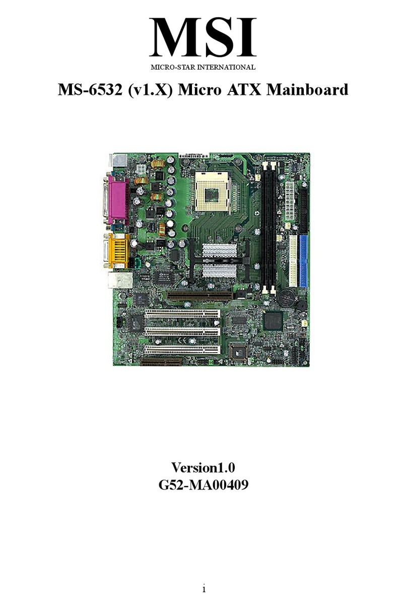
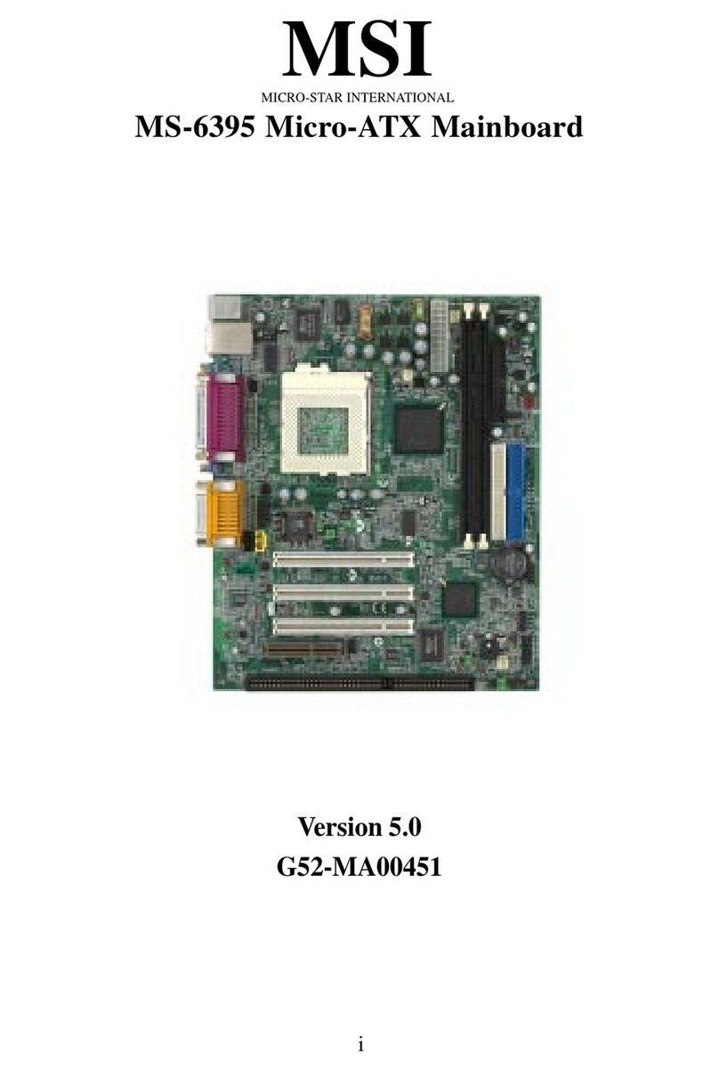
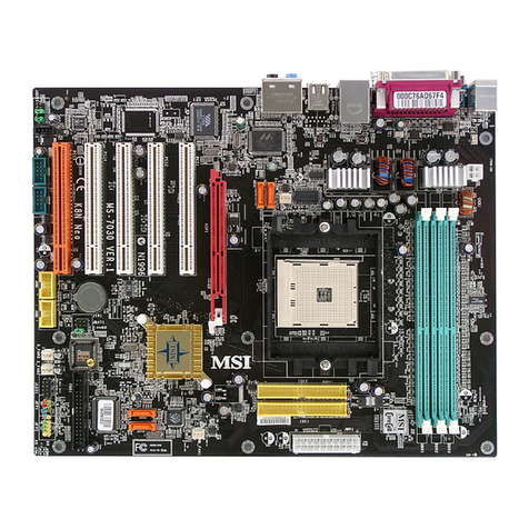
MSI MICRO ATX AL12 User manual

CHAPTER 1 INTRODUCTION
1-1
Chapter 1
INTRODUCTION
The MICRO ATX AL12 mainboard is a high-performance personal computer
mainboard. This mainboard supports Intel® Pentium® processor/Pentium®
processor with MMXTM technology,AMD® K5/K6/K6-2, and Cyrix® 6x86/
6x86L/6x86MX/MII processors. This mainboard combines leading edge
AGPATI®3D 128VR technology in graphics and Creative®ES1373PCI
Enhanced technology in audio. The mainboard also supports three 32-bit
PCI (Peripheral Component Interconnect) Local Bus standard slots.
The mainboard uses the highly integrated Aladdin® 5 chipset to support the
PCI/ISA and Green standards, and to provide the Host/AGP bridge. The
Aladdin® 5 chipset integrates all system control functions such as ACPI
(Advanced Configuration and Power Interface). The ACPI provides more
Energy Saving Features for the OSPM(OS Direct Power Management)
function. The Aladdin® 5 chipset also improves the IDE transfer rate by
supporting Ultra DMA/33 IDE that transfer data at the rate of 33MB/s.
The mainboard also supports the Hardware Monitor Controller as an
optional function. This function includes: CPU/chassis/power fan control,
CPU temperature detect and protect, and system voltage detect.

CHAPTER 1 INTRODUCTION
1-2
1.1 Mainboard Features
CPU
lSocket 7 supports Intel®Pentium®processor/Pentium®processor with
MMXTM technology.
lCyrix®6x86/6x86L/6x86MX/MIIaresupported.
lAMD®K6/K6-2/K6-3 processors are supported.
Chipset
lAladdin® 5M1541/M1543Cchipset.
FSB (Front Side Bus)
l100/95/83.3/75/66/60MHzclocksaresupported.
Cache Memory
lSupports 512K or 1MB Pipelined Burst cache memory.
Switching Regulator
lProvidesCPUwithvoltagerangingfrom1.3Vto3.5V
lSupport VI/O 3.45 for AMD K6 300 processor
Main Memory
lSupports four memory banks using two 168-pin unbuffered DIMM.
lSupportsamaximummemorysize of 256MB.
lSupports 3.3v Extended Data Output (EDO) and SDRAM DIMM.
Slots
lThree 32-bit Master PCI Bus slots and one 16-bit ISA bus slots. (wherein
one PCI/ISA is shared)
lSupports 3.3v/5v PCI bus Interface.
On-Board IDE
lAn IDE controller on the Aladdin®M1543C PCI Chipset provides IDE
HDD/CD-ROMwith PIO, DMA and Ultra DMA/33 operation modes.
lConnect up to four IDE devices.

CHAPTER 1 INTRODUCTION
1-3
Video
lATI®3D 128 VR
-Running on AGP BUS.
-Onboard8MB SDRAM.
- 3D Acceleration.
Audio
lCreative®ES1373
-Runningon PCI BUS.
-64VoiceandAC3Capable
- Support Direct Sound and Direct Sound 3D
-AC97’Compliant
On-Board Peripherals
lOn-BoardPeripherals include:
- 1 floppy port supports 2 FDD with 360K, 720K, 1.2M, 1.44M and
2.88Mbytes.
- 1 serial ports (COMA)
- 1 parallel port supports SPP/EPP/ECP mode
- 2 USB ports
-1 IrDA connector for SIR/FIR.
-1VGAport
BIOS
lThe mainboard BIOS provides “Plug & Play” BIOS which detects the
peripheral devices and expansion cards of the board automatically.
lThe mainboard provides a Desktop Management Interface(DMI) function
which records your mainboard specifications.
Dimension
lMicro-ATXformfactor: 24.4cm(L)x 24.5cm(W)x 4layersPCB
Mounting
l7 mounting holes.

CHAPTER 1 INTRODUCTION
1-4
Remote Control
lMeet ACPI specifications.
lPower ON/OFF switch connector on-board.
lSoftPower-Off.
lSupport modem ring wake-up .
lSupportalarmwake-up.
lSupport LAN wake-up.

CHAPTER 1 INTRODUCTION
1-5
1.2 Mainboard Layout
MS-5185 MICRO ATX AL12 Mainboard
Socket 7
DIMM
DIMM 2
FDD1
IDE 1
PCISlot
BIOS
IDE 2
PCISlot
PCISlot
ISA Slot
ATX
PowerSupply
Aladdin® 5
chipset
T:Mouse
B:
Keyboard
T:PrinterPort
B:SerialPort/
VGAPort
USB
Ports
Batt
DIMM 1
SW
PCUFAN
Socket 7
ATI® 3D
RAGE
PRO
Turbo
Creative
ES1371
JTAD1
JAUX1
CHSFAN
JFP1
Aladdin®
M1543C
chipset
SDRAM
Top: Midi/
GamePort
Bottom:
Line-In
Line-Out
Mic
SDRAM
SDRAM
SDRAM
JCD1
JSFAN
JV1 1
5
JSCL1
JCMOS

CHAPTER 2 HARDWARE INSTALLATION
2-1
CPU
CPU
Chapter 2
HARDWARE INSTALLATION
2.1 Central Processing Unit: CPU
The MICROATXAL12mainboard operates with Intel®Pentium®proces-
sor/Pentium® processor withMMXTM technology,AMD®K5/K6/K6-2,and
Cyrix®6x86/6x86L/6x86MX/MII processors. It could operate with 2.0V to
3.5V processors. The mainboard provides a 321-pin ZIF Socket 7 for easy
CPU installation, a DIP switch (SW1) to set the proper speed for the CPU
and (JV1) for setting the CPU voltage. It is recommended that the processor
should have a cooling fan attached to prevent from overheating.
3. Press the lever down to
complete the installation.
2. Locate Pin 1 in the socket
and look for the white dot or
cut edge in the CPU. Match
Pin 1 with the white dot/cut
edge. Then, insert the CPU.
It should insert easily.
OpenLever
Pin1
Sliding
Plate
White dot/
Cut edge
Close
Lever
1. Pull the lever sideways away
from the socket. Then, raise
the lever up to a 90-degree
angle.
2.1-1 CPU Installation Procedure

CHAPTER 2 HARDWARE INSTALLATION
2-2
2.1-2 CPU Core Speed Derivation Procedure
4 5 6 Clock
OFF OFF OFF 100MHz
ON OFF OFF 95MHz
OFF ON OFF 83MHz
OFF OFF ON 75MHz
OFF ON ON 66MHz
ON ON ON 60MHz
ON OFF ON 68MHz
SW1 CPU
1. The DIP Switch SW1 (4, 5, & 6) is used to adjust the CPU clock frequency.
2. The DIP Switch SW1 (1, 2, and 3) is used to set the Core/Bus (Fraction)
ratio of the CPU. The actual core speed of the CPU is the Host Clock
Frequency multiplied by the Core/Bus ratio. For example:
If CPUClock = 66MHz
Core/Busratio = 3/2
then CPUcore speed = Host Clock x Core/Bus ratio
= 66MHz x 3/2
= 100MHz
SW1 CPU
1 2 3 Core/Bus Ratio
OFF OFF ON 5.5x
OFF ON ON 5x
ON ON ON 4.5x
ON OFF ON 4x
OFF OFF OFF 3.5x
OFF ON OFF 3x
ON ON OFF 2.5x
ON OFF OFF 2x

CHAPTER 2 HARDWARE INSTALLATION
2-3
2.1-3 CPU Voltage Setting: JV1
JV1
1
2
3
4
5
Vcore
V I/O
3.4 3.4
3.4 3.3
3.4 3.2
3.4 2.9
JV1 VcoreV I/O
3.4 2.8
3.4 2.3
3.4 2.2
JV1
1
2
3
4
5
1
2
3
4
5
1
2
3
4
5
1
2
3
4
5
1
2
3
4
5
1
2
3
4
5
1
2
3
4
5

CHAPTER 2 HARDWARE INSTALLATION
2-4
1 2 3 4 5 VI/O VCore
OFF OFF OFF OFF ON 3.45 1.3
ON OFF OFF OFF ON 3.45 1.35
OFF ON OFF OFF ON 3.45 1.4
ON ON OFF OFF ON 3.45 1.45
OFF OFF ON OFF ON 3.45 1.5
ON OFF ON OFF ON 3.45 1.55
OFF ON ON OFF ON 3.45 1.6
ON ON ON OFF ON 3.45 1.65
OFF OFF OFF ON ON 3.45 1.7
ON OFF OFF ON ON 3.45 1.75
OFF ON OFF ON ON 3.45 1.8
ON ON OFF ON ON 3.45 1.85
OFF OFF ON ON ON 3.45 1.9
ON OFF ON ON ON 3.45 1.95
ON ON ON ON ON 3.45 2.0
ON OFF OFF OFF OFF 3.45 2.1
OFF ON OFF OFF OFF 3.45 2.2
ON ON OFF OFF OFF 3.45 2.3
OFF OFF ON OFF OFF 3.45 2.4
ON OFF ON OFF OFF 3.45 2.5
OFF ON ON OFF OFF 3.45 2.6
ON ON ON OFF OFF 3.45 2.7
OFF OFF OFF ON OFF 3.45 2.8
ON OFF OFF ON OFF 3.45 2.9
OFF ON OFF ON OFF 3.45 3.0
ON ON OFF ON OFF 3.45 3.1
OFF OFF ON ON OFF 3.45 3.2
ON OFF ON ON OFF 3.45 3.3
OFF ON ON ON OFF 3.45 3.4
ON ON ON ON OFF 3.45 3.5
Other CPU Voltage Setting

CHAPTER 2 HARDWARE INSTALLATION
2-5
To set the proper speed and voltage of the CPU, you must know the specifi-
cations of your CPU (always ask the vendor for CPU specifications).
Then refer to Table 2.1 (Intel®Processor), Table 2.2 (Cyrix®
Processor), and Table 2.3 (AMD®Processor) for proper setting.
2.1-3 CPU Speed and Voltage Setting: SW1 and JV1
SW1
JV1
1
2
3
4
5
ON
OFF
1234
ON
65

CHAPTER 2 HARDWARE INSTALLATION
2-6
Table 2.1 Intel®Processor
90 MHz
100 MHz
120 MHz
133 MHz
3.38
3.52
CPU
Type CPU SpeedCPU Voltage
VI/O Vcore
166 MHz
200 MHz 3.3 2.8
233 MHz
b. Intel®Pentium® Processorwith MMXTM Technology
a. Intel®Pentium® Processor
Note: In case, you encounter a CPU with different voltage, just go to
Section 2.1-3 and look for the proper voltage settings.
SW1JV1
150 MHz
166 MHz
180 MHz
200 MHz
ON
OFF
1234
ON
65
ON
OFF
1234
ON
65
ON
OFF
1234
ON
65
ON
OFF
1234
ON
65
ON
OFF
1234
ON
65
ON
OFF
1234
ON
65
ON
OFF
1234
ON
65
ON
OFF
1234
ON
65
ON
OFF
1234
ON
65
ON
OFF
1234
ON
65
ON
OFF
1234
ON
65
1
2
3
4
5
1
2
3
4
5

CHAPTER 2 HARDWARE INSTALLATION
2-7
Table 2.2 Cyrix®Processor
Cyrix®6x86 processor uses PR to rate the speed of their processors based
on Intel®Pentium®processor core speed. For example, PR150 (120MHz)
has 150MHz core speed of Intel® Pentium®processor, but it has120MHz
core speed in Cyrix® processor. Cyrix®6x86 processor should always use a
more powerful fan (ask vendor for proper cooling fan).
CPU
Type
CPU SpeedCPU Voltage
VI/O Vcore
PR166
133MHz (66x2)
3.5
a. Cyrix®6x86 processor
JV1 SW1
PR150
120MHz (60x2)
PR200
166MHz(66x2.5)
CPU
Type
CPU Voltage
VI/O Vcore
PR166
133MHz (66x2)
2.8
b. Cyrix®6x86L processor
JV1
PR150
120MHz (60x2)
PR200
166MHz(66x2.5)
3.4
ON
OFF
1234
ON
65
ON
OFF
1234
ON
65
ON
OFF
1234
ON
65
ON
OFF
1234
ON
65
ON
OFF
1234
ON
65
ON
OFF
1234
ON
65
1
2
3
4
5
1
2
3
4
5
SW1
CPU Speed

CHAPTER 2 HARDWARE INSTALLATION
2-8
CPU
Type
CPU Speed
CPU Voltage
VI/O Vcore
PR233
(66 x 3)
3.4 2.9
PR200
(75 x 2)
PR266
(83 x 2.5)
c. Cyrix®6x86MX Processor
(75 x 2.5)
SW1
JV1
(83 x 2)
CPU
Type
CPU SpeedCPU Voltage
VI/O Vcore
PR300
(66x3.5) 2.9
d. Cyrix®MII processor
JV1 SW1
PR333
(100x2.5)
3.4
Note: In case, you encounter a CPU with different voltage, just go to
Section 2.1-3 and look for the proper voltage settings.
1
2
3
4
5
1
2
3
4
5
ON
OFF
1234
ON
65
ON
OFF
1234
ON
65
ON
OFF
1234
ON
65
ON
OFF
1234
ON
65
ON
OFF
1234
ON
65
ON
OFF
1234
ON
65
ON
OFF
1234
ON
65

CHAPTER 2 HARDWARE INSTALLATION
2-9
Table 2.3 AMD®Processor
AMD®K5/K6 processor uses PR to rate the speed of their processors based
on Intel®Pentium® processor core speed . For example, PR133(100MHz)
has 133MHz core speed of Intel® Pentium® processor but has 100MHz core
speed in AMD®processor.
3.52
CPU
Type
CPU SpeedCPU Voltage
VI/O Vcore
PR133
SW1
a. AMD®K5 Processor
PR150
JV1
PR166
ON
OFF
1234
ON
65
ON
OFF
1234
ON
65
ON
OFF
1234
ON
65
1
2
3
4
5

CHAPTER 2 HARDWARE INSTALLATION
2-10
3.4
200MHz
233MHz
166MHz 2.9
b. AMD®K6 Processor
3.4 3.2
2.2
266MHz
300MHz
K6-2 300MHz
CPU
Type
CPU SpeedCPU Voltage
VI/O Vcore SW1
JV1
K6-2 333MHz
K6-2 350MHz
3.4
Note: In case, you encounter a CPU with different voltage, just go to
Section 2.1-3 and look for the proper voltage settings.
K6-2366MHz
K6-2380MHz
K6-2400MHz
ON
OFF
1234
ON
65
ON
OFF
1234
ON
65
ON
OFF
1234
ON
65
ON
OFF
1234
ON
65
ON
OFF
1234
ON
65
ON
OFF
1234
ON
65
ON
OFF
1234
ON
65
ON
OFF
1234
ON
65
ON
OFF
1234
ON
65
ON
OFF
1234
ON
65
ON
OFF
1234
ON
65
1
2
3
4
5
1
2
3
4
5
1
2
3
4
5

CHAPTER 2 HARDWARE INSTALLATION
2-11
2.1-6 Fan Power Connectors: CPUFAN, PSFAN & CHSFAN
These connectors support system cooling fan with +12V. It supports three
pin head connector. When connecting the wire to the connector, always
take note that the red wire is the positive and should be connected to the
+12V, the black wire is Ground and should be connected to GND. If your
mainboard has System Hardware Monitor chipset on-board, you can use a
specially designed fan w/ speed sensor to take advantage of System Hard-
ware Monitor’s CPU fan control.
Note: Always consult vendor for proper CPU cooling fan.
For fans with fan speed sensor, every rotation of the fan will send out 2
pulses. System Hardware Monitor will count and report the fan rotation
speed.
CHSFAN
+12V
SPEED
GND
JFAN1: CPU FAN
JSFAN1: System (chassis) FAN
JPFAN1: Power FAN
CPUFAN
+12V
SPEED GND
PSFAN
+12V
SPEED GND

CHAPTER 2 HARDWARE INSTALLATION
2-12
2.2 Memory Installation
2.2-1 Memory Bank Configuration
The mainboard provides two 168-pin DIMM (Double In-Line Memory) sock-
ets. It supports four memory banks for a maximum of 512MB memory.
You can use DIMM from 8MB, 16MB, 32MB, 64MB, 128MB to 256MB.
DIMM1(Bank1/2)
DIMM2(Bank3/4)
If you use 100 MHz CPU Bus Frequency, only PC100
DIMM Specs. is supported.
!
WARNING!

CHAPTER 2 HARDWARE INSTALLATION
2-13
A. How to install DIMM Module
1. The DIMM slot has two keys marked “VOLT and DRAM” , so
the DIMM memory module can only fit in one direction.
2. Insert the DIMM memory module vertically into the DIMM slot.
Then, push it in.
3. The plastic clip at the side of the DIMM slot will automatically
close.
SingleSidedDIMM
DoubleSidedDIMM
DRAM VOLT
2.2-2 Memory Installation Procedure:

CHAPTER 2 HARDWARE INSTALLATION
2-14
2.2-3 Memory Population Rules
1. This mainboard supports Table Free memory, so memory can be in-
stalled in DIMM1 or DIMM2 in any order.
2. Use only 3.3v unbuffered DIMM.
3. The DRAM addressing and the size supported by the mainboard is
shown next page.
4. Using 100MHz CPU Bus frequency, only PC100 DIMM is supported.

CHAPTER 2 HARDWARE INSTALLATION
2-15
16M 1Mx16 ASYM 11 8 8MBx4 16MBx8
2Mx8 ASYM 11 9 16MBx8 32MBx16
4Mx4 ASYM 11 10 32MB 64MB
64M 2Mx32 ASYM 11 9 32MBx2 64MBx4
2Mx32 ASYM 12 8 16MBx2 32MBx4
4Mx16 ASYM 11 10 32MB 64MB
4Mx16 ASYM 13 8 32MB 64MB
8Mx8 ASYM 13 9 64MB 128MB
16Mx4 ASYM 13 10 128MB 256MB
64M 2Mx32 ASYM 11 8
4Mx16 ASYM 12 8
8Mx8 ASYM 12 9
16Mx4 ASYM 12 10
DRAM
Tech.
DRAM
Density &
Width
DRAM
Addressing Address Size MB/DIMM
Row Column Single
Side(S) Double
Side(D)
Table 2.2-1 EDO DRAM Memory Addressing
no.
pcs. no.
pcs.
Table 2.2-2 SDRAM Memory Addressing
16M 1Mx16 SYMM 10 10 8MBx4 16MBx8
1Mx16 ASYM 12 8 8MBx4 16MBx8
2Mx8 ASYM 11 10 16MBx8 32MBx16
2Mx8 ASYM 12 9 16MBx8 32MBx16
4Mx4 SYMM 11 11 32MBx16 64MBx32
4Mx4 ASYM 12 10 32MBx16 64MBx32
64M 2Mx32 ASYM 11 10 16MBx2 32MBx4
2Mx32 ASYM 12 9 16MBx2 32MBx4
2Mx32 ASYM 13 8 16MBx2 32MBx4
4Mx16 SYMM 11 11 32MBx4 64MBx8
4Mx16 ASYM 12 10 32MBx4 64MBx8
8Mx8 ASYM 12 11 64MBx8128MBx16
DRAM
Tech.
DRAM
Density &
Width
DRAM
Addressing Address Size MB/DIMM
Row Column Single
Side(S) Double
Side(D)
no.
pcs. no.
pcs.
Table of contents
Other MSI Motherboard manuals

MSI
MSI X48 Platinum Series User manual

MSI
MSI MS-6567 User manual

MSI
MSI RX480 Neo2 MS-7151 User manual

MSI
MSI FUZION Series User manual

MSI
MSI A88XI AC User manual

MSI
MSI X99A RAIDER User manual

MSI
MSI Z390-A PRO User manual

MSI
MSI B75MA-E2 User manual

MSI
MSI PM8M2-V Series User manual

MSI
MSI MS-7329 User manual

MSI
MSI Z790-S01 User manual

MSI
MSI MS-7174 User manual

MSI
MSI FUZZY CX700 User manual

MSI
MSI MS-7255 User manual

MSI
MSI MS-9802 User manual

MSI
MSI MPG B550 GAMING CARBON WIFI User manual

MSI
MSI H97M ECO User manual

MSI
MSI MAG B660M MORTAR WIFI DDR4 User manual

MSI
MSI MICRO ATX ZX14 User manual

MSI
MSI MEG Z590 UNIFY-X User manual