MSI MPG X670E CARBON WIFI User manual

MPG X670E CARBON WIFI
Motherboard
User Guide
Benutzerhandbuch
Manuel d’utilisation
Руководство пользователя
取扱説明書
사용 명서
使用手冊
使用手册

1
Contents
Quick Start..................................................................................................................... 3
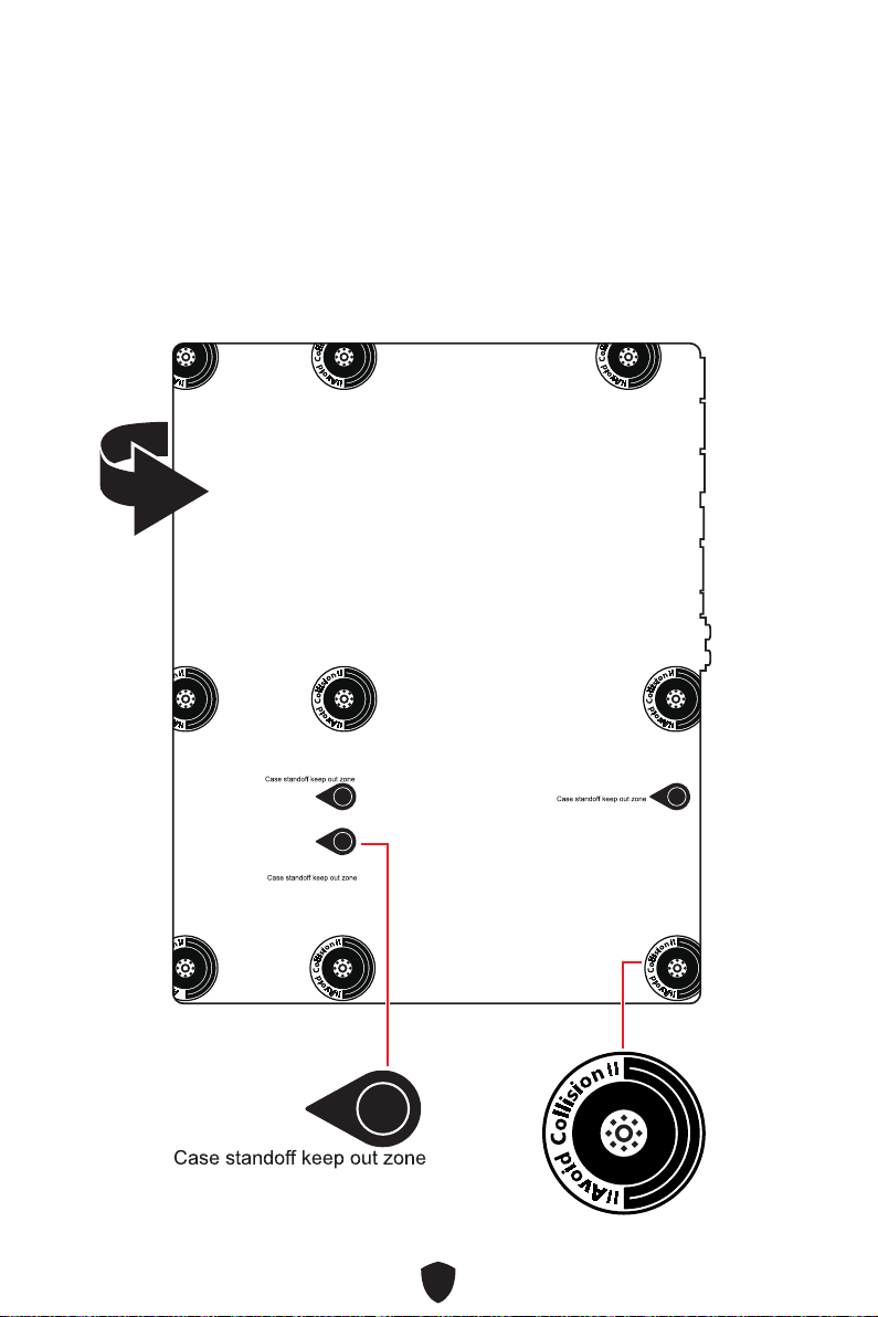
Case stand-off notification ..................................................................................... 5
Avoid collision notification...................................................................................... 5
Specifications.............................................................................................................. 16
Special Features......................................................................................................... 20
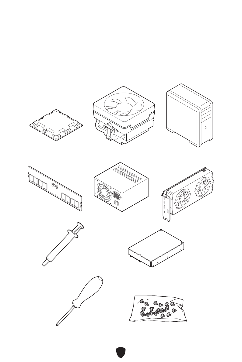
Package Contents ...................................................................................................... 21
Back Panel Connectors ............................................................................................. 22
LAN Port LED Status Table .................................................................................. 24
Audio Jacks Connection ....................................................................................... 24
Installing Antennas............................................................................................... 26
Overview of Components........................................................................................... 27
CPU Socket ........................................................................................................... 28
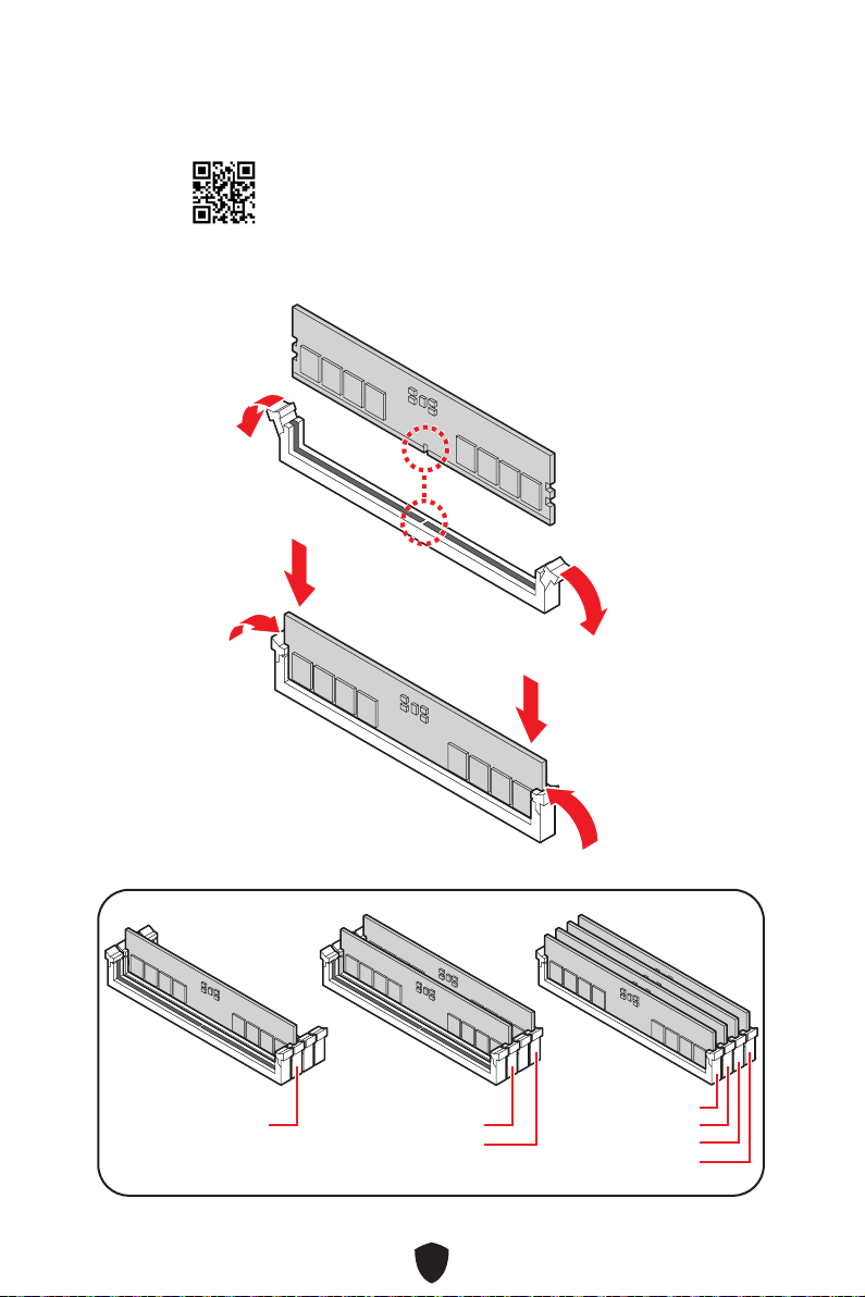
DIMM Slots............................................................................................................ 29
PCI_E1~3: PCIe Expansion Slots.......................................................................... 30
SATA_P1~2, SATA_P3~4 & SATA_S3~4: SATA 6Gb/s Connectors ...................... 31
M2_1~4: M.2 Slots (Key M) ................................................................................... 32
JAUD1: Front Audio Connector ............................................................................ 40
JFP1, JFP2: Front Panel Connectors................................................................... 40
CPU_PWR1~2, ATX_PWR1: Power Connectors................................................... 41
JCI1: Chassis Intrusion Connector....................................................................... 42
JUSB1: USB 3.2 Gen 2 Type-C Front Panel Connector ....................................... 43
JUSB2~3: USB 3.2 Gen 1 Connectors .................................................................. 43
JUSB4~5: USB 2.0 Connectors............................................................................. 44
JOC_FS1: Safe Boot Jumper................................................................................ 44
T_SEN1: Thermal Sensor Connector................................................................... 45
JDASH1 : Tuning Controller Connector ............................................................... 45
CPU_FAN1
, PUMP_FAN1, SYS_FAN1~5
: Fan Connectors................................... 46
JBAT1: Clear CMOS (Reset BIOS) Jumper........................................................... 47
BAT1: CMOS Battery............................................................................................. 48
JRGB1: RGB LED Connector ................................................................................ 49
JARGB_V2_1~2: A-RAINBOW V2 (ARGB Gen2) LED Connectors ........................ 50
English

2
Onboard LEDs............................................................................................................. 52
EZ Debug LED....................................................................................................... 52
LED_SW1: EZ LED Control................................................................................... 52
JPWRLED1: LED power input............................................................................... 52
Debug Code LED................................................................................................... 53
Boot Phases.......................................................................................................... 53
Debug Code LED Table......................................................................................... 53
Installing OS, Drivers & MSI Center.......................................................................... 58
MSI Center............................................................................................................ 61
UEFI BIOS.................................................................................................................... 62
BIOS Setup............................................................................................................ 63
Resetting BIOS...................................................................................................... 64
Updating BIOS....................................................................................................... 64

3
Quick Start
Thank you for purchasing a new motherboard from MSI®. This Quick Start section
provides demonstration diagrams about how to install your computer. Some of the
installations also provide video demonstrations. Please link to the URL to watch it
with the web browser on your phone or tablet. You may have even link to the URL by
scanning the QR code.
Preparing Tools and Components
AMD AM5 CPU AM5 CPU Fan
DDR5 Memory
Graphics Card
SATA Hard Disk Drive
Phillips Screwdriver
Chassis
Power Supply Unit
A Package of Screws
Thermal Paste

4
Safety Information
∙The components included in this package are prone to damage from electrostatic
discharge (ESD). Please adhere to the following instructions to ensure successful
computer assembly.
∙Ensure that all components are securely connected. Loose connections may cause
the computer to not recognize a component or fail to start.
∙Hold the motherboard by the edges to avoid touching sensitive components.
∙It is recommended to wear an electrostatic discharge (ESD) wrist strap when
handling the motherboard to prevent electrostatic damage. If an ESD wrist strap
is not available, discharge yourself of static electricity by touching another metal
object before handling the motherboard.
∙Store the motherboard in an electrostatic shielding container or on an anti-static
pad whenever the motherboard is not installed.
∙Before turning on the computer, ensure that there are no loose screws or metal
components on the motherboard or anywhere within the computer case.
∙Do not boot the computer before installation is completed. This could cause
permanent damage to the components as well as injury to the user.
∙If you need help during any installation step, please consult a certified computer
technician.
∙Always turn off the power supply and unplug the power cord from the power outlet
before installing or removing any computer component.
∙Keep this user guide for future reference.
∙Keep this motherboard away from humidity.
∙Make sure that your electrical outlet provides the same voltage as is indicated on
the PSU, before connecting the PSU to the electrical outlet.
∙Place the power cord such a way that people can not step on it. Do not place
anything over the power cord.
∙All cautions and warnings on the motherboard should be noted.
∙If any of the following situations arises, get the motherboard checked by service
personnel:
• Liquid has penetrated into the computer.
• The motherboard has been exposed to moisture.
• The motherboard does not work well or you can not get it work according to user
guide.
• The motherboard has been dropped and damaged.
• The motherboard has obvious sign of breakage.
∙Do not leave this motherboard in an environment above 60°C (140°F), it may damage
the motherboard.

5
Case stand-off notification
To prevent damage to the motherboard, any unnecessary mounting stand-off between
the motherboard circuits and the computer case is prohibited. The Case standoff keep
out zone signs will be marked on the backside of motherboard (as shown below) to
serve as a warning to user.
Avoid collision notification
Protective paint is printed around each screw hole to prevent parts from being
scratched.

6
Installing a Processor
11
22
33
6644
55
77
88
1111
99
1010
⚽
∙https://youtu.be/cltgIYiGtWY

7
⚠
Important
If you are installing the screw-type CPU heatsink, please follow the figure below to
remove the retention module first and then install the heatsink.

8
Installing DDR5 memory
∙https://youtu.be/XiNmkDNZcZk
⚽
DIMMA2 DIMMA2
DIMMB2
DIMMA1
DIMMA2
DIMMB1
DIMMB2

9
HDD LED
RESET SW
Connecting the Front Panel Header
∙http://youtu.be/DPELIdVNZUI
JFP1
HDD LED HDD LED -
HDD LED +
POWER LED -
POWER LED +
POWER LED
RESET SW
POWER SW
POWER LED+
POWER LED-
HDD LED
⚽
1
2 10
9
Power LED
Reserved
Power Switch
JFP1
Reset SwitchHDD LED

10
Installing the Motherboard
∙https://youtu.be/wWI6Qt51Wnc
⚽
BAT1
11
Torque:
3 kgf·cm*
*3 kgf·cm
= 0.3 N·m
= 2.6 lbf·in
22

11
Connecting the Power Connectors
∙http://youtu.be/gkDYyR_83I4
ATX_PWR1
CPU_PWR1~2
⚽

12
Installing SATA Drives
∙http://youtu.be/RZsMpqxythc
11
2233
44
55
⚽

13
Installing a Graphics Card
∙http://youtu.be/mG0GZpr9w_A
⚽
11
22
33
44
55
66

14
Connecting Peripheral Devices
Processor with integrated graphics

15
Power On
44
33
1122

16
Specifications
CPU
∙Supports AMD Ryzen™ 7000 Series Desktop Processor*
∙Supports Processor socket AM5
* Please go to www.msi.com to get the newest support status as new processors
are released.
Chipset AMD X670 Chipset
Memory
∙4x DDR5 memory slots, supporting up to 128GB*
∙Supports 1R 4800 MHz by JEDEC
∙Max overclocking frequency:
• 1DPC 1R Max. speed up to 6600+ MHz
• 1DPC 2R Max. speed up to 6000+ MHz
• 2DPC 1R Max. speed up to 6400+ MHz
• 2DPC 2R Max. speed up to 4000+ MHz
∙Supports Dual-Channel mode
∙Supports non-ECC, un-buffered memory
∙Supports AMD EXPO
* Please refer to www.msi.com for more information on compatible memory.
Expansion Slots
∙3x PCIe x16 slots
• Supports x16/x0/x4, x8/x8/x4
• PCI_E1 & PCI_E2 slots (From CPU)
• PCI_E1 supports up to PCIe 5.0 x16
• PCI_E2 supports up to PCIe 5.0 x8
• PCI_E3 slot (From X670 Chipset)
• Supports up to PCIe 4.0 x4
Onboard Graphics
∙1x HDMI™ 2.1 port with FRL, supporting a maximum
resolution of 4K 120Hz*/ **
∙1x DisplayPort 1.4 port, supporting a maximum resolution
of 4K 60Hz*/ **
∙1x DisplayPort 1.4 over USB-C port with HBR3, supporting
a maximum resolution of 4K 120Hz*/**
* Available only on processors featuring integrated graphics.
** Graphics specifications may vary depending on the CPU installed.
Multi-GPU Supports AMD Multi-GPU
SATA Ports 6x SATA 6Gb/s ports (From X670 Chipset)
Continued on next column

17
Continued from previous column
M.2 SSD Slots
∙4x M.2 slots (Key M)
• M2_1 & M2_2 slots (From CPU)
• Supports up to PCIe 5.0 x4
• Supports 2260/ 2280 storage devices
• M2_3 & M2_4 slots (From X670 chipset)
• Supports up to PCIe 4.0 x4
• M2_3 supports 2260/ 2280/ 22110 storage devices
• M2_4 supports 2260/ 2280 storage devices
RAID
∙Supports RAID 0, RAID 1 and RAID 10 for SATA storage
devices
∙Supports RAID 0, RAID 1 and RAID 10 for M.2 NVMe
storage devices
Audio
Realtek® ALC4080 Codec
∙7.1-Channel USB High Performance Audio
∙Supports up to 32-bit/384kHz playback on front panel
∙Supports S/PDIF output
LAN ∙1x Realtek® RTL8125 2.5Gbps LAN controller
Wi-Fi & Bluetooth®
AMD Wi-Fi 6E
∙The Wireless module is pre-installed in the M.2 (Key-E)
slot
∙Supports MU-MIMO TX/RX
∙Supports 20MHz, 40MHz, 80MHz,160MHz bandwidth in
2.4GHz/ 5GHz or 6GHz* bands
∙Supports 802.11 a/ b/ g/ n/ ac/ ax
∙Supports Bluetooth® 5.2**
* Wi-Fi 6E 6GHz may depend on every country’s regulations and will be ready in
Windows 10 build 21H1 and Windows 11.
** Bluetooth 5.2 will be ready in Windows 10 build 21H1 and Windows 11.
Power Connectors ∙1x 24-pin ATX main power connector
∙2x 8-pin +12V power connectors
Continued on next column

18
Continued from previous column
Internal USB
Connectors
∙1x USB 3.2 Gen 2 10Gbps Type-C front panel connector
(From X670 chipset)
∙2x USB 3.2 Gen 1 5Gbps connectors (From X670 chipset)
• Supports additional 4 USB 3.2 Gen 1 5Gbps ports
∙2x USB 2.0 Type-A connectors (From X670 chipset)
• Supports additional 4 USB 2.0 ports
Fan Connectors
∙1x 4-pin CPU fan connector
∙1x 4-pin water-pump fan connector
∙5x 4-pin system fan connectors
System Connectors
∙1x Front panel audio connector
∙2x System panel connectors
∙1x Chassis intrusion connector
∙1x 2-pin Thermal sensor connector
∙1x Tuning controller connector
Switch ∙1x EZ LED Control switch
Jumpers ∙1x Clear CMOS jumper
∙1x OC safe boot jumper
LED Features
∙1x 4-pin RGB LED connector
∙2x 3-pin A-RAINBOW V2 (ARGB Gen2) LED connectors
∙4x EZ Debug LED
∙1x LED Demo connector
∙1x 2-Digit Debug Code LED
Continued on next column
Other manuals for MPG X670E CARBON WIFI
1
Table of contents
Other MSI Motherboard manuals

MSI
MSI 785GT-E63 Series User manual

MSI
MSI PRO H610M-G DDR4 User manual

MSI
MSI B660-A PRO DDR4 User manual

MSI
MSI H170A PC MATE User manual

MSI
MSI G41M-P34 User manual

MSI
MSI MS-6137 User manual

MSI
MSI MS-98H6 User manual

MSI
MSI ms-7377 User manual

MSI
MSI MAG B660 TOMAHAWK WIFI User manual

MSI
MSI MS-6135 User manual

MSI
MSI PRO B660M-A CEC WIFI User manual

MSI
MSI MEG X570S ACE MAX User manual

MSI
MSI B75MA-E31 Sereis User manual

MSI
MSI MS-7003 User manual

MSI
MSI B550M PRO-DASH User manual

MSI
MSI H57M-ED65 Series User manual

MSI
MSI 760GA-P43 FX User manual

MSI
MSI 865GVM3-V - Motherboard - Micro ATX User manual

MSI
MSI 7B28-002R User manual

MSI
MSI 611BF User manual