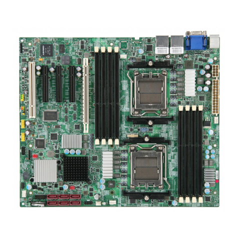
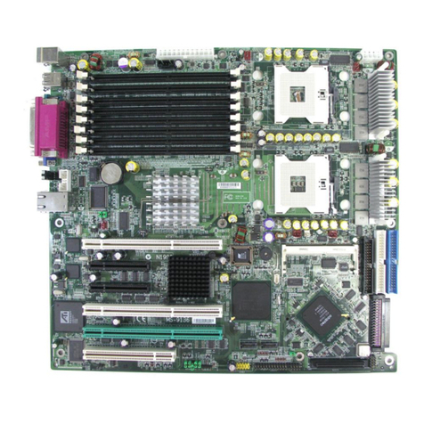
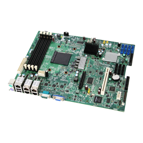
MSI MS-S2381 User manual

i
MS-S2381
Server Board

ii
Preface MS-S2381
Copyright and Trademarks Notice
Copyright © Micro-Star Int’l Co., Ltd. All rights reserved. The MSI logo used is a
registered trademark of Micro-Star Int’l Co., Ltd. All other marks and names men-
tioned may be trademarks of their respective owners. No warranty as to accuracy
or completeness is expressed or implied. MSI reserves the right to make changes
to this document without prior notice.
Revision History
Revision Date
V1.0 2021/08
Technical Support
If a problem arises with your product and no solution can be obtained from the
user’s manual, please contact your place of purchase or local distributor. Alterna-
tively, please visit https://www.msi.com/support/ for further guidance.

iii
Preface MS-S2381
Safety Instructions
■Always read the safety instructions carefully.
■Keep this User’s Manual for future reference.
■Keep this equipment away from humidity.
■Lay this equipment on a reliable at surface before setting it up.
■The openings on the enclosure are for air convection hence protects the
equipment from overheating. DO NOT COVER THE OPENINGS.
■Make sure the voltage of the power source and adjust properly before con-
necting the equipment to the power inlet.
■Place the power cord such a way that people can not step on it. Do not place
anything over the power cord.
■Always Unplug the Power Cord before inserting any add-on card or module.
■All cautions and warnings on the equipment should be noted.
■Never pour any liquid into the opening that could damage or cause electrical
shock.
■If any of the following situations arises, get the equipment checked by ser-
vice personnel:
◯The power cord or plug is damaged.
◯Liquid has penetrated into the equipment.
◯The equipment has been exposed to moisture.
◯The equipment does not work well or you can not get it work according
to User’s Manual.
◯The equipment has dropped and damaged.
◯The equipment has obvious sign of breakage.
■DO NOT LEAVE THIS EQUIPMENT IN AN ENVIRONMENT UNCONDI-
TIONED, STORAGE TEMPERATURE ABOVE 60oC (140oF), IT MAY DAM-
AGE THE EQUIPMENT.

iv
Preface MS-S2381
Chemical Substances Information
In compliance with chemical substances regulations, such as the EU REACH
Regulation (Regulation EC No. 1907/2006 of the European Parliament and the
Council), MSI provides the information of chemical substances in products at:
https://storage-asset.msi.com/html/popup/csr/evmtprtt_pcm.html
Battery Information
European Union:
Batteries, battery packs, and accumulators should not be
disposed of as unsorted household waste. Please use the
public collection system to return, recycle, or treat them in
compliance with the local regulations.
廢電池請回收
Taiwan:
For better environmental protection, waste batteries should
be collected separately for recycling or special disposal.
California, USA:
The button cell battery may contain perchlorate material
and requires special handling when recycled or disposed
of in California.
For further information please visit:
https://dtsc.ca.gov/perchlorate/
Danger of explosion if battery is incorrectly replaced. Replace only with the
same or equivalent type recommended by the manufacturer.

v
Preface MS-S2381
CE Conformity
Hereby, Micro-Star International CO., LTD declares that this de-
vice is in compliance with the essential safety requirements and
other relevant provisions set out in the European Directive.
FCC-A Radio Frequency
Interference Statement
This equipment has been tested and found to comply with the limits
for a Class A digital device, pursuant to Part 15 of the FCC Rules.
These limits are designed to provide reasonable protection against
harmful interference when the equipment is operated in a commercial
environment. This equipment generates, uses and can radiate radio
frequency energy and, if not installed and used in accordance with
the instruction manual, may cause harmful interference to radio communications.
Operation of this equipment in a residential area is likely to cause harmful inter-
ference, in which case the user will be required to correct the interference at his
own expense.
Notice 1
The changes or modications not expressly approved by the party responsible for
compliance could void the user’s authority to operate the equipment.
Notice 2
Shielded interface cables and AC power cord, if any, must be used in order to
comply with the emission limits.
This device complies with Part 15 of the FCC Rules. Operation is subject to the
following two conditions:
1) this device may not cause harmful interference, and
2) this device must accept any interference received, including interference that
may cause undesired operation.
WEEE Statement
Under the European Union (“EU”) Directive on Waste Electrical and
Electronic Equipment, Directive 2012/19/EU, products of “electrical
and electronic equipment” cannot be discarded as municipal waste
anymore and manufacturers of covered electronic equipment will be
obligated to take back such products at the end of their useful life.
vi
Preface MS-S2381
CONTENTS
Copyright and Trademarks Notice................................................................. ii
Revision History ............................................................................................ ii
Technical Support.......................................................................................... ii
Safety Instructions.........................................................................................iii
Chemical Substances Information ............................................................... iv
Battery Information....................................................................................... iv
CE Conformity............................................................................................... v
FCC-A Radio Frequency Interference Statement ......................................... v
WEEE Statement .......................................................................................... v
1. Overview.......................................................................................1-1
Specications.............................................................................................1-2
Layout ........................................................................................................1-3
2. Hardware Setup ...........................................................................2-1
CPU Installation .........................................................................................2-3
Memory ......................................................................................................2-5
Storage.......................................................................................................2-9
Power Connectors....................................................................................2-10
Rear Panel I/O .........................................................................................2-12
Connectors...............................................................................................2-14
Jumper .....................................................................................................2-21
Slots .........................................................................................................2-22

1-1-1
Thank you for choosing the MS-S2381, an excellent server board from
MSI.
The MS-S2381 features the latest AMD® EPYC™ processor and the
industry’s latest technologies to deliver high-performance, feature-rich
server solutions for a wide array of business applications.
1Overview

1-2
Overview MS-S2381
Specications
Model S2381
Formfactor ATX
Dimensions 12”(W)x9.6"(D)
Processor 1xAMDEPYCRome/Milan(SocketSP3),upto64C,upto300W
Memory 8xDDR42400/2666/3200MHz,RDIMM/LRDIMMslots,w/ECC
Network 1xGbERJ45Mgmt(RealtekRTL8211E‐VBPHY)
2x10GbERJ45(IntelX710AT2)(1xw/NCSI)
Expansionslot 4xPCIe4.0x16slots
3xPCIe4.0x8slots
Storage
3xSlimlineSAS(12xSATA6Gb/s)
2xSlimlineSAS(PCIe4.0x4)forU.2
2xM.2M‐Key2280/22110(PCIe4.0x4)
InternalI/O
1xVGAheader
1xCOMheader
2xUSB3.2/2.0(header)
1xFrontPanelheader
1xChassisintrusionheader
1xIPMBheader
1xPWRSMBheader
1x24pinpowerconnector
1x8pinpowerconnector
1x4pinpowerconnector
RearI/O
4xUSB3.2/2.0
2x10GBase‐T
1xRJ45Mgmt.
1xVGAPort
1xCOMPortDB9
1xUIDw/LED
Security TPM2.0headeronboard
Management AspeedAST2500IPMI2.0withiKVMsupport(dualBMCdesign)
Environment
OperatingTemperature:0°Cto35°C(aircooler),supportCPUupto240W
0°Cto40°C(liquidcooling),supportCPUupto300W
Non‐operatingTemperature:‐5°Cto70°C
Non‐operatingRelativeHumidity:5%to85%(non‐condensing)
Cooling
CPUaircooler,liquidcoolingisoptional
6xFANheadersforsystemFANs
1xFANheaderforCPUcooler
Powersupply ATXPower
Certification CE,FCC(ClassA)

1-3
Overview MS-S2381
Layout
JPWR1
JPWR2
JPWR3
JPMBUS1
PCIE_SLOT6
PCIE_SLOT7
PCIE_SLOT5
PCIE_SLOT4
PCIE_SLOT3
PCIE_SLOT2
PCIE_SLOT1
JSL_SATA2
JSL_SATA3
JSL_SATA1
SYS_FAN1
SYS_FAN2
SYS_FAN5
SYS_FAN4
SYS_FAN3
JCOM3
JFUSB1
JCOM2JVGA1
JFP1 JTPM1 JSGPIO1
JIPMB1
NVME_SW
BIOS_SW1
JFPGA1
JCHASSIS1
M2_1
M2_2
JSPI1
CPU_FAN1
SYS_FAN6
SOC_SMB
JNVME1_2
JNVME1_1
BP_I2C_1
RTC_CLR2_1
JRESET1
M7
M6
M5
M4
M0
M1
M2
M3


2-2-1
This chapter provides you with the information about hardware
setup procedures. While doing the installation, be careful in holding
the components and follow the installation procedures. For some
components, if you install in the wrong orientation, the components will
not work properly.
Use a grounded wrist strap before handling computer components. Static
electricity may damage the components.
2Hardware Setup

2-2
Hardware Setup MS-S2381
Components Reference Guide
CPU Installation................................................................................2-3
Memory..............................................................................................2-5
Supported DIMM Congurations................................................................2-5
Memory Speed Based on DIMM Population..............................................2-7
Installing Memory Modules ........................................................................2-8
Storage ..............................................................................................2-9
Storage Support & Speed ..........................................................................2-9
Power Connectors..........................................................................2-10
Power Connectors: JPWR1, JPWR2, JPWR3 ........................................2-10
Rear Panel I/O .................................................................................2-12
Connectors......................................................................................2-14
CPU Fan Power Connectors: CPU_FAN1 ...............................................2-14
System Fan Power Connectors: SYS_FAN1 ~ SYS_FAN6.....................2-14
Front Panel Header: JFP1 .......................................................................2-15
Chassis Intrusion Header: JCHASSIS1 ...................................................2-16
VGA Box Header: JVGA1 ........................................................................2-16
PMBus Box Header: JPMBUS1...............................................................2-17
IPMB Box Header: JIPMB1......................................................................2-17
BP SMB Box Header: BP_I2C_1 .............................................................2-17
SOC SMB Box Header: SOC_SMB.........................................................2-17
COM Port Header: JCOM2 ......................................................................2-18
SGPIO Box Header: JSGPIO1.................................................................2-18
USB 3.2 Gen 1 Box Header: JFUSB1......................................................2-19
TPM Module Box Header: JTPM1 ...........................................................2-20
Jumper.............................................................................................2-21
Slots.................................................................................................2-22
PCIe (Peripheral Component Interconnect Express) Slot........................2-22

2-3
Hardware Setup MS-S2381
CPU Installation
19
12
35
6
4
7
8
9
10
13
11
12
14
15
16
18
17

2-4
Hardware Setup MS-S2381
Important
• Do not touch the CPU socket pins to avoid damage.
• Whenever CPU is not installed, always protect your CPU socket pins with the
plastic cap covered.
• Please refer to the documentation in the CPU cooler package for more details
about the CPU cooler installation.
• Read the CPU status in BIOS.

2-5
Hardware Setup MS-S2381
Memory
M7
M6
M5
M4
M0
M1
M2
M3
Channel H
Channel G
Channel F
Channel E
Channel A
Channel B
Channel C
Channel D
Supported DIMM Congurations

2-6
Hardware Setup MS-S2381

2-7
Hardware Setup MS-S2381
Memory Speed Based on DIMM Population

2-8
Hardware Setup MS-S2381
Installing Memory Modules
1. Unlock the DIMM slot by ipping open its side clips.
2. Vertically insert the DIMM into the DIMM slot. The DIMM has an o-center
notch at the bottom that will only allow it to t one way into the DIMM slot.
3. Push the DIMM deeply into the DIMM slot. The side clips of the slot will
automatically close when the DIMM is properly seated and an audible click
should be heard.
4. Manually check if the DIMM has been locked in place by the DIMM slot’s
side clips.
Important
You can barely see the golden nger if the memory module is properly inserted
in the DIMM slot.

2-9
Hardware Setup MS-S2381
Storage
JPWR1
JPWR2
JPWR3
JPMBUS1
PCIE_SLOT6
PCIE_SLOT7
PCIE_SLOT5
PCIE_SLOT4
PCIE_SLOT3
PCIE_SLOT2
PCIE_SLOT1
JSL_SATA2
JSL_SATA3
JSL_SATA1
SYS_FAN1
SYS_FAN2
SYS_FAN5
SYS_FAN4
SYS_FAN3
JCOM3
JFUSB1
JCOM2JVGA1
JFP1 JTPM1 JSGPIO1
JIPMB1
NVME_SW
BIOS_SW1
JFPGA1
JCHASSIS1
M2_1
M2_2
JSPI1
CPU_FAN1
SYS_FAN6
SOC_SMB
JNVME1_2
JNVME1_1
BP_I2C_1
RTC_CLR2_1
JRESET1
M7
M6
M5
M4
M0
M1
M2
M3
Storage Support & Speed
Storage Speed
JSL_SATA1 4x SATA 6Gb/s
JSL_SATA2 4x SATA 6Gb/s
JSL_SATA3 4x SATA 6Gb/s
M2_1 PCIe 4.0 x4
M2_2 PCIe 4.0 x4
JNVME1_1 PCIe 4.0 x4
JNVME1_2 PCIe 4.0 x4

2-10
Hardware Setup MS-S2381
Power Connectors
JPWR1
JPWR2
JPWR3
JPMBUS1
PCIE_SLOT6
PCIE_SLOT7
PCIE_SLOT5
PCIE_SLOT4
PCIE_SLOT3
PCIE_SLOT2
PCIE_SLOT1
JSL_SATA2
JSL_SATA3
JSL_SATA1
SYS_FAN1
SYS_FAN2
SYS_FAN5
SYS_FAN4
SYS_FAN3
JCOM3
JFUSB1
JCOM2JVGA1
JFP1 JTPM1 JSGPIO1
JIPMB1
NVME_SW
BIOS_SW1
JFPGA1
JCHASSIS1
M2_1
M2_2
JSPI1
CPU_FAN1
SYS_FAN6
SOC_SMB
JNVME1_2
JNVME1_1
BP_I2C_1
RTC_CLR2_1
JRESET1
M7
M6
M5
M4
M0
M1
M2
M3
Power Connectors: JPWR1, JPWR2, JPWR3
These connectors allow you to connect a power supply.
JPWR2 8 5
4 1
1 GND 5P12V
2GND 6 P12V
3 GND 7P12V
4 GND 8 P12V
1 3
2 4
JPWR1
1 GND 3 P12V
2GND 4 P12V
Table of contents
Other MSI Server Board manuals

MSI
MSI MS-96D7 User manual

MSI
MSI 5000V Master2 Series User manual

MSI
MSI E7320 Master-2S User manual

MSI
MSI MS-96D9 User manual

MSI
MSI E7230 Master-FA4R User manual

MSI
MSI K9ND Speedster User manual

MSI
MSI K9NU Speedster User manual

MSI
MSI MS-96E0 User manual

MSI
MSI E7210 MasterX-FA2R User manual

MSI
MSI 5000P Master-A4M User manual