MSR MSR-11 P User manual

INSTALLATION AND OPERATING MANUAL
MOHR SEPARATIONS RESEARCH
MODEL: MSR-11 P OIL-WATER SEPARATOR
BACKGROUND AND INTRODUCTION
The MSR Model MSR-11 P Oil-Water Separator is a passive gravity operated
system for the separation of oil from oil-water mixtures. The design utilizes the
difference in specific gravities between oil and water (buoyancy force), enhanced
by the use of Mohr Separations Research Inc. modular coalescing system. The
separator is designed to receive oily water in pumped flow at a relatively low
(less than 15 US GPM maximum) flow rate. Please see the process flow
simulation in the appendix. The separator vessel is constructed of heavy duty ½”
thick polypropylene, utilizing all welded construction. The coalescing plates are
manufactured of an oleophilic ("oil-loving") polypropylene.
For purposes of this manual, please see the attached drawing. Information from
the manufacturers of the accessories (if any) is provided in the appendix.
The oil in this mixture is usually in the form of droplets of various sizes. As the oil-
water mixture flows through the plates, the oil droplets rise within the water, due
to their buoyancy. As the droplets rise, they come in contact with the underside of
the plates and coalesce, forming a thin film of oil on the underside of the plates.
This film flows upward along the plate surface until it reaches the plate peaks. Oil
accumulates in a thicker oil layer on the underside of the plates until it
disengages and moves up through the module. Holes have been provided in the
module plates at the peaks so that the oil collected in this manner may percolate
through the holes and eventually come to the water surface in the separator.
The separated oil that comes to the top flows out and over the oil overflow weir
into the oil holding tank, which is located downstream of the media. The clean
processed water is discharged via the outlet underflow/overflow into the clean
water tank and thence to the customer's downstream system. The outlet water
and collected oil must be able to flow by gravity (or pumped if outlet pump is
provided) to their respective containers, so the system must be elevated slightly
so that this may happen.

INTERNAL CONFIGURATION
The coalescing module provided in the MSR-11P unit consists of special
polypropylene coalescing plates held together with polypropylene retainer pins.
Spacing between the plates in the module is maintained by pin and socket
arrangements molded into the plates. The purpose of these plates is to enhance
the coalescing of small droplets. As the oil-water mixture passes through the
module, small droplets are coalesced into larger ones, which rise to the surface
of the liquid in the tank. The oil then forms a layer in the tank, which overflows
the skimmer weir into the oil holding tank. A schematic of the unit is shown
below.
In this view, the connections are:
A. Inlet
B. Outlet
C. Oil Drain
D. Drain
Dimensions and other data are:

Legend
‘A’
‘B’
‘C’
‘D’
mm
1244.6
1219.2
425.5
390.5
inches
49
48
16.75
15.375
Weight
Kilograms
Pounds
Capacities
Water volume
Oil tank
Shipping
41
91
Liters
102
4
Operating
147
324
US gallons
27
1.25
The relationship between the flowing water level and the overflow weir is set by
adjusting the outlet weir. The weir should be set so that when the water is flowing
through the system, the water level upstream of the oil overflow weir is about 1/4”
to 1/8” below the top of that weir. The weir is preset at the factory, but the
elevation of the water level should be checked during the initial installation. It is
not expected that it will be necessary to adjust the weir, unless operations
change substantially.
Adjust overflow weir by loosening bolts, sliding to desired elevation and re-
tightening bolts. Be sure weir is level.
INITIAL INSTALLATION REQUIREMENTS AND SETUP
The separator system must be provided with support to keep it level and elevated
so that the water flow and oil flow out of the separator by gravity.
The separator must be installed as level as possible. The system should be level
within at least 1/8” end to end and side to side.
Oil separation weir,
Oil collection chamber and
adjustable water overflow weir

CAUTION: THE SEPARATOR IS PROVIDED WITH PLASTIC NPT PIPE
FITTINGS. THE PLASTIC THREADS CAN BE DAMAGED IF
OVERTIGHTENED WITH METAL FITTINGS. IT IS SUGGESTED THAT
PLASTIC FITTINGS BE USED OR OTHER MEASURES TAKEN TO PREVENT
SUCH DAMAGE!
SAFETY AND ENVIRONMENTAL CONSIDERATIONS
All normal safety precautions should be taken with this equipment to
prevent accidents and fires.
Normal fire prevention measures must be taken to prevent fire danger
from the separated oil.
Care should be taken to keep the area around the separator clean to
prevent accidents.
Dispose of the separated oil properly, preferably by recycling.
When full of water, separator is heavy.
Separator is not designed to be moved full of water. Drain before moving.
SAFETY AND ENVIRONMENTAL PROTECTION ARE THE
RESPONSIBILITY OF THE USER. MOHR SEPARATIONS RESEARCH
ASSUMES NO LIABILITY FOR MISUSE OF THIS SEPARATOR OR
FOR USE OUTSIDE THE PARAMETERS FOR WHICH IT IS DESIGNED.
INITIAL INSTALLATION REQUIREMENTS
The separator must be installed as level as possible, preferably within 1/8" per
foot. Excessive slope of the unit may adversely affect performance.
To install the separator, follow these steps: (Please refer to attached cross-
sectional flow schematic above)
Place the separator in the position near the water source to be purified.
Install inlet pipe, allowing at least 10 pipe diameters of straight pipe into
the separator.
Install outlet pipe and downstream equipment. Be careful to avoid damage
to the threads in the connections.
Install valves or plugs in the drain and oil outlet connections.
INITIAL CHECK
Before putting the MSR-11P unit in service initially or after maintenance, the
following startup-check procedures should be performed.
Ensure that the unit is installed in a level position and check inlet and
outlet connection to ensure that they are properly made and leak tight. Be
careful to avoid damage to the threads in the connections.

Remove bolts and nuts securing the cover and open the two ends of the
cover. Remove packing materials and the spare gaskets if provided. Save
the gaskets for possible later use.
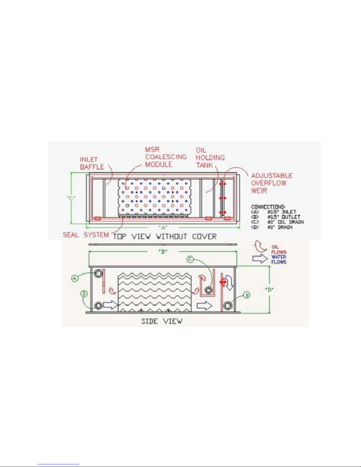
Check to ensure that the module has not moved out of place. The module
should be positioned so that it is correctly in position as shown on the
drawing.
Ensure that the corrugated and flat plastic side seal plates are correctly
installed. It is important that both of these should be flush against the
bottom of the separator. A small piece of wood such can be a convenient
way to push down on the top of the corrugated plates to get them to the
bottom of the separator without damaging the corrugations.
INITIAL START-UP
This procedure is to be followed after the installation of the separator or after the
separator has been drained and is ready to be restarted.
Before starting the flow to the unit, open or remove the cover and ensure
that the coalescing module has not shifted and that the corrugated plastic
is in place. The separator should contain one coalescing module, and the
corrugated plastic sheet between the module and the tank wall.
Ensure that there are no obstructions in the water outlet hose/piping and
that adequate oil disposal facilities are provided. Note: Pump adjustment will
be required (if provided), so it is advisable not to hard pipe the outlet water flow at
this time.
Fill the separator tank with clean water to avoid contaminating the
downstream end of the separator with oil. This should be filled to the point
where it overflows the outlet weir into the sewer.
Provide a source of clean water for flow adjustment.
Adjust the pump flow to 15 US GPM (or lesser desired flow). Test flow by
using the “bucket and stopwatch” method. Greater flows may damage
separation efficiency.
Adjust for the desired flow rate as above and allow unit to stabilize for a
few minutes.
Check to ensure that the stabilized water level is at least 1/8" below the oil
overflow weir. Water should not overflow into the oil collection tank – if this
happens, the flow is too great, the system is not level, or the overflow weir
is adjusted incorrectly.
Check for leaks, both external and internal and remedy any found.
At this point, the separator is ready for actual use. The only difference between
operations and the flow setting above is that oil will build up on the surface of the
water and eventually overflow into the oil collection tank.
Check to ensure that oil is building up on the surface of the water. If oil
buildup is very slow, ensure that there is no oil in the outlet water flow. If

the outlet water is clean, wait for oil to build up on the surface. If the outlet
flowing water contains oil, check for emulsification of oil and upstream
conditions. Ensure that emulsifying detergents are not being used in the
inlet water.
NORMAL OPERATION
Carefully maintain flow at the rate set when flow was established, or less. The oil
flow into the skimmer/oil tank, once a sufficient quantity of oil has accumulated in
the separator, varies with the concentration of oil in the incoming water. Only oil
will be removed, since the skimmer has been installed above the water level.
Some traces of water will exist in the oil because some of the water will become
entrained in the oil going over the weir. This is not a problem as long as it is not
too great because the oil should be recycled. If excessive water is found, check
the water weir adjustment. NOTE: An oil layer will always remain on the surface.
MAINTENANCE
1. After approximately 250 hours of operation, the inlet area of the separator
should be checked to determine if an excessive amount of solids have
accumulated. If this happens, the solids may accumulate enough to plug
the lower part of the module. In this case, efficiency will be reduced and
hydrocarbons in the outlet water may exceed allowable limits.
2. After approximately the first 250 hours of operation, the system should be
cleaned as follows:
a. Stop flow to the unit.
b. Remove system cover.
c. Drain the system using the plug at the front of the separator.
d. Remove the seal and coalescing module and clean the module.
Please note the module can be heavy and careful lifting methods
should be used. Always lift safely. The module can be cleaned
using a standard garden hose at normal domestic pressure. DO
NOT USE DETERGENTS OR SOAPS. DO NOT DISASSEMBLE
MODULE. It is not necessary to return the module to as-new
condition or to remove all of the oil, only to remove the solid
particles that may be present in the module. Some oil on the plates
will not cause deterioration of performance.
e. Use a hose to flush the tank and sweep all sediment out of the
drain connections.
f. To restart unit, reinstall module and seals. To reinstall module, use
the following steps:
i. Install module, being careful to install the module with the flat
metal plate down. Move the module to the side of the
module area.
ii. Install the corrugated plastic sheet between the module and
the wall.

iii. For start-up, follow instructions listed in the Initial Start-up
section above.
Note: The quantity of sludge found in the inlet section should be used as a basis for
determining the next interval before cleaning. If the sludge level is very low, the interval
can be extended. If it is more than 1/4 up the plate packs, the interval should be shortened.
TROUBLESHOOTING
Problem
Possible Cause
Diagnostic
Technique
Corrective
Action
Processed water
effluent contains
oil
Flow too great for
separator
Check flow rate
Reduce flow rate
Module plates
blocked
Remove module
and inspect
Clean system per
instructions
above and
reinstall
Seal corrugated
plate not installed
or incorrectly
installed
Inspect for
correct
installation
Install correctly
Surfactants
(soaps and
detergents) in
use upstream of
separator
Determine if
soaps or
detergents are in
use
Eliminate use of
soaps and/or
detergents
Tank overflowing
Outlet line
restricted or
blocked (2)
Check flow
Remove
restriction and/or
clean line
Pump flow too
great
Check flow
Adjust flow per
instructions
above
For other problems or advice, please consult with MSR at (918) 299-9290
Notes:
1. For oil flow, the oil layer on top of the water in the main separator area must be
at least 3/8” thick. Oil layer thickness for flow will depend on the specific
gravity of the oil removed.
2. Outlet line must be at least as large as outlet nozzle unless unit is operated at
very low flows.
Table of contents
Other MSR Water Filtration System manuals
Popular Water Filtration System manuals by other brands

PROSEP FILTER SYSTEMS
PROSEP FILTER SYSTEMS RP65139715 Installation & operating instructions

Prozone
Prozone CSS 10 owner's manual

Hagen
Hagen ELITE MINI Installation and operation

Zodiac Pool Systems
Zodiac Pool Systems Nature2 CF owner's manual

Industrial Separation Systems
Industrial Separation Systems VGS Technical manual

Enpress
Enpress CTA0840BBBKP5-04C00 Installation and operation manual