MS-01D Pro
ON ROAD USE ONLY
FULL BALL BEARINGS
※Specifications are subject to change without notice.
210102
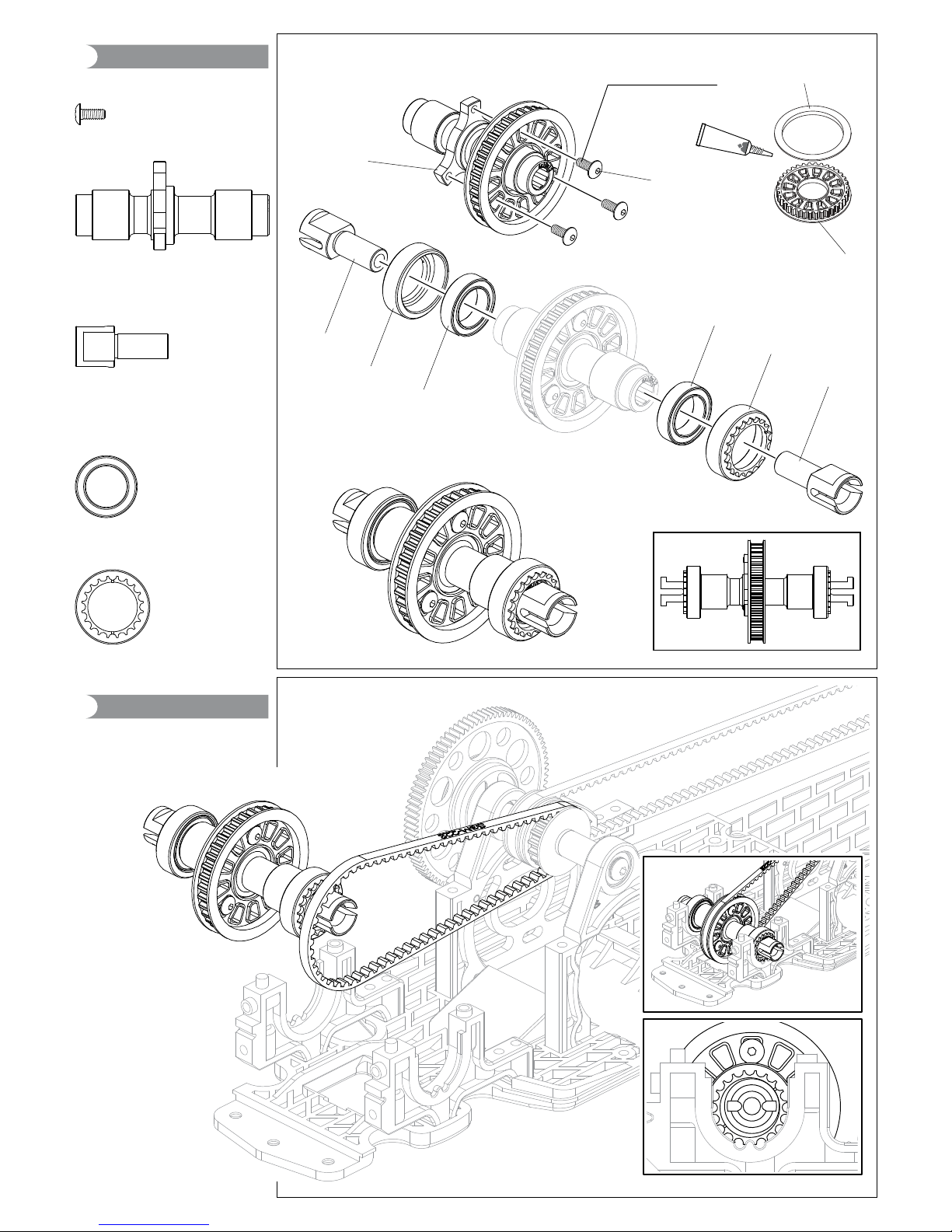
One Way Unit
鋁合金前單向組
210125
Carbon Front
Upper Deck
碳纖維二樓板 F 210117 & 210116
Spur Gear Holder & Cover
鋁合金大齒固定板
鋁合金大齒固定座
210114
Alum Motor Heat
Sink Mount
鋁合金馬達散熱固定座
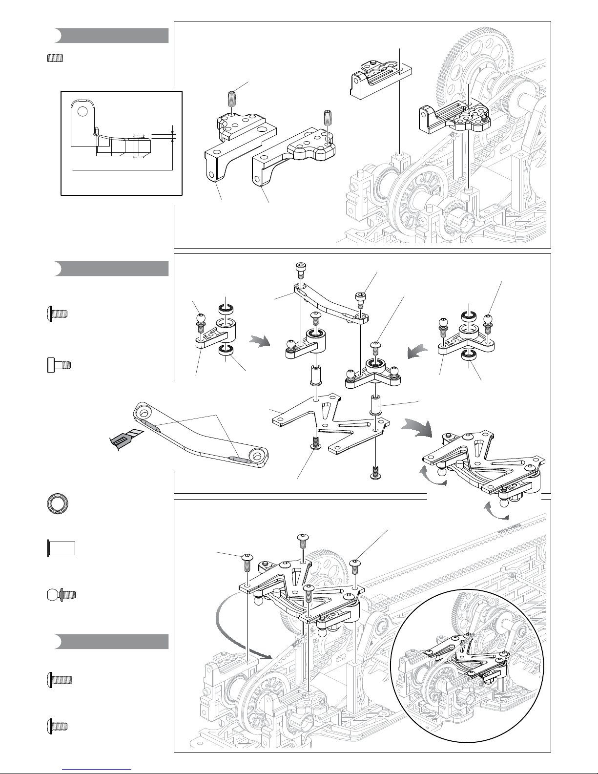
210101
Alum Servo Mount
鋁合金伺服機座
210123
Alum Belt Stabilizer Mount
鋁合金可調後皮帶壓輪座
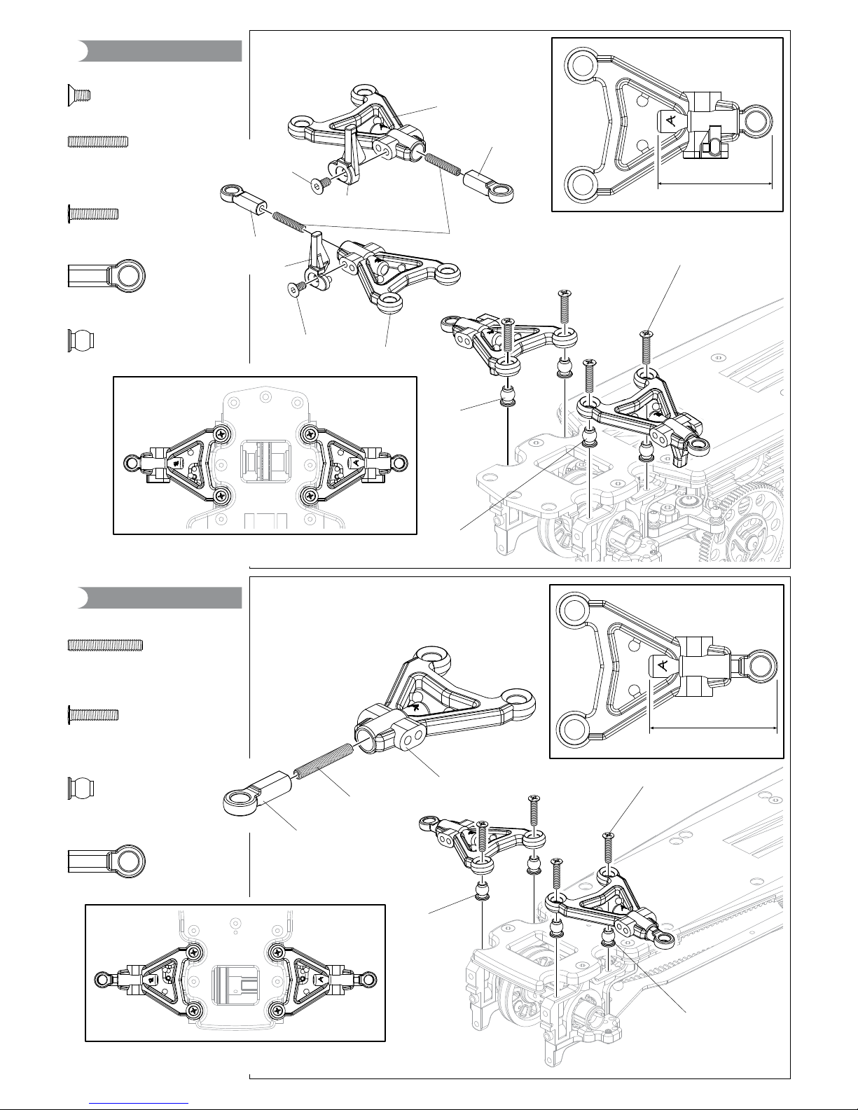
210106S & 210107S
F&R Steel Turn-Buckle Shaft
前後鋼製可調拉桿
210126
Carbon Rear Upper Deck
碳纖維二樓板 R
210112
Main Shaft Mount
Supporting Bar
主軸座支撐桿
210146
60deg Universal Shaft Set
大角度CVD傳動軸組
210145
Brake Calipers
煞車卡鉗
101005S
Great Angle Tire S
大角度甩尾胎S(軟)
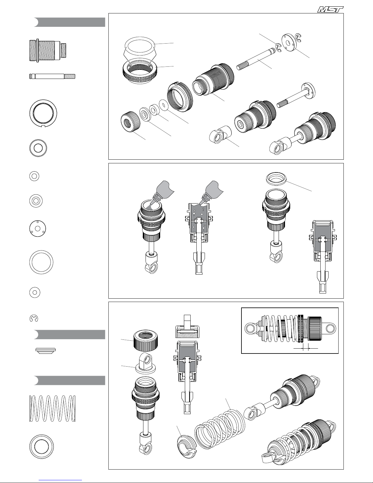
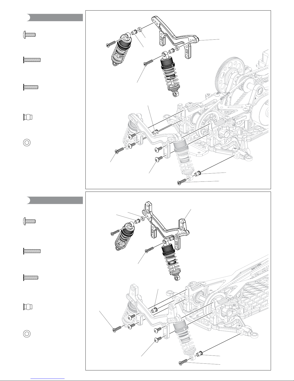
210115
Alum Damper Set
鋁合金避震器組
* 210111 CS pulley set (1.51/1.66/1.82) &
210145 Brake calipers are also included.
另附反胎齒比組與煞車卡鉗組。
1 / 10 SCALE RC 4WD HIGH PERFORMANCE DRIFT CAR
1 / 10 DRIFT CHASSIS KIT