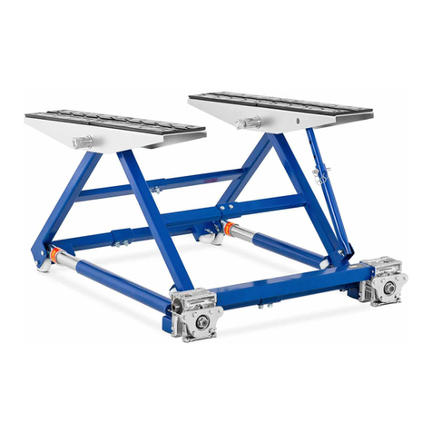
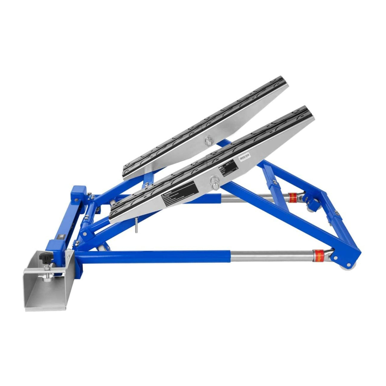
MSW MSW-MHB-360-780 User manual

User manual | Manuel d´utilisation | Istruzioni per l‘uso | Manual de instrucciones | Instrukcja obsługi | Návod k použití
BEDIENUNGSANLEITUNG
MSW MOTOR TECHNICS

2
INHALT | CONTENU | CONTENT | CONTENUTO | CONTENIDO | TREŚĆ
Deutsch
English
Polski
Italiano
Español
Français
Rev. 09.12.2016
3
14
26
38
50
62
74
3
Rev. 09.12.2016
HINWEIS
In der vorliegenden Anleitung sind Beispielbilder vorhanden, die von dem tatsächlichen Aussehen der
Maschine abweichen können. Die ursprüngliche Bedienungsanleitung ist die deutschsprachige Fassung.
Sonstige Sprachfassungen sind Übersetzungen aus der deutschen Sprache.
1. Vor der Inbetriebnahme bitte die vorliegende Anleitung genau lesen! Bitte alle Sicherheitshinweise
beachten, um eventuelle Schäden infolge nicht bestimmungsgemäßer Verwendung zu vermeiden!
2. Die Bedienungsanleitung zum späteren Gebrauch aufbewahren. Sollte die Maschine Dritten übergeben
werden, ist die Bedienungsanleitung ebenfalls weiterzuleiten.
3. Sollte die Maschine nicht bestimmungsgemäß verwendet oder falsch bedient werden, ist die Haftung
des Herstellers für die eventuellen Schäden ausgeschlossen.
4. Die Maschine darf durch entsprechend geschulte, zur Bedienung geeignete und physisch
gesunde Personen bedient werden, die die vorliegende Anleitung gelesen haben und die
Arbeitsschutzanforderungen kennen.
5. Die Maschine ist nicht dazu bestimmt, durch Personen (darunter Kinder) mit eingeschränkten
physischen, sensorischen und geistigen Fähigkeiten bzw. durch Personen ohne entsprechende Erfahrung
und/oder entsprechendes Wissen bedient zu werden, es sei denn es gibt eine für ihre Aufsicht und
Sicherheit zuständige Person bzw. sie haben von dieser Person entsprechende Hinweise in Bezug auf
die Bedienung der Maschine erhalten.
II. REGELUNGEN ZUR SICHEREN NUTZUNG / WARNUNGEN
1. Vor jeder Verwendung sind die Anleitung und Sicherheitshinweise zu lesen.
2. Vor jeder Verwendung ist die Maschine in Bezug auf mögliche Beschädigungen, die den Betrieb
ausschließen, zu überprüfen. Verboten ist der Betrieb der Maschine, wenn Beschädigungen oder
Abnutzungen ihrer Bestandteile festgestellt werden, die den richtigen Betrieb verhindern.
3. Wurde die Maschine übermäßig belastet bzw. starken Erschütterungen ausgesetzt, muss sie durch den
zuständigen Service-Mitarbeiter vor der erneuten Inbetriebnahme überprüft werden.
4. Verboten ist der Betrieb einer beschädigten, abgenutzten oder falsch funktionierenden Maschine.
In diesem Fall ist die Maschine dem für Service zuständigen Unternehmen zwecks Reparatur und
Inspektion zu übergeben.
5. Man sollte periodisch umfassende Inspektionen der Maschine durchführen und die beschädigten/
abgenutzten Bauteile immer austauschen.
6. Demontieren und tauschen Sie keine Teile der Maschine.
7. Man darf ausschließlich die durch den Hersteller empfohlenen Ersatzteile verwenden.
8. Die Maschine darf ausschließlich durch die Personen bedient werden, die in Bezug auf
Sicherheitsregelungen geschult wurden und zur Bedienung physisch geeignet sind.
9. Verboten ist die Belastung der Maschine mit einer Last, die ihre max. Tragfähigkeit überschreitet.
10. Gegen den Heber oder die an ihm befestigte Ladung darf man nicht schlagen.
11. Dritte sind vor dem Betrieb der Maschine zu warnen. Diese Personen sollten sich in sicherer
Entfernung von der Ladung benden.
12. Verboten ist das Anheben von Menschen oder Tieren unter Verwendung dieser Maschine.
NAZWA PRODUKTU
Bedienungsanleitung sorgfältig lesen
Das Gerät entspricht der CE-Erklärung
Achtung! Stellen Sie sicher, das Dritte Abstand vom Arbeitsort halten
Achtung, Unfallgefahr!
Achtung, die Hand kann gequetscht werden!
Achtung, Schutzhelm tragen!
Achtung, Schutzschuhe tragen!
Achtung, Schutzhandschuhe tragen!
I. SICHERHEITSHINWEISE

4
13. Verboten ist das Lastanheben unter Verwendung der Maschine über Menschen oder Tieren.
14. Die Last ist immer zu beobachten.
15. Verboten ist, die Last ohne Aufsicht zu hinterlassen.
16. Man darf die zulässige Tragfähigkeit des Hubgeräts nicht überschreiten.
17. Man darf die Maschine nicht mit einer Last lagern.
18. Man darf nur eine Ladung auf einmal heben.
19. Es dürfen keine Modizierungen an der Maschine vorgenommen werden.
20. Nach dem Abschluss des Betriebs ist die Maschine gegen unbefugte Benutzung abzusichern.
21. Die Maschine muss regelmäßig überprüft werden, beschädigte oder abgenutzte Bestandteile müssen
durch die zuständige Service-Stelle gegen neue ausgetauscht werden.
22. Beim Herunterfallen der Last entsteht Todes- oder Verletzungsrisiko.
23. Wird der Motorradheber über längere Zeit nicht verwendet wird, ist sicher zu stellen, dass er sauber
ist, keine Verschmutzungen aufweist und das der Sattel in die niedrigste Position gebracht wurde. Das
Gerät darf nicht mit Feuchtigkeit in Kontakt kommen, ggf. ist es trocken zu reiben, danach sämtliche
beweglichen Teile schmieren.
24. Die Beladung sollte stets mit einer Kette gesichert werden.
25. Die Maschine darf ausschließlich auf einer achen, horizontalen und der Belastung angepassten
Oberäche verwendet werden.
26. Die Beladung sollte stets gut ausgewogen sein. Die Empfehlungen des Motorradherstellers bezüglich
der Motorradhebepunkte müssen befolgt werden.
27. Es ist untersagt, den Motorradheber zusammen mit der Beladung zu verlegen/zu transportieren! Ein
Verlegen / Transport darf ausschließlich ohne Beladung erfolgen.
28. Nähern Sie nie die Hände oder Beine dem Arbeitsbereich.
29. Es ist untersagt, die Maschine zu verändern. Es ist untersagt, die Maschine zu verwenden, wenn
sichtbare Beschädigungen vorliegen, die Verformung von Teilen, Risse oder andere Defekte, die eine
ordnungsgemäße Verwendung unmöglich machen.
30. Vor Verwendung der Maschine muss überprüft werden, ob alle Schrauben fest angezogen sind.
Werden die Anweisungen und Sicherheitshinweise verletzt kann das zu ernsthaften Körperverletzungen
oder zum Tod führen.
III. MASCHINENBESTIMMUNG
Der Motorradheber dient ausschließlich zum Anheben von Motorrädern. Eine Verwendung zu anderen
Zwecken ist untersagt.
Für alle Schäden bei nicht bestimmungsgemäßer Verwendung haftet allein der Benutzer.
IV. TECHNISCHE DATEN
Produktname Motorradhebebühne
Modell MSW-MHB-360-780 MSW-MHB-450-680 MSW-MHB-135 MSW-MHB-135-PRO
Katalognummer 6314 6315 6316 6317
Maximal zulässige
Belastung (lbs/kg)
360 450 135 135
Maximale Höhe (cm) 78 68 87 87
Minimale Höhe (cm) 21 18 35 35
Gewicht (kg) 105 114 28 29
Plattformgröße (cm) 175x50 190x53 41x35 41x35
Größe der Auaufram-
pe (cm)
45x50 42x53 - -
Rev. 09.12.2016 5
Rev. 09.12.2016
Detailzeichnung:
MSW-MHB-360-780 (6314)
5
1
2
3
4
5
6
7
8
9
10 11 12 13 14 15
16 17 18 19
20 21 22
23
24 25 26
27 28 29 30 31 32 33 34 35 36
39
38
37
40
43
42
41
46
44 45
47484950515253
54
55
56
57
58
59
60
61
62
63
Nr. Beschreibung Menge
1Sicherungsstange 1
2Tragarm 1
3 Rolle 2
4Tragarm 1
5Bolzen 1
6Unterlegscheibe 2
7Stift 2
8 Rolle 2
9Pumpe 1
10 Stift 2
11 Unterlegscheibe 2
12 Rad 2
13 Schraube M16X90 1
14 Unterlegscheibe 1
15 Mutter M16 1
Nr. Beschreibung Menge
16 Feder 1
17 Elemente - Ölablass 1
18 Schraube M16 1
19 Komponenten des Entriegelungshebels 1
20 Schraube M5X10 1
21 Schraube M10x40 1
22 Mutter M10 1
23 Walze 1
24 Schraube M16X45 2
25 Unterlegscheibe 2
26 Mutter M16 2
27 Unterlegscheibe 8
28 Schraube M6X10 8
29 Rad 2
30 Prol 2

6Rev. 09.12.2016 7
Rev. 09.12.2016
Nr. Beschreibung Menge
1Schraube M12×20 2
2Unterlegscheibe 12 40
3Schraube M12×30 8
4Unterlegscheibe 2
5Federscheibe 10 2
6 Mutter M10 2
7Tragarm 2
8Stellschraube 3
9Unterlegscheibe M6 3
10 Mutter M6 3
11 Rad 2
12 Unterlegscheibe 8 4
13 Schraube M8×18 1
14 Entriegelungsventil 1
15 Entriegelungs- Fußhebel 1
16 Spindelkolbenpumpe 1
17 Welle 1
18 Fußhebel 1
19 Feder 1
20 Verbindungsstück 1
21 Stift 8
22 Flexibler Feststellring 12 16
23 Mutter M20 2
24 Rad 2
Nr. Beschreibung Menge
25 Unterlegscheibe 14 4
26 Flexibler Stabilisierungsring 14 2
27 Tragarm 2
28 Rahmen 2
29 Mutter M12 16
30 Schraube M8×35 4
31 Ölablass 1
32 Mutter M8 4
33 Hinterer Tragarm 1
34 Welle 1
35 Unterlegscheibe 4
36 Flexibler Stabilisierungsring 20 2
37 Schraube M10×10 2
38 Verbindungselemente 1
39 Pumpe 1
40 Aufrolläche 1
41 Bewegliche Platte 1
42 Plattform 1
43 Klemmenregulierung 1
44 Begrenzer 1
45 Klemmenachse 1
46 Untere Klemmenpkatte 1
47 Vorderer Tragarm 1
48 Federscheibe 10 2
MSW-MHB-450-680 (6315)
1
29
2
3
4
5
6
7
8
9
10
11
48
13
14
15
16
17
18
19
20
21
3
22
23 24 25 26 2 27 28 3 29
30
12
31
32
33
34
35
36
37
38
39
4041424321098
44
29
3
45
21
3
22
46
47
Nr. Beschreibung Menge
31 Stift 2
32 Schraube M8X15 2
33 Begrenzer 2
34 Schraube M10X20 4
35 Unterlegscheibe Ø10 4
36 Zwischenwelle 2
37 Schraube M16X80 1
38 Unterlegscheibe Ø16 1
39 Mutter M16 1
40 Aufrolläche 1
41 Schraube M16X45 2
42 Unterlegscheibe Ø16 2
43 Mutter M16 2
44 Mutter M8 16
45 Unterlegscheibe Ø8 16
46 Rohrhalter 4
47 Mutter 10
48 Unterlegscheibe Ø10 11
Nr. Beschreibung Menge
49 Bewegliche Platte 2
50 Schraube M6X16 12
51 Schraube a M10x30 8
52 Bewegliches Spanneisen 1
53 Bewegliches Spanneisen 1
54 Begrenzer 1
55 Schraube M10X30 2
56 Unterlegscheibe Ø10 2
57 Mutter M10 2
58 Gewindestange 1
59 Klemme 1
60 Unterlegscheibe Ø14 1
61 Halter 1
62 Unterlegscheibe Ø10 1
63 Mutter M10 1

1
2
3
4
5
6
7
8
9
10
11
12
13
14
15
16
17
18
19
20
21
22
23 24 25 26
27
28
29
30
31
32
33
34
35
36
8Rev. 09.12.2016 9
Rev. 09.12.2016
MSW-MHB-135-PRO (6317)
Nr. Beschreibung Menge
1Gummikappe 1
2Stahlplatte 1
3Oberer Rahmen 1
4Unterlegscheibe M12 2
5Federscheibe 12 2
6 Mutter M12 4
7Platte 2
8 Obere Rolle 2
9Stift 1
10 Feststellblock 8
11 Untere Rolle 2
12 Pumpe 1
13 Schraube M12 1
14 Gummikappe - Fußhebel 1
15 Fußhebel 1
16 Federstift 1
17 Ablassventil 1
18 Verbindungsplatte 1
Nr. Beschreibung Menge
19 Verbindungsstift 1
20 Splint 2
21 Unterlegscheibe M8 2
22 Schraube M8x25 2
23 Verriegelungshebel 1
24 Grundrahmen 1
25 Mutter M5 4
26 Unterlegscheibe M5 4
27 Schraube M5x40 4
28 Mutter M8 2
29 Unterlegscheibe M8 1
30 Schraube M8x12 1
31 Mutter M12 1
32 Anhebe-Vorrichtung 1
33 Feder mit Haken 2
34 Mutter 2
35 Unterlegscheibe 2
36 Schraube 2
MSW-MHB-135 (6316)
Nr. Beschreibung Menge
1Gummikappe 1
2Stahlplatte 1
3Oberer Rahmen 1
4Unterlegscheibe M8 8
5Knebelgriff mit Gewinde 2
6Unterlegscheibe 2
7Rohrhalter 2
8 Haken 2
9 Obere Rolle 2
10 Feststellblock 8
11 Untere Rolle 2
12 Pumpe 1
13 Schraube M12 1
14 Gummikappe - Fußhebel 1
15 Fußhebel 1
16 Bolzen 1
17 Fußhebel 1
18 Verbindungsplatte 1
Nr. Beschreibung Menge
19 Verbindungsplatte 1
20 Splint 2
21 Unterlegscheibe M8 2
22 Schraube M8x25 2
23 Verriegelungshebel 1
24 Grundrahmen 1
25 Mutter M5 8
26 Unterlegscheibe M5 8
27 Unterlegscheibe M10 16
28 Mutter M10 16
29 Rad 4
30 Schraube M10x20 16
31 Schraube M5x45 8
32 Mutter M8 2
33 Unterlegscheibe M8 1
34 Schraube M8x12 1
35 Mutter M12 1
36 Anhebe-Vorrichtung 1
1
2
3
4
5
6
7
8
9
10
11
12
13
14
15
16
17
18
19
20
21
22
23 24 25 26 27 28 29
30
31
32
33
34
35
36

1
2
3
4
5
6
12
3
4
5
10 Rev. 09.12.2016 11
Rev. 09.12.2016
12345
6
7
89
10
Vor dem Gebrauch muss überprüft werden, ob Gewicht und Größe des Motorrads nicht die nominale
Tragkraft des Hebers übersteigt.
Vor der Inbetriebnahme zum Anheben ist die Hebevorrichtung vor unbeabsichtigtem Wegrutschen zu
sichern.
Den Motorradheber nur auf stabilen und ebenen Flächen verwenden.
Den Motorradheber nur ohne Beladung transportieren; die Plattform sollte auf das unterste Level
abgelassen werden.
Der Heber kann nur auf einer stabilen und trockenen Oberäche verwendet werden, die nicht rutschig und
in der Lage ist, das Gesamtgewicht des Aufzugs und der Last zu tragen. Das Gerät muss sauber gehalten
werden. Keine Gegenstände darauf lagern, die bei der Arbeit nicht erforderlich sind.
Das Motorrad muss sicher und fest auf der Plattform angebracht werden. Hierzu die Befestigungsriemen
verwenden und diese an den Halterungen des Hebers befestigen.
Vor dem Ablassen der Plattform alle sich darunter bendenden Gegenstände entfernen. Alle Personen
sollten sich während des Betriebs des Hebers in sicherem Abstand benden.
Es ist untersagt, den Heber oder die Plattform zum Transport von Gegenständen zu verwenden. Das Gerät
ist ausschließlich zum stationären Gebrauch gedacht - zum Anheben von Gegenständen. Die angehobene
Beladung muss stets stabil sein.
Sämtliche Reparaturen müssen von qualiziertem technischen Personal durchgeführt werden; die
Austauschteile müssen Originalteile und vom Hersteller des Gerätes zugelassen sein.
Der Motorradheber muss auf einem festen und ebenen Untergrund aufgestellt werden, welcher
das Gesamtgewicht der Last (Heber zusammen mit der Beladung) halten kann. Der Heber ist gegen
unbeabsichtigtes Wegrutschen oder Verschieben zu sichern.
Die Beladung (Motorrad) auf der Plattform unterbringen und sichern, indem das Vorderrad des Motorrads
in dem Schraubstock [nur die Modelle: MSW-MHB-360-780 (6314) / MSW-MHB-450-680 (6315)] befestigt
wird. Befestigen sie das Motorrad auch mit den Riemen / Befestigungskomponenten.
Die Plattform durch energisches Pumpen des Fußhebels anheben. Wenn die Plattform in der gewünschten
Höhe ist, die Sicherungsstange in eine der Öffnungen in der Plattform schieben. Dies ist eine Absicherung
gegen zufälliges Absacken oder Verschieben:
Nach abgeschlossener Arbeit sicherstellen, dass der Raum unter der
Plattform frei ist und die Hebebühne gefahrlos abgelassen werden
kann. Die Sicherungsstange herausziehen und den Fußhebel zum
Öffnen der Sperre langsam betätigen (oder den Drehknopf - je nach
Modell). Die Plattform langsam ablassen.
Das Modell MSW-MHB-450-680 (6315) ist mit einem Geschwindigkeitsregler zum Ablassen ausgestattet:
HINWEIS
SCHNELLER LANGSAMER
Die Schrauben nicht ganz festziehen
um ein blockieren zu vermeiden.
VI. ZUSAMMENBAU DER MASCHINE
Prüfen Sie bei Erhalt der Ware zuerst die Verpackung auf Unversehrtheit und öffnen Sie diese dann. Wenn
die Verpackung Beschädigungen aufweist, so setzen Sie sich innerhalb von 3 Tagen mit der Transportgesell-
schaft und Ihrem Vertriebspartner in Verbindung und dokumentieren Sie so gut wie möglich die Beschädi-
gungen. Stellen Sie das volle Paket nicht verkehrt herum auf! Sollten Sie das Paket weiter transportieren,
achten Sie bitte darauf, dass es horizontal und stabil gehalten wird. Es wird darum gebeten, das Verpa-
ckungsmaterial (Pappe, Plastikbänder und Styropor) zu behalten, um im Servicefall die Maschine bestmög-
lich geschützt zurücksenden zu können!
VI. ZUSAMMENBAU DER MASCHINE
MSW-MHB-360-780 (6314) / MSW-MHB-450-680 (6315):
1. Rad
2. Fußhebel - Anhebevorrichtung
3. Fußhebel - Entriegelung
4. Regulierungsventil der Ablassgeschwindigkeit der Plattform[nur Modell: MSW-MHB-450-680 (6315)]
5. Pumpe
6. Aufrolläche
7. Plattform
8. Montagehalterungen - Motorrad
9. Feststeller
10. Begrenzer
1. Fußhebel / Drehknopf zur Entriegelung
2. Fußhebel der Anhebe-Vorrichtung
3. Anhebe-Vorrichtung
4. Feststellelemente
5. Hebeplatte
6. Sicherheitsstange
MSW-MHB-135 (6316) / MSW-MHB-135-PRO (6317)

12 Rev. 09.12.2016
LAGERUNG
Die Maschine ist immer ohne Last zu lagern. Verschmutzungen sind zu beseitigen. Die Maschine ist an einer
trockenen Stelle aufzuhängen. Vor der erneuten Benutzung hat man gemäß den Anweisungen zu verfahren,
die in der vorliegenden Anleitung beschrieben wurden.
INSPEKTIONEN
Vor der Inbetriebnahme muss eine neue oder reparierte Maschine durch qualiziertes technisches Personal
mit entsprechendem Wissen und Erfahrung in Bezug auf Bedienung und Wartung der Maschinen dieses Typs
überprüft werden. Die Maschine ist regelmäßigen Sichtkontrollen vor, während und nach der Benutzung zu
unterziehen. Für die Inspektion ist das Bedienungspersonal zuständig. Alle Störungen des Maschinenbetriebs
sind dem zuständigen technischen Personal zu melden. Verboten ist der Betrieb beschädigter Maschinen, die
Störungen aufweisen.
GEFAHREN BEIM BETRIEB
Während des Betriebs können mechanische Gefahren auftreten. Diese entstehen, wenn es zu Verletzungen
infolge der mechanischen Auswirkung von unterschiedlichen Bauteilen kommen kann, z. B. der Maschinenteile,
Werkzeuge etc.
Grundsätzliche mechanische Gefahren sind: Quetschen, Zusammendrücken, Schneiden oder Abschneiden,
Schürfen, Stolpern und Schleudern.
Diese Gefahren können beim normalen und gestörten Betrieb der Maschine auftreten und zu
Maschinenstörungen führen.
Mechanische Gefahren können unter folgenden Umständen entstehen: sich bewegende Maschinen,
beförderte Ladungen, bewegliche Bestandteile, rohe/scharfe Bauteile, herabfallende Bestandteile/Ladungen,
unebene, glatte Oberächen, beschränkte Räume, Lage der Arbeitsstelle im Verhältnis zum Boden (Höhen-
und Tiefarbeiten).
VII. REINIGUNG UND WARTUNG
Die Motorrad-Hebebühne muss regelmäßig gereinigt werden. Nach Abschluss der Arbeiten müssen
sämtliche Rückstände von der Montageäche und aus dem Gerät selbst entfernt werden. Sämtliche
Wartungs- und Inspektionsarbeiten der Hebebühne sollten von geschultem und qualiziertem Personal
durchgeführt werden. Es sollte keine Person vornehmen, die keine Erfahrung und kein Wissen in diesem
Bereich hat.
Wenn die Hebeeffektivität der Hebebühne spürbar nachlässt ist das Ablassventil zu öffnen - dann den
Fußhebel 15 bis 20 Mal energisch bewegen, um das Hydrauliksystem zu entlüften.
VIII. REGELMÄSSIGE PRÜFUNG DER MASCHINE
Prüfen Sie regelmäßig, ob Elemente der Maschine Beschädigungen aufweisen. Sollte dies der Fall sein, darf die
Maschine nicht mehr benutzt werden. Wenden Sie sich umgehend an Ihren Verkäufer, um Nachbesserungen
vorzunehmen.
Was tun im Problemfall?
Kontaktieren Sie Ihren Verkäufer und bereiten Sie folgende Angaben vor:
• Rechnungs- und Seriennummer (letztere nden Sie auf dem Typenschild)
• ggf. ein Foto des defekten Teils
• Ihr Servicemitarbeiter kann besser eingrenzen worin das Problem besteht, wenn Sie es so präzise wie
möglich beschreiben. Je detaillierter Ihre Angaben sind, umso schneller kann Ihnen geholfen werden!
ACHTUNG: Öffnen Sie die Maschine niemals ohne Rücksprache mit dem Kundenservice. Dies kann Ihren
Gewährleistungsanspruch beeinträchtigen!
Nach dem Ende der Lebensdauer des Gerätes sollte es nicht als Hausmüll entsorgt werden. Aufgrund
des Umweltschutzes muss das Gerät an eine bestimmte Abfallstelle abgelagert werden. Detaillierte
Informationen zur Abfallentsorgung erhalten Sie in der Abfallberatung
13
Rev. 09.12.2016
MSW-MHB-360-780 (6314)
MOTORRAD-HEBEBÜHNE
MAXIMALE ZULÄSSIGE BELASTUNG 360 KG
VOR INBETRIEBNAHME DIE SICHERHEITSANWEISUNGEN DURCHLESEN
MSW-MHB-135 (6316) / MSW-MHB-135-PRO (6317):
MOTORRAD-HEBEBÜHNE
MAXIMALE ZULÄSSIGE BELASTUNG 135 KG
VOR INBETRIEBNAHME DIE SICHERHEITSANWEISUNGEN DURCHLESEN
MSW-MHB-450-680 (6315):
MOTORRAD-HEBEBÜHNE
MAXIMALE ZULÄSSIGE BELASTUNG 450 KG
VOR INBETRIEBNAHME DIE SICHERHEITSANWEISUNGEN DURCHLESEN

MSW MOTOR TECHNICS
USER MANUAL
MSW-MHB-360-780
MSW-MHB-450-680
MSW-MHB-135
MSW-MHB-135-PRO
15
Rev. 09.12.2016
PLEASE NOTE!
Drawings in this manual are for illustration purposes only and in some details it may differ from the actual
product. The original operation manual is in German. Other language versions are translations from German.
1. Before commencing with the work, make sure to read carefully and understand this operation manual!
All safety recommendations must be followed in order to avoid possible damages as a result of
improper use of the equipment.
2. Keep the instructions for future reference. If the machine is to be handed over to a third party, this
operation manual must also be handed over with the machine.
3. If the machine is operated contrary to its intended use or in case of improper handling of the machine,
the manufacturer's liability for possible damage is excluded.
4. The machine can be operated by physically t persons who have read this operating manual and who
are also familiar with the occupational health and safety requirements.
5. The machine is not designed to be handled by persons (including children) with limited physical,
sensory and mental abilities, or by persons lacking appropriate experience and/or knowledge, unless
they are supervised by a person responsible for their safety or if they have received instructions on
how to operate the machine
II. SAFE OPERATION PRINCIPLES / WARNINGS
1. Read this operation manual and the safety instructions prior to each use of the machine.
2. Before each use, the machine must be checked for possible damages that can result in a failure. This
machine must not be operated if its parts are worn out or damaged in a way that prevents proper
operation.
3. If the machine has been overloaded or subject to strong shock/vibrations, it must be inspected by a
qualied service technician before commencing any work on the machine.
4. This machine must not be operated if it is damaged, worn out or if it does not work properly. If such
condition occurs the machine must be handed over to an authorized service center for inspection and
repair.
5. Comprehensive periodic inspections of the machine must be carried out and worn out/damaged parts
must be always replaced.
6. Do not dismount or replace any parts of the machine.
7. Use only original replacement parts, as recommended by the manufacturer.
8. This machine may only be handled by persons properly trained in safety regulations and physically able
to operate the machine.
9. Do not overload the machine with a load exceeding the maximum admissible load.
10. Do not hit the lift or the load.
11. Third parties must be warned about operation of the machine and stay at a safe distance.
12. Do not lift people or animals using this machine.
13. Do not lift the load using the machine over people or animals.
14. Always pay attention to the load.
The operation manual must be read carefully.
This machine conforms to CE declaration.
Attention! Make sure that third parties keep distance from the area.
Attention! Risk accident
Caution, the hand can be squeezed!
Attention! Wear protective helmet.
Attention! Wear protective footwear
Attention! Wear protective gloves.
I. SAFETY RECOMMENDATIONS

16
15. Do not leave the load without supervision.
16. Never exceed the permissible lifting capacity.
17. Never store the machine with a payload attached to it.
18. Lift only one load at a time.
19. No modications should be made to the machine
20. After completion of the operation, the machine must be secured against unauthorized use.
21. The machine must be regularly inspected and its damaged or worn out and torn parts must be
replaced with new ones by an authorized service.
22. If the load falls, there is a risk of death or injury.
23. If the lift table remains unused for a long period of time, make sure it is clean and free from stains and
that the platform is in the lowest position. Avoid contact with moisture, wipe dry if needed and grease
all articulated parts.
24. Always secure the load with a chain.
25. The device should only be used on a at and level surface, with appropriate load bearing rating.
26. The load should always be correctly balanced. Follow motorcycle manufacturer’s instructions for lifting
points.
27. Do not move / transport the lift table with a load on it! The lift table may be moved / transported only
without a load.
28. Keep limbs away from the operating area.
29. Do not modify the device. Do not use the device if any parts are deformed, damaged cracked or if
other faults occur which prevent correct operation.
30. Make sure all the bolts are securely tightened prior to use.
Failure to follow safety recommendations and instructions may result in serious injuries or death!
III. INTENDED USE OF THE MACHINE
The motorcycle lift is designed for lifting motorcycles. Do not use the lift table for any other purpose.
The user is responsible for any damages resulting from a non-conform use of the device!
IV. TECHNICAL SPECIFICATIONS
Product name Motorcycle lift
Model MSW-MHB-360-780 MSW-MHB-450-680 MSW-MHB-135 MSW-MHB-135-PRO
Art. No: 6314 6315 6316 6317
Maximum loading
(lbs/kg)
360 450 135 135
Maximum height (cm) 78 68 87 87
Minimum height (cm) 21 18 35 35
Weight (kg) 105 114 28 29
Table size (cm) 175x50 190x53 41x35 41x35
Ramp size (cm) 45x50 42x53 - -
Rev. 09.12.2016 17
Rev. 09.12.2016
Assembly diagrams:
MSW-MHB-360-780 (6314)
5
1
2
3
4
5
6
7
8
9
10 11 12 13 14 15
16 17 18 19
20 21 22
23
24 25 26
27 28 29 30 31 32 33 34 35 36
39
38
37
40
43
42
41
46
44 45
47484950515253
54
55
56
57
58
59
60
61
62
63
No. Description Quantity
1Locking bar 1
2Lifting arm 1
3 Roller 2
4Lifting arm 1
5Pin 1
6Ø16 washer 2
7 Mandrel 2
8 Roller 2
9Pump 1
10 Mandrel 2
11 Ø12 washer 2
12 Wheel 2
13 M16X90 bolt 1
14 Ø16 washer 1
15 M16 nut 1
No. Description Quantity
16 Spring 1
17 Oil discharge elements 1
18 M16 bolt 1
19 Release lever elements 1
20 M5X10 bolt 1
21 M10x40 bolt 1
22 M10 nut 1
23 Spindle 1
24 M16X45 bolt 2
25 Ø16 washer 2
26 M16 nut 2
27 Ø16 washer 8
28 M6X10 bolt 8
29 Wheel 2
30 Bottom support 2

18 Rev. 09.12.2016 19
Rev. 09.12.2016
MSW-MHB-450-680 (6315)
1
29
2
3
4
5
6
7
8
9
10
11
48
13
14
15
16
17
18
19
20
21
3
22
23 24 25 26 2 27 28 3 29
30
12
31
32
33
34
35
36
37
38
39
4041424321098
44
29
3
45
21
3
22
46
47
No. Description Quantity
1M12×20 bolt 2
212 washer 40
3M12×30 bolt 8
410 washer 2
510 spring washer 2
6 M10 nut 2
7Bracket 2
8Adjustment bolt 3
9M6 washer 3
10 M6 nut 3
11 Wheel 2
12 8 washer 4
13 M8×18 bolt 1
14 Lock release valve 1
15 Release foot pedal 1
16 Pump piston spindle 1
17 Shaft 1
18 Lift foot pedal 1
19 Spring 1
20 Connector 1
21 Mandrel 8
22 12 exible adjustment ring 16
23 M20 nut 2
24 Wheel 2
No. Description Quantity
25 14 washer 4
26 14 stabilising spring washer 2
27 Bracket 2
28 Support frame 2
29 M12 nut 16
30 M8×35 bolt 4
31 Oil discharge 1
32 M8 nut 4
33 Rear support bracket 1
34 Shaft 1
35 20 washer 4
36 20 stabilising spring washer 2
37 M10×10 bolt 2
38 Connecting elements 1
39 Pump 1
40 Ramp 1
41 Access Panel 1
42 Table 1
43 Vice adjustment elements 1
44 Stop bracket 1
45 Vice axis 1
46 Lower vice plate 1
47 Front support bracket 1
48 10 spring washer 2
No. Description Quantity
31 Mandrel 2
32 M8X15 bolt 2
33 Stop 2
34 M10X20 bolt 4
35 Ø10 washer 4
36 Shaft socket 2
37 M16X80 bolt 1
38 Ø16 washer 1
39 M16 nut 1
40 Ramp 1
41 M16X45 bolt 2
42 Ø16 washer 2
43 M16 nut 2
44 M8 nut 16
45 Ø8 washer 16
46 U-clamp 4
47 Nut 10
48 Ø10 washer 11
No. Description Quantity
49 Access Panel 2
50 M6X16 bolt 12
51 M10x30 bolt 8
52 Vice 1
53 Vice 1
54 Stop plate 1
55 M10X30 bolt 2
56 Ø10 washer 2
57 M10 nut 2
58 Threaded rod 1
59 Clamp 1
60 Ø14 washer 1
61 Handle 1
62 Ø10 washer 1
63 M10 nut 1

1
2
3
4
5
6
7
8
9
10
11
12
13
14
15
16
17
18
19
20
21
22
23 24 25 26
27
28
29
30
31
32
33
34
35
36
20 Rev. 09.12.2016 21
Rev. 09.12.2016
MSW-MHB-135-PRO (6317)
No. Description Quantity
1Rubber overlay 1
2 Steel plate 1
3Upper support frame 1
4M12 washer 2
512 spring washer 2
6 M12 nut 4
7Bracket 2
8 Upper roller 2
9 Mandrel 1
10 Retention block 8
11 Bottom roller 2
12 Pump 1
13 M12 bolt 1
14 Pedal rubber overlay 1
15 Lift foot pedal 1
16 Spring pin 1
17 Release valve 1
18 Plate 1
No. Description Quantity
19 Connecting pin 1
20 Safety pin 2
21 M8 washer 2
22 M8x25 bolt 2
23 Locking lever 1
24 Bottom frame 1
25 M5 nut 4
26 M5 washer 4
27 M5x40 bolt 4
28 M8 nut 2
29 M8 washer 1
30 M8x12 bolt 1
31 M12 nut 1
32 Scissor system 1
33 Spring and hook 2
34 Nut 2
35 Washer 2
36 Bolt 2
MSW-MHB-135 (6316)
No. Description Quantity
1Rubber overlay 1
2 Steel plate 1
3Upper support frame 1
4M8 washer 8
5Threaded knob 2
6Washer 2
7U-clamp 2
8 Hook 2
9 Upper roller 2
10 Retention block 8
11 Bottom roller 2
12 Pump 1
13 M12 bolt 1
14 Pedal rubber overlay 1
15 Lift foot pedal 1
16 Pin 1
17 Release pedal 1
18 Plate 1
No. Description Quantity
19 Plate 1
20 Safety pin 2
21 M8 washer 2
22 M8x25 bolt 2
23 Locking bar 1
24 Bottom frame 1
25 M5 nut 8
26 M5 washer 8
27 M10 washer 16
28 M10 nut 16
29 Wheels 4
30 M10x20 bolt 16
31 M5x45 bolt 8
32 M8 nut 2
33 M8 washer 1
34 M8x12 bolt 1
35 M12 nut 1
36 Scissor system 1
1
2
3
4
5
6
7
8
9
10
11
12
13
14
15
16
17
18
19
20
21
22
23 24 25 26 27 28 29
30
31
32
33
34
35
36

12345
6
7
89
10
1
2
3
4
5
6
12
3
4
5
22 Rev. 09.12.2016
Before the use, ensure that the motorcycle weight and size do not exceed the lift capacity.
Secure the motorcycle lift against unintentional movement before lifting.
Only use the motorcycle lift on stable and even surfaces.
The lift may only be transported without load and with the table in the lowest position.
Only use the lift on a stable and dry surface, which is not slippery and is of sufcient load capacity for the
lift and its load. Keep the device clean. Do not keep items on the lift which are not essential to perform the
work.
Attach the motorcycle rmly and securely to the table. Use tie-down straps and U-clamps on the lift to do
that.
Before lowering the table, remove all items from under it. Keep at a safe distance from the lift when in
operation.
Do not use the lift or table to transport objects. The lift is designed to be used solely as a stationary device,
for lifting. Make sure the load to be lofted is stable.
All repairs have to be carried out by qualied technical personnel. Use only original replacement parts,
approved by the device manufacturer.
Position the loft on a rm and horizontal surface, with sufcient lead bearing for the weight of the lift and
the load; secure the lift against accidental movements.
Locate the load (motorbike) in the table and secure by clamping the front wheel in the vice [only MSW-
MHB-360-780 (6314) / MSW-MHB-450-680 (6315) models]. Also use tie-down straps / clamps to attach the
motorbike to the table.
Lift the table by rmly pressing on the lift pedal. Once the table is at the desired height, insert the locking
bar into one of the slots in the table. This secures the table from accidental release or movement:
Once work is complete, make sure there is nothing below the
table preventing the lift from being lowered. Remove the locking
bar and slowly press the release pedal (or knob, depending on the
motorbike lift model). Slowly lower the table.
MSW-MHB-450-680 (6315) has a table release speed adjustment facility:
WARNING
FASTER SLOWER
Do not screw nuts down competely
in order to avoid locking
23
Rev. 09.12.2016
V. BEFORE THE FIRST USE
Upon receipt of the goods, check the packaging for integrity and open it. If the packaging is damaged, please
contact your transport company and distributor within 3 days and document the damages as detailed as
possible. Do not turn the package upside down! When transporting the package, please ensure that it is
kept horizontal and stable. The various items used for packaging (cardboard, plastic straps, polyurethane
foam) should be conserved, so that the machine can be sent back to the service centre in the best condi-
tion in case of any problems!
VI. ASSEMBLING THE MACHINE
MSW-MHB-360-780 (6314) / MSW-MHB-450-680 (6315):
1. wheels
2. lift foot pedal
3. release foot pedal
4. table release speed adjustment valve [only for MSW-MHB-450-680 (6315) model]
5. pump
6. ramp
7. table
8. motorbike attachment U-clamps
9. vice
10. limiter
1. release foot pedal
2. lift foot pedal
3. scissor lift system
4. fasteners
5. table-top
6. locking bar
MSW-MHB-135 (6316) / MSW-MHB-135-PRO (6317)

24 Rev. 09.12.2016
STORAGE
The machine must always be stored without any load. The dirt must be removed. The machine must be
stored in a dry place. Before using the machine again, make sure to follow the instructions described in this
manual.
INSPECTIONS
Before being used, the new or repaired machine must be checked by qualied technical personnel who have
knowledge and experience within the scope of operation and maintenance of this type of machine.
The machine must be checked regularly by means of visual control of the machine’s condition, before, during
and after use.
The operator is responsible for the inspection. Any irregularities of the machine operation, as well as any
damages, must be reported to the proper technical personnel. Do not use the machine if it is damaged or if
any irregularities in its operation were found.
POSSIBLE HAZARDS DURING USE
The hazards that can occur during use of the machine are mechanical hazards. The mechanical hazards arise
in situations in which injuries can result from mechanical impact of various elements, e.g. machine parts,
tools, etc. on people. The basic mechanical hazards include squeezing, crushing, cutting, trimming; digging;
abrasion; as well as slipping and stumbling. These hazards can occur both during normal machine operation
and as a result of irregularities in machine operation. These irregularities can occur during normal and
disturbed operation of the machine and lead to machine malfunctions.
The mechanical hazards can result from: moving machines, transported loads, moving elements, sharp/rough
elements, dropping elements/loads, slippery uneven surfaces, limited space, and location of the work station
in relation to the ground (work at heights and in depths).
VII. CLEANING AND MAINTENANCE
The motorcycle lifting platform must be cleaned regularly. After completion of the work, all residues must
be removed from the mounting surface and the device. All maintenance and inspection work should be
carried out by a trained and qualied member of the staff. A person without the required experience and
knowledge should not attempt to complete these tasks.
If the efciency of the lift operation drops noticeably, then the release valve is to be opened. Press the lift
pedal approximately 15 to 20 times. This will vent the hydraulic system.
VIII. CHECK REGULARLY THE MACHINE
Check regularly if the machine is damaged. If the machine should be damaged, please stop using it
immediately and contact your customer service to solve the problem.
What to do in case of a problem?
Please contact your customer service and prepare following information:
• Invoice number and serial number (the latter is to be found on the technical plate on the machine).
• If relevant, a picture of the damaged, broken or defective part.
• It will be easier for your customer service clerk to determine the source of the problem if you give a
detailed and precise description of the matter.
The more detailed your information, the better customer service will be able to solve your problem rapidly
and efciently!
CAUTION: Never open the machine without the authorization of your customer service. This can lead to
a loss of warranty!
After withdrawal from service, the device should not be disposed as household waste. Due to the
environmental protection, device must be returned to a designated waste collection. Detailed information
on institutions involved in the collection of such waste can be obtained from the local authorities.
MSW-MHB-360-780 (6314)
25
Rev. 09.12.2016
MOTORCYCLE LIFT | MAXIMUM LOAD 360 KG
READ ALL SAFETY INSTRUCTION BEFORE USE
MSW-MHB-135 (6316) / MSW-MHB-135-PRO (6317):
READ ALL SAFETY INSTRUCTION BEFORE USE
MSW-MHB-450-680 (6315):
READ ALL SAFETY INSTRUCTION BEFORE USE
MOTORCYCLE LIFT | MAXIMUM LOAD 450 KG
MOTORCYCLE LIFT | MAXIMUM LOAD 135 KG

MSW MOTOR TECHNICS
INSTRUKCJA OBSŁUGI
MSW-MHB-360-780
MSW-MHB-450-680
MSW-MHB-135
MSW-MHB-135-PRO
27
Rev. 09.12.2016
UWAGA
Ilustracje w niniejszej instrukcji obsługi mają charakter poglądowy i w niektórych szczegółach mogą różnić
się od rzeczywistego wyglądu urządzenia. Instrukcją oryginalną jest niemiecka wersja instrukcji. Pozostałe
wersje językowe są tłumaczeniami z języka niemieckiego.
1. Przed przystąpieniem do uruchomienia prosimy o dokładne przeczytanie niniejszej instrukcji! Należy
przestrzegać wszystkich wskazówek bezpieczeństwa, aby uniknąć szkód powstałych na skutek
użytkowania niezgodnego z przeznaczeniem!
2. Zachowaj instrukcję użytkowania w celu jej późniejszego użycia. W razie gdyby maszyna miała zostać
przekazana osobom trzecim, to wraz z nią należy przekazać również instrukcję użytkowania.
3. W przypadku użytkowania niezgodnego z przeznaczeniem lub nieprawidłowej obsługi wyklucza się
odpowiedzialność producenta/dystrybutora za powstałe ewentualnie szkody.
4. Maszynę mogą obsługiwać osoby sprawne zycznie, zdolne do jej obsługi i odpowiednio wyszkolone,
które zapoznały się z niniejszą instrukcją oraz zostały przeszkolone w zakresie bezpieczeństwa i
higieny pracy.
5. Maszyna nie jest przeznaczona do tego, by była użytkowana przez osoby (w tym dzieci) o ograniczonych
funkcjach psychicznych, sensorycznych i umysłowych lub nieposiadające odpowiedniego doświadczenia
i/lub wiedzy, chyba że są one nadzorowane przez osobę odpowiedzialną za ich bezpieczeństwo lub
otrzymały od niej wskazówki dotyczące tego, jak należy obsługiwać maszynę.
II. ZASADY BEZPIECZNEGO UŻYTKOWANIA / OSTRZEŻENIA
1. Przed każdym użyciem należy przeczytać instrukcje i wskazówki dotyczące bezpieczeństwa.
2. Przed każdym użyciem należy sprawdzić czy części nie są zużyte lub uszkodzone w sposób
uniemożliwiający poprawne działanie maszyny. Zabrania się używania maszyny, jeśli jej części są zużyte
lub uszkodzone w sposób uniemożliwiający jej poprawne działanie.
3. Jeżeli maszyna uległa przeciążeniu lub podlegała silnym wstrząsom, przed użyciem musi zostać
skontrolowane przez uprawnionego pracownika serwisu.
4. Zabrania się używania maszyny, która jest uszkodzona, zużyta lub działa niewłaściwie. W takim
przypadku należy oddać maszynę do autoryzowanego serwisu w celu dokonania przeglądu i napraw.
5. Należy dokonywać okresowych kompleksowych przeglądów maszyny i na bieżąco wymieniać zużyte /
uszkodzone części.
6. Nie należy demontować ani wymieniać części maszyny.
7. Należy stosować wyłącznie części zamienne zalecane przez producenta.
8. Maszyna może być obsługiwana jedynie przez osoby odpowiednio przeszkolone w zakresie zasad
bezpieczeństwa oraz zycznie zdolne do obsługi.
9. Zabrania się obciążania maszyny ładunkiem większym niż jej maksymalne dopuszczalne obciążenie.
10. Zabrania się uderzania w podnośnik lub ładunek do niego przyczepiony.
11. Osoby postronne powinny być ostrzeżone o pracy maszyny oraz powinny przebywać w bezpiecznej
odległości od ładunku.
12. Zabrania się podnoszenia ludzi lub zwierząt przy pomocy maszyny.
13. Zabrania się podnoszenia ładunku pod przy pomocy maszyny nad ludźmi lub zwierzętami.
Należy zapoznać się z instrukcją obsługi.
Urządzenie jest zgodne z deklaracją CE.
Uwaga! Zachowaj bezpieczną odległość od osób postronnych z dala od miejsca pracy.
Uwaga! Niebezpieczeństwo wypadku.
Uwaga! Niebezpieczeństwo zgniecenia dłoni
Uwaga! Załóż kask ochronny.
Uwaga! Załóż obuwie ochronne.
Uwaga! Załóż rękawice ochronne.
I. ZALECENIA ODNOŚNIE BEZPIECZEŃSTWA

28
14. Zawsze należy zwracać baczną uwagę na ładunek.
15. Zabrania się pozostawiania ładunku bez nadzoru.
16. Nie należy przekraczać dopuszczalnego udźwigu podnośnika.
17. Nie można przechowywać maszyny z ładunkiem.
18. Należy podnosić tylko jeden ładunek na raz.
19. Nie wolno wprowadzać jakichkolwiek modykacji w maszynie.
20. Po zakończeniu pracy z maszyną należy ją zabezpieczyć przed nieupoważnionym użyciem.
21. Maszyna musi być regularnie kontrolowana a uszkodzone lub zużyte części muszą być wymieniane na
nowe przez autoryzowany serwis.
22. Upadek ładunku grozi obrażeniami lub śmiercią.
23. Jeżeli podnośnik nie jest używany przez dłuższy okres czasu należy upewnić się, że jest czysty i nie
posiada zabrudzeń oraz, że platforma znajduje się w najniższym położeniu. Należy unikać wszelkiego
kontaktu z wilgocią, ewentualnie należy wytrzeć do sucha i nasmarować wszystkie ruchome części.
24. Ładunek należy zawsze zabezpieczyć łańcuchem.
25. Maszynę należy używać wyłącznie na płaskiej i poziomej powierzchni, przystosowanej do aktualnego
obciążenia.
26. Ładunek powinien być zawsze dobrze wyważony. Należy postępować zgodnie z zaleceniami producenta
motocykli dotyczącymi punktów podnoszenia.
27. Zabrania się przesuwania / transportowania podnośnika razem z ładunkiem! Przesuwanie /
transportowanie podnośnika może odbywać się jedynie bez ładunku.
28. Nigdy nie należy umieszczać nóg lub rąk wewnątrz obszaru roboczego.
29. Zabrania się modykować maszynę. Zabrania się używania maszyny, jeśli widoczne są uszkodzenia,
deformacje części, pęknięcia lub inne usterki uniemożliwiające poprawną pracę.
30. Przed rozpoczęciem użytkowania maszyny należy upewnić się że wszystkie śruby są prawidłowo
dokręcone.
Nieprzestrzeganie zaleceń i instrukcji bezpieczeństwa grozi poważnymi obrażeniami ciała lub śmiercią!
III. PRZEZNACZENIE MASZYNY
Podnośnik motocyklowy służy do podnoszenia motocykli. Zabrania się używania podnośnika do
jakichkolwiek innych celów.
Odpowiedzialność za wszelkie szkody powstałe w wyniku użytkowania niezgodnego z przeznaczeniem
ponosi użytkownik.
IV. DANE TECHNICZNE
Nazwa produktu Podnośnik motocyklowy
Model produktu MSW-MHB-360-780 MSW-MHB-450-680 MSW-MHB-135 MSW-MHB-135-PRO
Nr art. 6314 6315 6316 6317
Maksymalne dopuszczalne
obciążenie (lbs/kg)
360 450 135 135
Maksymalna wysokość (cm) 78 68 87 87
Minimalna wysokość (cm) 21 18 35 35
Waga (kg) 105 114 28 29
Rozmiar platformy (cm) 175x50 190x53 41x35 41x35
Rozmiar rampy najazdowej
(cm)
45x50 42x53 - -
Rev. 09.12.2016 29
Rev. 09.12.2016
Rysunek złożeniowy:
MSW-MHB-360-780 (6314)
5
1
2
3
4
5
6
7
8
9
10 11 12 13 14 15
16 17 18 19
20 21 22
23
24 25 26
27 28 29 30 31 32 33 34 35 36
39
38
37
40
43
42
41
46
44 45
47484950515253
54
55
56
57
58
59
60
61
62
63
Nr Opis Ilość
1Pręt zabezpieczający 1
2Ramię wsporcze 1
3 Rolka 2
4Ramię wsporcze 1
5Sworzeń 1
6Podkładka Ø16 2
7Trzpień 2
8 Rolka 2
9Pompa 1
10 Trzpień 2
11 Podkładka Ø12 2
12 Koło 2
13 Śruba M16X90 1
14 Podkładka Ø16 1
15 Nakrętka M16 1
Nr Opis Ilość
16 Sprężyna 1
17 Elementy spustowe oleju 1
18 Śruba M16 1
19 Elementy dźwigni zwalniającej 1
20 Śruba M5X10 1
21 Śruba M10x40 1
22 Nakrętka M10 1
23 Wałek 1
24 Śruba M16X45 2
25 Podkładka Ø16 2
26 Nakrętka M16 2
27 Podkładka Ø16 8
28 Śruba M6X10 8
29 Koło 2
30 Kształtownik 2

30 Rev. 09.12.2016 31
Rev. 09.12.2016
Nr Opis Ilość
31 Trzpień 2
32 Śruba M8X15 2
33 Ogranicznik 2
34 Śruba M10X20 4
35 Podkładka Ø10 4
36 Gniazdo wału 2
37 Śruba M16X80 1
38 Podkładka Ø16 1
39 Nakrętka M16 1
40 Najazd 1
41 Śruba M16X45 2
42 Podkładka Ø16 2
43 Nakrętka M16 2
44 Nakrętka M8 16
45 Podkładka Ø8 16
46 Uczwyt rurowy 4
47 Nakrętka 10
48 Podkładka Ø10 11
MSW-MHB-450-680 (6315)
1
29
2
3
4
5
6
7
8
9
10
11
48
13
14
15
16
17
18
19
20
21
3
22
23 24 25 26 2 27 28 3 29
30
12
31
32
33
34
35
36
37
38
39
4041424321098
44
29
3
45
21
3
22
46
47
Nr Opis Ilość
1Śruba M12×20 2
2Podkładka 12 40
3Śruba M12×30 8
4Podkładka 10 2
5Podkładka sprężysta 10 2
6Nakrętka M10 2
7Wspornik 2
8Śruba regulacyjna 3
9Podkładka M6 3
10 Nakrętka M6 3
11 Koło 2
12 Podkładka 8 4
13 Śruba M8×18 1
14 Zawór zwolnienia blokady 1
15 Dźwignia nożna zwolnienia
blokady
1
16 Wrzeciono tłoka pompy 1
17 Wał 1
18 Dźwignia nożna 1
19 Sprężyna 1
20 Łącznik 1
21 Trzpień 8
22 Elastyczny pierścień ustalający
12
16
23 Nakrętka M20 2
24 Koło 2
Nr Opis Ilość
25 Podkładka 14 4
26 Elastyczny pierścień stabilizujący 14 2
27 Wspornik 2
28 Rama 2
29 Nakrętka M12 16
30 Śruba M8×35 4
31 Spust oleju 1
32 Nakrętka M8 4
33 Tylne ramię wspierające 1
34 Wał 1
35 Podkładka 20 4
36 Elastyczny pierścień stabilizujący 20 2
37 Śruba M10×10 2
38 Elementy łączeniowe 1
39 Pompa 1
40 Najazd 1
41 Płyta ruchoma 1
42 Platforma 1
43 Elementy regulacyjne zacisku 1
44 Ogranicznik 1
45 Oś zacisku 1
46 Dolna płyta zacisku 1
47 Przednie ramię wspierające 1
48 Podkładka sprężysta 10 2
Nr Opis Ilość
49 Płyta ruchoma 2
50 Śruba M6X16 12
51 Śruba M10x30 8
52 Ruchomy docisk 1
53 Ruchomy docisk 1
54 Ogranicznik 1
55 Śruba M10X30 2
56 Podkładka Ø10 2
57 Nakrętka M10 2
58 Pręt gwintowany 1
59 Zacisk 1
60 Podkładka Ø14 1
61 Uchwyt 1
62 Podkładka Ø10 1
63 Nakrętka M10 1

1
2
3
4
5
6
7
8
9
10
11
12
13
14
15
16
17
18
19
20
21
22
23 24 25 26
27
28
29
30
31
32
33
34
35
36
32 Rev. 09.12.2016 33
Rev. 09.12.2016
MSW-MHB-135-PRO (6317)
Nr Opis Ilość
1Gumowa nakładka 1
2Płyta stalowa 1
3Rama górna 1
4Podkładka M12 2
5Podkładka sprężysta 12 2
6Nakrętka M12 4
7Płyta 2
8Górna rolka 2
9Trzpień 1
10 Blok ustalający 8
11 Dolna rolka 2
12 Pompa 1
13 Śruba M12 1
14 Gumowa nakładka dźwigni nożnej 1
15 Dźwignia nożna 1
16 Sworzeń sprężyny 1
17 Zawór zwalniający 1
18 Płyta łączeniowa 1
Nr Opis Ilość
19 Trzpień łączeniowy 1
20 Zawleczka 2
21 Podkładka M8 2
22 Śruba M8x25 2
23 Dźwignia blokująca 1
24 Rama podstawy 1
25 Nakrętka M5 4
26 Podkładka M5 4
27 Śruba M5x40 4
28 Nakrętka M8 2
29 Podkładka M8 1
30 Śruba M8x12 1
31 Nakrętka M12 1
32 Zespół podnoszenia 1
33 Sprężyna z hakiem 2
34 Nakrętka 2
35 Podkładka 2
36 Śruba 2
MSW-MHB-135 (6316)
Nr Opis Ilość
1Gumowa nakładka 1
2Płyta stalowa 1
3Rama górna 1
4Podkładka M8 8
5Pokrętło z gwintem 2
6Podkładka 2
7Uchwyt rurowy 2
8 Hak 2
9Górna rolka 2
10 Blok ustalający 8
11 Dolna rolka 2
12 Pompa 1
13 Śruba M12 1
14 Gumowa nakładka dźwigni nożnej 1
15 Dźwignia nożna 1
16 Sworzeń 1
17 Dźwignia nożna zwalniająca 1
18 Płyta łączeniowa 1
Nr Opis Ilość
19 Płyta łączeniowa 1
20 Zawleczka 2
21 Podkładka M8 2
22 Śruba M8x25 2
23 Pręt blokujący 1
24 Rama podstawy 1
25 Nakrętka M5 8
26 Podkładka M5 8
27 Podkładka M10 16
28 Nakrętka M10 16
29 Koła 4
30 Śruba M10x20 16
31 Śruba M5x45 8
32 Nakrętka M8 2
33 Podkładka M8 1
34 Śruba M8x12 1
35 Nakrętka M12 1
36 Zespół podnoszenia 1
1
2
3
4
5
6
7
8
9
10
11
12
13
14
15
16
17
18
19
20
21
22
23 24 25 26 27 28 29
30
31
32
33
34
35
36

12345
6
7
89
10
1
2
3
4
5
6
12
3
4
5
34 Rev. 09.12.2016
Przed użyciem należy upewnić się czy ciężar oraz wielkość motocykla nie przekroczy nominalnego udźwigu
podnośnika.
Przed przystąpieniem do podnoszenia, należy podnośnik zabezpieczyć przed niezamierzonym ruchem lub
przesunięciem.
Podnośnika można używać tylko na stabilnych i wyrównanych powierzchniach.
Podnośnik można transportować bez ładunku oraz z platformą w najniższym położeniu.
Podnośnik można używać tylko na stabilnym i suchym podłożu, które nie jest śliskie i jest w stanie wytrzymać
łączny ciężar podnośnika oraz podnoszonego ładunku. Maszynę należy utrzymywać w czystości. Nie należy
składować na podnośniku rzeczy, które nie są niezbędne przy pracy.
Motocykl należy mocno i pewnie przytwierdzić i zabezpieczyć na platformie. Do tego celu należy użyć
pasów mocujących korzystając z uchwytów na podnośniku.
Przed opuszczeniem platformy, należy usunąć wszystkie przedmioty, które znajdują się pod nią. Wszystkie
osoby w czasie pracy muszą stać w bezpiecznej odległości od podnośnika.
Zabrania się używania podnośnika lub platformy do transportowania przedmiotów. Podnośnik jest
przeznaczony wyłącznie do użycia jako urządzenie stacjonarne, do podnoszenia przedmiotów. Podnoszony
ładunek musi zawsze być stabilny.
Wszelkie naprawy muszą być przeprowadzane przez wykwalikowany personel techniczny a części
zamienne muszą być oryginalne i dopuszczone do zastosowania przez producenta urządzenia.
Podnośnik należy ustawić na twardej i poziomej podłodze, wytrzymującej łączne obciążenie ciężarem
(podnośnik wraz z ładunkiem) i zabezpieczyć podnośnik przed niezamierzonym ruchem lub przesunięciem.
Umieścić ładunek (motocykl) na platformie i zabezpieczyć go mocując przednie koło motocykla w imadle
[tylko modele MSW-MHB-360-780 (6314) / MSW-MHB-450-680 (6315)]. Zamocować motocykl do
platformy również za pomocą pasów / elementów mocujących.
Naciskając energicznie na dźwignię nożną podnoszenia podnieść platformę. Gdy platforma zostanie
podniesiona na żądaną wysokość, wsunąć pręt zabezpieczający w jeden z otworów w platformie. Jest to
zabezpieczenie przed przypadkowym opuszczeniem lub przesunięciem:
Po skończonej pracy należy upewnić się, że przestrzeń pod
platformą jest pusta i można bezpiecznie opuścić podnośnik. Wyjąć
pręt zabezpieczający i powoli nacisnąć dźwignię nożną (lub pokrętło
w zależności od modelu podnośnika) zwolnienia blokady. Obniżać
platformę powoli.
Model MSW-MHB-450-680 (6315) wyposażony jest w regulację prędkości opuszczania platformy:
UWAGA
SZYBCIEJ WOLNIEJ
Nie należy dokręcać śrub całkowicie
w celu uniknięcia zablokowania
35
Rev. 09.12.2016
MSW-MHB-360-780 (6314) / MSW-MHB-450-680 (6315):
1. koła
2. dźwignia nożna podnoszenia
3. dźwignia nożna zwolnienia blokady
4. zawór regulacji prędkości opadania platformy [tylko dla modelu MSW-MHB-450-680 (6315)]
5. pompa
6. najazd
7. platforma
8. uchwyty mocowania motocykla
9. zacisk
10. ogranicznik
1. dźwignia nożna / pokrętło zwolnienia blokady
2. dźwignia nożna podnoszenia
3. zespół podnośnika
4. elementy mocujące
5. płyta podnośnika
6. pręt zabezpieczający
MSW-MHB-135 (6316) / MSW-MHB-135-PRO (6317)
V. PRZED PIERWSZYM UŻYCIEM
Kontrola po otrzymaniu towaru
W momencie otrzymania towaru należy sprawdzić opakowanie pod kątem występowania ewentualnych
uszkodzeń i otworzyć je. Jeżeli opakowanie jest uszkodzone prosimy o skontaktowanie się w przeciągu 3
dni z przedsiębiorstwem transportowym lub Państwa dystrybutorem oraz o udokumentowanie uszkodzeń
w jak najlepszy sposób. Prosimy nie stawiać pełnego opakowania do góry nogami! Jeżeli opakowanie będzie
ponownie transportowane prosimy zadbać o to, by było ono przewożone w pozycji poziomej i by było
stabilnie ustawione.
Prosimy o zachowanie elementów opakowania (tektury, plastykowych taśm oraz styropianu), aby w razie
konieczności oddania maszyny do serwisu można ją było jak najlepiej ochronić na czas przesyłki!
VI. MONTAŻ MASZYNY

36 Rev. 09.12.2016
PRZECHOWYWANIE
Maszynę należy przechowywać zawsze bez obciążenia. Zabrudzenia należy usunąć. Przechowywać w suchym
miejscu. Przed ponownym użyciem podnośnika należy postępować zgodnie z instrukcjami opisanymi w
niniejszej instrukcji.
PRZEGLĄDY
Przed przekazaniem do użytku, maszyna, która jest nowa lub została naprawiona, powinna zostać sprawdzona
przez wykwalikowany personel techniczny, który posiada wiedzę i doświadczenie w zakresie obsługi i
konserwacji tego typu maszyn.
Maszyny powinny podlegać regularnej kontroli poprzez wizualne sprawdzanie stanu maszyny zarówno
przed użyciem, w trakcie używania oraz po użyciu. Sprawdzanie powinno być wykonywane przez
obsługę urządzenia. Jakiekolwiek nieprawidłowości w pracy maszyny, uszkodzenia muszą zostać zgłoszone
odpowiedniemu personelowi technicznemu. Zabrania się używania maszyny w którym stwierdzono
uszkodzenie lub wystąpiły jakiekolwiek nieprawidłowości w jego pracy.
ZAGROŻENIA JAKIE MOGĄ WYSTĄPIĆ PODCZAS UŻYTKOWANIA
Zagrożenia jakie mogą wystąpić podczas użytkowania maszyny są zagrożeniami mechanicznymi. Zagrożenie
mechaniczne powstaje w sytuacji w której może dojść do urazów będących wynikiem mechanicznego
oddziaływania na człowieka różnych elementów, np. części maszyn, narzędzi, itp.
Podstawowymi zagrożeniami mechanicznymi są zgniecenie, zmiażdżenie, ścięcie, przecięcie lub odcięcie;
uderzenie; przekłucie lub przebicie; starcie lub obtarcie; a także poślizgnięcia i potknięcia.
Zagrożenia te mogą występować zarówno podczas normalnej pracy maszyny jak również mogą powstawać
na skutek nieprawidłowości w pracy maszyny. Te nieprawidłowości mogą skutkować awariami maszyn.
Zagrożenia mechaniczne mogą powstać w wyniku: przemieszczających się maszyn, transportowanych
ładunków, ruchomych elementów, ostrych / chropowatych elementów, padających elementów / ładunków,
śliskich nierównych powierzchni, ograniczonych przestrzeni, położeniu stanowiska pracy w stosunku do
podłoża (praca na wysokości oraz w zagłębieniach).
VII. CZYSZCZENIE I KONSERWACJA
Podnośnik motocyklowy należy regularnie czyścić. Po zakończeniu pracy należy usunąć wszystkie
zanieczyszczenia z powierzchni mocującej oraz samego urządzenia. Wszelkie konserwacje i przeglądy
podnośnika powinny być przeprowadzane przez przeszkolonego i wykwalikowanego pracownika, nie
powinna tego robić osoba bez doświadczenia i wiedzy.
W momencie gdy efektywność podnoszenia podnośnika znacznie się obniży należy otworzyć zawór
spustowy i energicznie nacisnąć dźwignię nożną podnoszenia około 15 do 20 razy, co pozwoli odpowietrzyć
system hydrauliczny.
VIII. REGULARNA KONTROLA MASZYNY
Należy regularnie sprawdzać, czy elementy urządzenia nie są uszkodzone. Jeżeli tak jest, należy zaprzestać
użytkowania urządzenia. Proszę niezwłocznie zwrócić się do sprzedawcy w celu przeprowadzenia naprawy.
Co należy zrobić w przypadku pojawienia się problemu?
Należy skontaktować się ze sprzedawcą i przygotować następujące dane:
• Numer faktury oraz numer seryjny (nr seryjny podany jest na tabliczce znamionowej).
• Ewentualnie zdjęcie niesprawnej części.
• Pracownik serwisu jest w stanie lepiej ocenić, na czym polega problem, jeżeli opiszą go Państwo w
sposób tak precyzyjny, jak jest to tylko możliwe. Im bardziej szczegółowe są dane, tym szybciej można
Państwu pomóc!
UWAGA! Nigdy nie wolno otwierać urządzenia bez konsultacji z serwisem klienta. Może to prowadzić do
utraty gwarancji!
Po wycofaniu urządzenia z eksploatacji nie powinno się wyrzucać go do odpadów domowych. Z uwagi na
ochronę środowiska naturalnego urządzenie należy oddać do wyznaczonego miejsca selektywnej zbiórki
odpadów. Szczegółowe informacje na temat instytucji zajmujących się zbiórką takich odpadów można
uzyskać w lokalnym urzędzie.
MSW-MHB-360-780 (6314):
37
Rev. 09.12.2016
PODNOŚNIK MOTOCYKLOWY | MAKSYMALNE
DOPUSZCZALNE OBCIĄŻENIE 360KG
MSW-MHB-135 (6316) / MSW-MHB-135-PRO (6317):
PODNOŚNIK MOTOCYKLOWY | MAKSYMALNE
DOPUSZCZALNE OBCIĄŻENIE 135KG
PRZED UŻYCIEM NALEŻY PRZECZYTAĆ WSZYSTKIE INSTRUKCJE BEZPIECZEŃSTWA
MSW-MHB-450-680 (6315):
PODNOŚNIK MOTOCYKLOWY | MAKSYMALNE
DOPUSZCZALNE OBCIĄŻENIE 450KG
PRZED UŻYCIEM NALEŻY PRZECZYTAĆ WSZYSTKIE INSTRUKCJE BEZPIECZEŃSTWA

MSW MOTOR TECHNICS
NÁVOD K POUŽITÍ
MSW-MHB-360-780
MSW-MHB-450-680
MSW-MHB-135
MSW-MHB-135-PRO
39
Rev. 09.12.2016
POZOR
II. PRAVIDLA BEZPEČNÉ OBSLUHY / VAROVÁNÍ
I. BEZPEČNOSTNÍ POKYNY
This manual suits for next models
3
Table of contents
Languages:
Other MSW Lifting System manuals