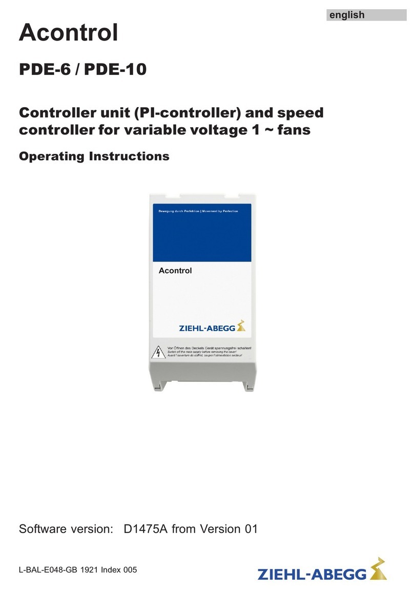
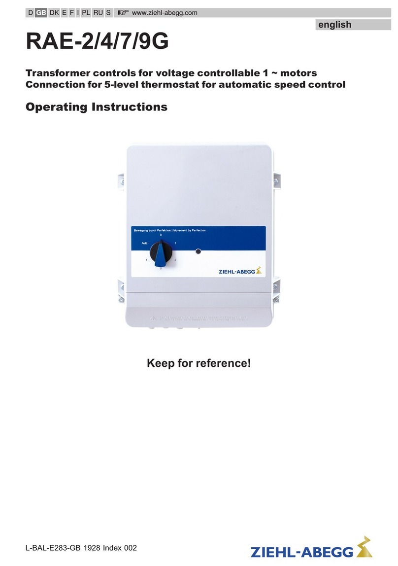
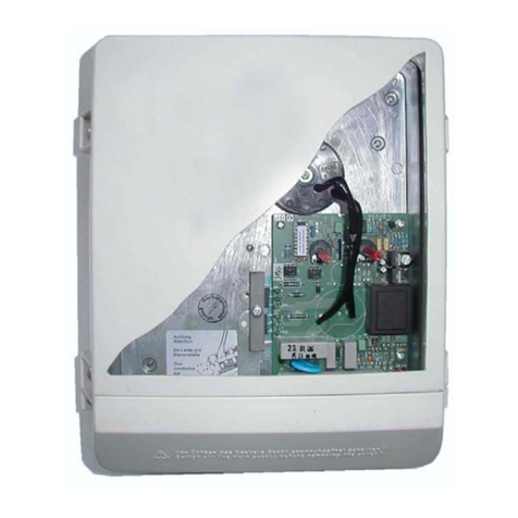
ZIEHL-ABEGG Ucontrol PXDM Series User manual

Ucontrol
Type PXDM
Universal controller for variable voltage
3~ motors
Manufacturer: ZIEHL-ABEGG AG
Heinz-Ziehl-Straße
D-74653 Künzelsau
Phone: +49 (0) 7940 16-0
Fax: +49 (0) 7940 16-504
e-mail: info@ziehl-abegg.de
internet: http://www.ziehl-abegg.de
Serial no: from Software
Year of construction: 2003

Handbook Ucontrol type-lines PXDM Date 06/04
TBL02_55-GB06/04 Part.-No. 00153239-GB
Page 2 / 105
Contents
1. General ............................................................................................................................................. 5
1.1 Copyright...............................................................................................................................................................5
1.2 Basis for device construction ................................................................................................................................5
1.3 Directions for use ..................................................................................................................................................5
1.4 Transport and storage...........................................................................................................................................6
1.5 Obligations of owner .............................................................................................................................................6
2. Safety measures .............................................................................................................................. 6
2.1 Symbols and information ......................................................................................................................................6
2.2 Electrical/electronic equipment .............................................................................................................................7
2.3 Testing in accordance with accident prevention directives...................................................................................7
2.4 Accessories, spare parts.......................................................................................................................................7
2.5 Manufacturer address, service address................................................................................................................7
3. General description ......................................................................................................................... 8
3.1 Scope of applications............................................................................................................................................8
3.2 Technical data.......................................................................................................................................................8
3.3 Versions Ucontrol..................................................................................................................................................9
4. Installation...................................................................................................................................... 10
4.1 Wall-mounting, installation in a switching cabinet...............................................................................................10
4.2 Outdoor installation of devices in housing version (IP54)...................................................................................11
4.3 Temperature influences during commissioning ..................................................................................................11
4.4 Systems with current-operated circuit-breaker ...................................................................................................11
4.5 Potential at control voltage connections .............................................................................................................12
4.6 Radiating interference / cable installation ...........................................................................................................12
4.7 Electrical installations..........................................................................................................................................12
4.8 Power decrease for ambient temperatures over 40° C (Derating) .....................................................................13
5. Electrical connections (refer also to Enclosure: Connection diagram) ..................................... 14
5.1 Mains connection ................................................................................................................................................14
5.2 Conditions for the voltage supply........................................................................................................................14
5.3 Motor connection ................................................................................................................................................14
5.4 Motor noise .........................................................................................................................................................14
5.5 Motor protection ..................................................................................................................................................15
5.6 Signal connection to analog inputs (Analog IN1, Analog IN2, ..).......................................................................15
5.7 Output voltage 0-10V (Analog OUT)...................................................................................................................15
5.8 Voltage supply for external devices (+24 V, GND) .............................................................................................15
5.9 Relay outputs (K1, K2)........................................................................................................................................15
5.10 Digital inputs (D1, D2).......................................................................................................................................15
5.11 Connection of external Terminal type AXG-1A(E) ............................................................................................16
5.12 Connection RS-485 interface for MODBUS......................................................................................................16
6. Controls and menu strukture ........................................................................................................ 17
6.1 Multipurpose LC display......................................................................................................................................17
6.2 Menu operation and menu structure..................................................................................................................18
6.3 The menu groups................................................................................................................................................19
7. Menu group Start, Info, Events ..................................................................................................... 20
7.1 Start.....................................................................................................................................................................20
7.1.1 PIN Input ....................................................................................................................................................20
7.1.2 Language ...................................................................................................................................................20

Handbook Ucontrol type-lines PXDM Date 06/04
TBL02_55-GB06/04 Part.-No. 00153239-GB
Page 3 / 105
7.1.3 Reset..........................................................................................................................................................21
7.1.4 Operating mode .........................................................................................................................................21
7.1.5 Ucontrol......................................................................................................................................................21
7.2 Info ......................................................................................................................................................................22
7.2.1 For mode speed controller 1.01.................................................................................................................22
7.2.2 For mode controller 2.01 ..,, 3.01..,, 4.01.., 5.01.., 6.01.., .........................................................................23
7.3 Events / malfunctions..........................................................................................................................................24
8. Programming................................................................................................................................. 25
8.1 Selection of the mode of operation .....................................................................................................................25
8.2 Speed controller mode 1.01................................................................................................................................27
8.2.1 Basic setting 1.01 ......................................................................................................................................27
8.2.2 Setting for operation 1.01 ..........................................................................................................................28
8.2.3 Diagram default signal and output voltage ................................................................................................28
8.2.4 Menu plan speeed controller 1.01 ............................................................................................................29
8.2.5 Factory setting for mode 1.01 (preprogrammed) and user setting ............................................................30
8.3 Temperature control mode 2.01 .. 2.05 .............................................................................................................31
8.3.1 Basic setting 2.01 .. 2.05 ...........................................................................................................................31
8.3.2 Function analog Input 2 (Analog IN 2 ) second Sensor, external Setpoint, extern manual operation ......33
8.3.3 Settings for operation modes 2.01 .. 2.05..................................................................................................34
8.3.4 Functional diagrams temperature control ..................................................................................................35
8.3.5 For mode 2.03 temperature controller with additional functions: Signal output 0-10 V.............................36
8.3.6 For mode 2.03 temperature controller with additional functions: Relay ouput for Heating or Cooling ......37
8.3.7 For mode 2.03 temperature controller with additional functions: temperature monitoring ........................38
8.3.8 Menu for temperature control 2.01 and outdoor depending 2.02 ..............................................................39
8.3.9 Menu plan temperature control with additional functions 2.03 ..................................................................39
8.3.10 Menu plan 2.04 and 2.05 temperature controls with t w o sensors comparison, average, difference ....40
8.3.11 Factory setting and user setting for modes 2.01 - 2.05 .........................................................................41
8.4 Pressure control for condensers refirgeration 3.01 .. 3.04 ................................................................................43
8.4.1 Basic setting 3.01 .. 3.04 ...........................................................................................................................43
8.4.2 Function analog Input 2 (Analog IN 2 ) second Sensor, external Setpoint, extern manual operation ......45
8.4.3 Settings for operation modes 3.01 .. 3.04..................................................................................................46
8.4.4 Functional diagram pressure control .........................................................................................................47
8.4.5 Menu for pressure control condenser, alternative input for refrigerant 3.01 and 3.02 ............................48
8.4.6 Menu pressure control dual circuit condenser, alternative input for refrigerant 3.03 .. 3.04 .....................48
8.4.7 Factory setting and user setting for modes 3.01 .. 3.04 ............................................................................49
8.5 Pressure control for ventilation systems 4.01, setpoint depending on outdoor temperature 4.02 ....................51
8.5.1 Basic setting 4.01 and 4.02 .......................................................................................................................51
8.5.2 Function analog Input 2 (Analog IN 2 ) second Sensor, external Setpoint, extern manual operation ......53
8.5.3 Settings for operation modes 4.01 and 4.02..............................................................................................54
8.5.4 Additional menu item for mode 4.02) with outside-temperature dependent target-setpoint......................55
8.5.5 Menu for pressure control airconditioning 4.01 .........................................................................................56
8.5.6 Pressure control 4.02 and setpoint depending on outdoor temperature ...................................................56
8.5.7 Factory setting and user setting for modes 4.01 - 4.02 .............................................................................57
8.6 Volume control (constant) air conditioning 5.01 , depending on outdoor temperature 5.02..............................59
8.6.1 Basic setting 5.01 and 5.02 .......................................................................................................................59
8.6.2 Function analog Input 2 (Analog IN 2 ) second Sensor, external Setpoint, extern manual operation ......61
8.6.3 Settings for operation modes 5.01 and 5.02..............................................................................................62
8.6.4 Additional menu item for mode 5.02 with outside-temperature dependent Setpoint.................................63
8.6.5 Menu for volume control airconditioning 5.01............................................................................................64
8.6.6 Menu for volume control airconditioning 5.02 and setpoint depending on outdoor temperature .............64
8.6.7 Factory setting and user setting for modes 5.01 - 5.02 .............................................................................65
8.7 Air velocity control 6.01......................................................................................................................................67
8.7.1 Basic setting 6.01 ......................................................................................................................................67
8.7.2 Function analog Input 2 (Analog IN 2 ) second Sensor, external Setpoint, extern manual operation ......68
Handbook Ucontrol type-lines PXDM Date 06/04
TBL02_55-GB06/04 Part.-No. 00153239-GB
Page 4 / 105
8.7.3 Settings for operation modes 6.01.............................................................................................................69
8.7.4 Menu for air velocity control 6.01...............................................................................................................70
8.7.5 Factory setting and user setting for modes 6.01 .......................................................................................71
9. Controller Setup............................................................................................................................. 73
9.1 Pin protection ......................................................................................................................................................73
9.2 Set protection ......................................................................................................................................................73
9.3 Save user settings in „Save User Setup“............................................................................................................74
9.4 Alarm sensors via relay ON / OFF (Alarm Sensors)..........................................................................................74
9.5 Limit.....................................................................................................................................................................75
9.6 Minimum speed cut off (operation without minimum air reate)...........................................................................76
9.7 Second Group „indirectly controlled“ or „100 %-energized“ ..............................................................................77
9.8 Reverse action of the control function (actual Value>Set = n+) .......................................................................78
9.9 Controler configuration (controller type) and controller action )..........................................................................79
10. IO Setup........................................................................................................................................ 81
10.1 Analog Output A (Analog OUT 1) .....................................................................................................................81
10.1.1 Function analog output A (Analog OUT 1) ..............................................................................................81
10.1.2 Adjustment analog output A.....................................................................................................................82
10.2 Functional overview of digital inputs D1 and D2..............................................................................................83
10.2.1 Enable ON / OFF Function 1D ..............................................................................................................84
10.2.2 External fault Function 2D .......................................................................................................................84
10.2.3 Limit ON / OFF Function 3D ....................................................................................................................85
10.2.4 Switch over E1 / E2 Function 4D............................................................................................................85
10.2.5 Set Intern 1 / Set Intern 2 or. Setpoint 1/2 Function 5D ..........................................................................86
10.2.6 Intern / Extern Function 6D .....................................................................................................................87
10.2.7 Automatic control / speed manual internal (Menu Speed maunal) Function 7D.....................................88
10.2.8 Reverse action of control function actual value>Set = n+ or actual value>Set = n- Function 8D ...........88
10.3 Inverting analog inputs E1 and E2....................................................................................................................89
10.4 Function and inverting for relay outputs K1 and K2..........................................................................................90
10.5 Network for several divices by MODBUS .........................................................................................................91
10.5.1 MODBUS - RTU (Remote terminal unit)..................................................................................................91
10.5.2 External display .......................................................................................................................................91
10.5.3 Reading and writing parameters..............................................................................................................91
11. Limits ............................................................................................................................................ 93
11.1 Limit indication depending on modulation.........................................................................................................93
11.2 Limit indication depending on setting or sensor signal ....................................................................................93
11.3 Limit indication depending on offset to Setpoint ...............................................................................................95
12. Motorsetup ................................................................................................................................... 97
12.1 Adjusting of cosjfor the connected motor .......................................................................................................97
12.2 Setting for Rampup time and Rampdown time.................................................................................................97
12.3 Suppression of speeds .....................................................................................................................................98
13. Diagnostics menu ........................................................................................................................ 99
14. Enclosure ................................................................................................................................... 101
14.1 Connection diagram........................................................................................................................................101
14.2 Connection suggestion for several motors with motor protection unit type STDT .........................................102
14.3 Dimension sheet IP54 model range..............................................................................................................102
14.4 Dimension sheet IP20 model range...............................................................................................................104
PXDM25/35(A)E ...............................................................................................................................................104

Handbook Ucontrol type-lines PXDM Date 06/04
TBL02_55-GB06/04 Part.-No. 00153239-GB
Page 5 / 105
1. General
1.1 Copyright
The copyright for these operating instructions remains with
ZIEHL-ABEGG AG, Künzelsau
These operating instructions are intended for assembly, operation, monitoring, and maintenance personnel. They contain
technical descriptions, directives, and drawings which shall be neither completely nor partially duplicated or distributed.
They shall not be used without authorisation for competition purposes or passed on to third parties.
Infringement shall result in the obligation to pay damages.
All rights reserved, especially if patents are granted or other forms of registration are submitted.
Subject to technical modifications.
Please note that these operating instructions refer to the device only and do not apply
to the entire system!
ãZIEHL-ABEGG AG, Künzelsau
1.2 Basis for device construction
The device is constructed in accordance with:
The stipulations specified in the contract, e.g. design, choice of device components, and accessory selection.
The current state of technology and the recognised safety regulations.
Nevertheless, use of the device is associated with dangers which may cause death or injury to users or third parties as
well as damage to the system and other objects.
¡The device is intended exclusively for the tasks listed in the order confirmation. Any other or extraordinary uses of the
device (unless previously agreed by contract) are considered contrary to regulations. The manufacturer is not liable for
damages resulting from incorrect use. The operating company alone bears the risk.
Observance of the procedures described in these operating instructions for assembly,
operation, and maintenance is also required for compliance with the specified use.
1.3 Directions for use
¡To allow for future developments, construction methods and technical data given are subject to alteration.
¡We do not accept any liability for possible errors or omissions in the information contained in data, illustrations or
drawings provided.
¡Before commissioning the device, ensure that you first read the information concerning assembly, adjustment,
operation, and maintenance.
¡Apart from the operating instructions and the obligatory regulations to be followed by users relating to accident
prevention, the recognised technical regulations must also be observed (safety and branch-related work as per UVV,
VBG, VDE, etc.).
¡Apart from these operating instructions, the information supplied by the manufacturer concerning components (e.g.
sensors) must also be observed.
¡These devices are potentially dangerous if they are used incorrectly by untrained personnel or are not implemented
according to their specified use.
Work at/using the devices may only be performed by personnel who are authorised to
do so owing to adequate training and qualification. In addition, personnel must also be
specifically commissioned to do so by the owner!

Handbook Ucontrol type-lines PXDM Date 06/04
TBL02_55-GB06/04 Part.-No. 00153239-GB
Page 6 / 105
1.4 Transport and storage
¡Ziehl-Abegg controllers are packed ex factory to suit the previously agreed transport method.
¡Always use the original packaging materials when transporting the controller.
¡When transporting by hand, ensure that personnel possess the strength required to lift and carry the device.
¡Avoid shocks and impacts to the device.
¡Check the packaging and controller for damage.
¡Store the controller in its original packaging in a dry and weather-proof room.
¡The device must not be exposed to extreme heat and low temperatures.
1.5 Obligations of owner
The owner is obliged to ensure that the devices are operated in perfect working order
only. It is the owner's responsibility to safeguard hazardous areas located between
ZIEHL-ABEGG devices and customer equipment!
2. Safety measures
2.1 Symbols and information
The symbols and information below warn of danger and indicate certain safety measures that must be taken.
Pay attention to this information and pass it on to other users!
Attention! Hazardous area!
Danger owing to electric current or voltage!
Important information!

Handbook Ucontrol type-lines PXDM Date 06/04
TBL02_55-GB06/04 Part.-No. 00153239-GB
Page 7 / 105
2.2 Electrical/electronic equipment
Work on electric components/modules may only be carried out by trained electricians
in accordance with electro-technical regulations (e.g. EN 60204, DIN VDE
0100/0113/0160).
The contractor or owner must also ensure that the electric systems and equipment are
operated and maintained in accordance with electro-technical regulations.
¡It is forbidden to carry out work on electrically live parts. The rating given in the enclosure for the device when open is
IP00! It is possible to inadvertently touch components carrying hazardous voltages!
¡During operation, the device must be closed or installed in a control cabinet.
¡Fuses may only be replaced by new ones and must not be repaired or bypassed.
¡Use only fuses specified in schematic diagrams.
¡The safe isolation from the supply must be checked using a two-pole voltage detector.
Any faults detected in the electric system/modules/operating equipment must be
corrected immediately. If these faults are not corrected, the device/system is potentially
very dangerous. The device/system must therefore not be operated when it is faulty.
2.3 Testing in accordance with accident prevention directives
Repair and maintenance work is often carried out by external personnel who are not aware of the special circumstances
and the resulting dangers associated with the equipment.
¡Provide this personnel with detailed information concerning the dangers that they may face during the course of their
work
¡Check that they are employing correct working procedures and intervene immediately if this is not the case
As the principal supervisor, it is your responsibility to ensure the safety of external
personnel!
2.4 Accessories, spare parts
For your own safety, use only parts, sensors, and supplementary equipment which
have been approved or recommended by ZIEHL-ABEGG. In the case of third-party
products that have not been released or recommended, or other modifications not
carried out by ZIEHL-ABEGG, it is impossible to assess whether a safety risk will arise
in connection with ZIEHL-ABEGG devices. Original ZIEHL-ABEGG parts, supplementary
equipment, and other products approved or recommended by ZIEHL-ABEGG as well as
pertaining expert consultation can be obtained from the ZIEHL-ABEGG customer
service department, tel. +49 (0) 7940 16-0. In your and our own interest, we once again
ask you to observe the information and directions given above:
OPERATIONAL SAFETY IS OF PRIME IMPORTANCE!
2.5 Manufacturer address, service address
If you have any questions concerning the use of our products or if you intend to use our products for special applications,
please contact us:
ZIEHL-ABEGG AG
Heinz-Ziehl-Straße
D-74653 Künzelsau
Phone +49 (0) 7940 16-0
Fax +49 (0) 7940 16-504
e-mail [email protected]
Internet http://www.ziehl-abegg.de

Handbook Ucontrol type-lines PXDM Date 06/04
TBL02_55-GB06/04 Part.-No. 00153239-GB
Page 8 / 105
3. General description
3.1 Scope of applications
The controlling device as described is intended for infinitely variable speed settings in voltage-regulated 3-phase motors
for driving fans and pumps.
3.2 Technical data
Type Part-No. Rated
current *
[A]
Max. line
fuse
{1}
[A]
Semi-
conductor
fuse {2}
(Part-No.)
Heat
dissipation
[W]
Weight
[kg]
Housing
protection
PXDM5 304561 2.3
PXDM5A 304564
510
Internal
FF20 A 6x32mm (00089798) approx. 40
2.4
IP54
PXDM10 304562 2.7
PXDM10A 304565 10 16 Internal
FF20 A 6x32mm (00089798) approx. 50 2.8 IP54
PXDM12 304571 3.4
PXDM12A 304572 12 16 Internal
FF30 A 10x38mm (00155987) approx.. 60 3.5 IP54
PXDM15 304563 4.75
PXDM15A 304566 15 20 Internal
FF30 A 10x38mm (00155987) approx. 85 4.8 IP54
PXDM25 305534 12.7
PXDM25A 305536
Integriert
FF50 A D02 (00091006) 12.8 IP54
PXDM25E 305549 7.2
PXDM25AE 305553
25 35
construction site
FF50 A D02 (00091006)
approx. 130
7.3
IP20
PXDM35 305535 12.9
PXDM35A 305537
Internal
FF63 A D02 (00089795) 13
IP54
PXDM35E 305550 7.4
PXDM35AE 305554
35 50
construction site
FF63 A D02 (00089795)
approx. 210
7.5 IP20
PXDM50 305565 20
PXDM50A 305567
Internal
FF100 A NH00 (00150320) 20
IP54
PXDM50E 305590 13,8
PXDM50AE 305592
50 63
construction site
FF100 A NH00 (00150320)
approx. 230
13,8
IP20
PXDM80 305566 21
PXDM80A 305568
Internal
FF160 A NH00 (00089793) 21 IP54
PXDM80E 305591 15,4
PXDM80AE 305593
80 100
construction site
FF160 A NH00 (00089793)
approx. 350
15,4 IP20
* at line voltage 400 V / 50 Hz
{1}
Max. supply side line fuse according to DIN EN 60204-1 classification VDE0113 chapter 1
{2}
Enclosed version IP54 with internal semiconductor fuse (no line protection)
Built in version for switch cabinets (IP20) semiconductor fuse installation on site recommended. Protection for damages in the case
of short-circuits.Not in the scope of supply!

Handbook Ucontrol type-lines PXDM Date 06/04
TBL02_55-GB06/04 Part.-No. 00153239-GB
Page 9 / 105
¡Line voltage 3~ 208 ... 400 V (-15 % / +10 %), 50/60 Hz
¡Stepless controlled output voltage approx. 20-100 % (line voltage)
¡Min. motor current 0.2 A for PXDM5, PXDM5 / 0.5 A for PXDM10/15/25/35...
¡Input resistance for sensor or signal set for the rotational speed:
- For 0-10 V input: Ri>100 kW
- For 4-20 mA input: Ri = 100 W
¡Voltage supply e.g. for sensors +24 V ±20 %, Imax 120 mA
¡Output (0-) 10 V, Imax 10 mA (short-circuit-proof)
¡Max. permissible ambient temperature 40° C (up to 55° C with derating)
¡Min. permissible ambient temperature 0° C (if mains voltage is not switched off up to -20°C)
¡Permissible rel. humidity 85 % no condensation
¡Interference emission EN 50081-1
¡Interference immunity EN 61000-6-2
¡Harmonics current EN 61000-3-2
The units comply with EN 61000-3-2 for a "professional unit". Up to a maximum current of
4 ampere the limits were complied without any qualification.
3.3 Versions Ucontrol
Housing version IP54 for wall mounting
¨PXDM..A internal LCD-Multifunction display with plain language text
¨PXDM.. external terminal type AXG-1A(E), for start-up and setting necessary
IP20 for switch cabinet mounting (semiconductor fuses must be installed in supply by client)
¨PXDM..AE internal LCD-Multifunction display with plain language text
¨PXDM..E external terminal type AXG-1A(E), for start-up and setting necessary

Handbook Ucontrol type-lines PXDM Date 06/04
TBL02_55-GB06/04 Part.-No. 00153239-GB
Page 10 / 105
4. Installation
4.1 Wall-mounting, installation in a switching cabinet
Please pay attention to the following points:
¡Assemble the device on a clean and stable base. Do not distort during assembly! Use the appropriate mounting
devices for proper installation of the unit!
¡Do not mount equipment on vibrating base!
¡Use the appropriate fixing equipment.
The plastic washers must be installed between the screw heads and the housing for models with mounting holes on
the inside of the housing!
¡Install the device away from transport routes. However, ensure however that the device is still easily accessible!
¡Cable ducts must remain freely accessible!
¡Protect the device from direct exposure to sunlight!
¡Consultation with the manufacturer is permissible
¡In order to ensure sufficient ventilation of the device, clearance on all sides of at least 50 mm is to be maintained to the
housing walls, switch cabinet doors, wiring ducts, etc. The same clearance applies to the installation of several
devices next to each other (Fillustration).
When installing several devices on top of each other, the danger of reciprocal heating exists. This layout is only then
permissible when the air suctioned from the upper unit does not become warmer than the permissible ambient
temperature (FTechnical specifications). I.e., a correspondingly larger clearance or thermal shielding is required.
Be sure to observe proper heat dissipation (FGeneral description: Technical data,
“Power dissipation requirements”, FInstallation: Power derating for ambient
temperatures over 40° C).
¡Installation location (for applications in agriculture)
In order to avoid damage caused by ammonia vapours (NH3), the controller shall not
be installed in the stable, but rather in an outhouse wherever possible.
min. 50 mm
Minimum space requirement

Handbook Ucontrol type-lines PXDM Date 06/04
TBL02_55-GB06/04 Part.-No. 00153239-GB
Page 11 / 105
4.2 Outdoor installation of devices in housing version (IP54)
Outdoor installation is possible under the following conditions:
¡Do not switch the controller to off at temperatures below 0°C so that the losses
from the heat dissipated in the unit can prevent condensation. In other words, do
not switch off the leads supplying the power. The internal transformer for
generating the control voltage thus remains switched on. This generates sufficient
heat.
¡The outside temperature may not fall below -20°C.
Installation must be protected from the effects of weather as much as possible,
including protection from direct sunlight (the maximum permissible ambient
temperature is 40°C, FInstallation: Power derating for ambient temperatures over
40° C).
4.3 Temperature influences during commissioning
Avoid condensation in the controller and hence functional faults attributable to condensation by storing the controller at
room temperature!
4.4 Systems with current-operated circuit-breaker
Owing to possible leakage currents occurring when the device is switched on, it is
advisable to use short-time-delayed current-operated circuit-breakers. This prevents any
triggering by mistake.
Plants without neutral conductor connection FElectrical connections: Mains connection

Handbook Ucontrol type-lines PXDM Date 06/04
TBL02_55-GB06/04 Part.-No. 00153239-GB
Page 12 / 105
4.5 Potential at control voltage connections
The control voltage connections (<50 V) relate to the joint GND potential (Exception: Relay contacts are potential free).
There is a potential separation between the control voltage connections and the earthed conductor.
It must be ensured that the maximum external voltage at the control voltage connections cannot exceed 50V
(between “GND” terminals and “PE” earthed conductor).
If necessary, a connection to the earthed conductor potential can be established, install bridge between “GND“ terminal
and the “PE“ connection (terminal for screening ).
4.6 Radiating interference / cable installation
Motor feeder cable
The applicable standard for radiating interference is EN 50081.
A unshielded motor feeder cable is required for compliance with the standard.
Sensor cable
Screened control cables must be used to prevent parasitics when the cable length is longer than 20 m or when routed in
the immediate vicinity of other cables (e.g. installed in a cable duct). When using a screened cable, the screen must be
connected to the protective conductor at one end, i.e. only at the control unit (as short and of as low an inductance as
possible!). The sensor cables may not be longer than 30 m (screened)!
4.7 Electrical installations
¡Electrical installations may only be carried out by trained specialists in accordance
with general and locally applicable regulations!
¡Dangerous electric voltages are exposed when the controller is opened. Behave
accordingly when installing the device and ensure that employees without
appropriate training cannot enter the hazardous area!
The relevant connections can be found in the circuit diagram enclosed in the enclosure
appended to these operating instructions (FEnclosure: Connection diagram)!
Only cut off necessary cable inlets respectively to the cable diameter (depending on the housing model)!
When using “WAGO” terminal strips, insert only one conductor with max. 2.5 ¨.
Cable sleeves must be used for stranded leads!
The housing must be correctly screwed into position before final
commissioning is performed and any cable ducts openings not used
(depending on the housing model) must be sealed using the supplied stoppers!

Handbook Ucontrol type-lines PXDM Date 06/04
TBL02_55-GB06/04 Part.-No. 00153239-GB
Page 13 / 105
4.8 Power decrease for ambient temperatures over 40° C (Derating)
The unit´s maximum permissible ambient temperature is 40° C, up to that temperature a load of the quoted rated current
is possible. The removal of heat in the unit due to power dissipation is dependent on the ambient temperature, so the
maximum load has to be reduced if the ambient temperature is higher than 40° C!
¨The median (measured 24 h) has to be 5° C below the max. ambient temperature.
¨Pay attention of the unit´s power dissipation and their possible effects on the ambient temperature if the unit
is mounted in a switch cabinet (FGeneral description: Technical data)!
Determinating the max. permanent current depending on the ambient temperature:
Nenn
i
K
i·D··-= )
1
04,01(
max J
=DJambient temperature – max. permissible ambient
temperature in Kelvin (K)
Example:
Max. permissible ambient temperature
(operating instructions): 40° C
Max. possible ambient temperature: 50° C
Rated current controller e.g. PXDM15: 15 A
=DJambient temperature = 50° C – 40° C = 10 K
AAK
K
i915)10
1
04,01(
max =···-=
100 %
max. Dauerstrom [A]
max. permanent current [A]
max. Umgebungstemperatur [°C]
max. ambient temperature [C°]
40 45 50 55
80 %
60 %
40 %
20 %
Regelgeräte Bemessungsstrom
Controller rated current

Handbook Ucontrol type-lines PXDM Date 06/04
TBL02_55-GB06/04 Part.-No. 00153239-GB
Page 14 / 105
5. Electrical connections (refer also to Enclosure: Connection diagram)
5.1 Mains connection
Power from the mains is connected to terminals: PE, L1, L2, L3, and N. Here, it must be strictly observed that the mains
voltage lies within the allowable tolerance specifications (FGeneral description: Technical data and nameplate affixed to
the side).
The neutral conductor connection “N” is only for the leakage current´s reduction. It is of no significance for the function of
the device. The connection is not applicable for power supply networks without a neutral conductor. Since higher leakage
currents may arise by this across the protective-cable connection “PE”, unwanted triggering by mistake may occur in
systems with FI protection circuits.
If the neutral conductor “N“ is not connected and the “PE“ connection is interrupted,
touching can result in dangerously high leakage currents. In this case, EN 50178
Section 5.3.2.1 for devices with leakage current above 3.5 mA must be observed.
5.2 Conditions for the voltage supply
The supply voltage has to correspond to DIN EN 50160 (characteristics of the voltage of public
electricity supply). Unit failures only occur in the same way as the failures of the supply
voltage, which are descriped in the norm.
In countries with a nominal frequency of 60 Hz, the above applies to 60 Hz networks.
Supply voltages that do not comply with DIN EN 50160 have to be checked seperatly.
5.3 Motor connection
The motor leads are connected to the terminals: PE, U, V, W. Several fans can be connected to the controller-the
maximum total current of all motors (maximum rated current for electronic control of the voltage) must not exceed the
current rating for the controller.
If the maximum control current for the electronic voltage control is not known, then allowance for an increase in the motor
nominal current must be made. Typical is this for 2- and 4-pole motors at approx. 25 %, for 6-pole motors at approx. 20
%, for 8- and 10-pole motors at approx. 15 % and higher pole motors at approx. 5 %.
For the control of motors made by other manufacturers (not Ziehl-Abegg), the control characteristics and the maximum
current for electronic regulation of the voltage should be enquired from the manufacturer.
It is recommended that a separate motor protection unit be foreseen for each fan .
For motors with thermistors : e.g. type U-EK230E
For motors with thermal contacts : e.g. type STDT 16 (E) or AWE-SK
(FEnclosure: Circuit suggestion for several motors with motor protection unit
type STDT)
5.4 Motor noise
Motor noise can occur when fans are controlled using electronic voltage controllers (Phase
cutting = series “P...”). Such noise can be perceived as a disturbance. This noise is relatively
low for fast-running fans where the noise from the air is high. The noise from motors in slower-
running fans where the noise from the air is less, can be dominated by resonance in the lower
speed ranges.
For systems where noise is critical, we recommend using our Fcontrol series frequency
converters with integrated sinusoidal filter

Handbook Ucontrol type-lines PXDM Date 06/04
TBL02_55-GB06/04 Part.-No. 00153239-GB
Page 15 / 105
5.5 Motor protection
¨The motor can be protected by connecting the thermal contacts or PTC resistor.
¡When several motors are connected ensure that the thermal contacts or PTC
resistors are always connected in series. A maximum of six individual thermistors
(DIN 44081 or DIN 44082) may be connected in series to a single device. Depending
on the motor type, at least two or three individual sensors are built in.
¡Monitoring of motors in “Ex“ zones is not permissible. For systems of this type, an
additional posistor tripping unit is required, with disconnection via a separate motor
protection circuit.
The unit switches off when a connected thermal contact or PTC resistor has tripped the circuit (interruption between both
TK terminals). The unit then remains switched off. A programmed fault-indicating relay is triggering,the internal red LED
for motor fault illuminates, the green LED for operating goes off. The unit starts up again once the drive has cooled down
by switching the mains voltage OFF and then ON again or by enable ON/OFF (FIO Setup).
Display during motor fault alternating to the actual value
¡An outside voltage may never be connected to the terminals “TK”!
¡The internal motor protection does not function if a bypass circuit has been realised.
In this case and as well as other precautions, an additional thermal contact
protective device is necessary.
5.6 Signal connection to analog inputs (Analog IN1, Analog IN2, ..)
The unit has 2-analog inputs
Input 1 (Analog IN1) terminals „E1“ and „GND“
Input 2 (Analog IN2) terminals „E2“ and „GND“
Ensure correct polarity when connecting; a 24 V DC power supply is integrated for sensors. For sensors in two-wire-
technology (4-20 mA signal), the connection is made on the +24 V and „E1“ or „E2“ terminals (the GND terminal is
omitted).
The connection is independent of the programmed operating mode and from the sensor signal employed (FPresets of
the selected operating mode).
5.7 Output voltage 0-10V (Analog OUT)
The 0-10 V analog outputs can be allocated with various functions
(FIO Setup: Analog output A). Connection to terminal „A“ - „GND“ = Analog OUT (Imax 10 mA)
5.8 Voltage supply for external devices (+24 V, GND)
A voltage supply is integrated for external devices, e.g., for a sensor.
Terminal +24 V Output voltage tolerance ±20 %.
Max. load current 120 mA (for connection to an external AXG terminal minus ca. 50 mA)
During an overload or short-circuit (24 V «GND), the control voltage (and thus the controller) is disconnected (Multifuse).
Automatic start after elimination of the cause of error
5.9 Relay outputs (K1, K2)
Various functions can be allocated to the relay outputs K1 and K2
(FIO Setup: Function and inversion of the relay outputs). Max. contact load 5A / 250 V AC
Connection of the floating contacts of relay K1 to the terminals 11, 14, 12
Connection of the floating contacts of relay K2 to the terminals 21, 24, 22
5.10 Digital inputs (D1, D2)
Various functions can be allocated to the digital inputs D1 and D2
(FIO Setup: Functions summary of the digital inputs).
Activation via floating contacts (a low voltage of ca. 24 V DC is connected).
Never apply external voltage to the digital inputs!

Handbook Ucontrol type-lines PXDM Date 06/04
TBL02_55-GB06/04 Part.-No. 00153239-GB
Page 16 / 105
5.11 Connection of external Terminal type AXG-1A(E)
An external terminal is required for starting-up and setting-up versions that do not have an integrated terminal (model
series PXDM..(E)).
Model AXG-1A, Part-No. 349006 for manual operation
Model AXG1AE, Part-No. 349008 for panel mounting
The connection is made via a 4-strand line, e.g., telephone flex (e.g. J-Y (St) Y 2x2x0.6 (or similar)),
maximum line length ca. 250 m.
- Voltage supply: Terminal 24 V, GND, (Imax for terminal ca. 50 mA)
- Signal D+ and D- (RS 485)
The data connector spring-loaded contact is suitable for solid conductors of up to 0.5 mm2 cross-section or 0.8 mm
diameter. The stripped lead makes contact by itself upon insertion. The orange colored latch only needs to be pushed in
the case of smaller cross-sections or when detaching the connections.
5.12 Connection RS-485 interface for MODBUS
The device comes equipped via a RS-485 interface for networking via a MODBUS. The data connection lead is
connected to D+, D- and GND.
When using an external AXG.. terminal, the interface is assigned and can not be employed for anything else.
You must ensure correct connection; i.e. „D+“ must also be connected on the following devices to
„D+“. The same applies to „D-“.
In addition, a GND connection must be established, as dissimilar potential (over 10 V !) will lead to the
destruction of the RS-485 interface (e.g. lightning).
The data line must be conducted from one device into the next. To do this, two connectors are
available in each device. No other type of wiring is allowed.
Always use only two wires of one lead for the connection.
When using telephone flex with four cable cores, we recommend the following allocation:
“D+“ = red “D-“ = black “GND“ = white
Examples:
A maximum of 247 network users can be connected to the data bus
Ucontrol
MODBUS
Ucontrol
MODBUS

Handbook Ucontrol type-lines PXDM Date 06/04
TBL02_55-GB06/04 Part.-No. 00153239-GB
Page 17 / 105
6. Controls and menu strukture
1 Multipurpose display
2 P-key (program key, open menu)
3 arrow -down-key (Menu down, reduce value)
4 arrow-up-key (Menu up, increase value)
5 ESC-key combination: arrow-down-key + arrow-up-key (Escape, leave menu)
6.1 Multipurpose LC display
The multipurpose LC display is specifically matched to this unit. If offers an optimum overview during adjustment and
control of the device. The display is inverted; i.e., the symbols and characters are luminously displayed with the amber-
colored background lighting. Through that, the display is always easily legible even during large distances and in dark
environments. In addition to the texts and numerical values, symbols are present that constantly display the device’s most
important operating conditions.
Application of the symbols is dependent on the type of device and the operating mode selected.
1 Moon-Symbol (set point 1 / 2, e.g. for day / night operation)
2 Arrow 1-Symbol (not in use)
3 Alarm-Symbol (fault indication)
4 Arrow 2-Symbol (not in use)
5 Fire-Symbol (heating operatioin)
6 Arrow 3-Symbol (not in use)
7 Antenna-Symbol (Remote-Control aktiv)
8 Arrow 4-Symbol (not in use)
9 STOP-Symbol (enable)
10 Bargraph (intern control output)
11 Text line 3 figures (Anzeige Einheit, etc.)
12 Text line 16 figures (Anzeige Menütexte, etc.)
13 Numeric display 5 digit (display values, time, etc.)
Display after turning on the mains voltage
Example for mode 1.01
After the keys have not been pushed for ca. 15 minutes, the device switches to the display of the current modulation
(when being operated as a speed controller) or during operative modes as a controller for control of currently active
sensor signals (actual value).
Switch-over between Start and Fanlevel or actual value with the key shortcut for Escape (Esc = ↑+ ↓).
1
5
43
2
Automatically after approx. 15 Min.
+
= Esc
GHI
0123456789ABCDEF
STOP
1
12
11
13
2345678 9 10

Handbook Ucontrol type-lines PXDM Date 06/04
TBL02_55-GB06/04 Part.-No. 00153239-GB
Page 18 / 105
6.2 Menu operation and menu structure
After switching on the device or mains supply, the Start menu group appears in the display. One reaches the menu items
of this menu group by pushing the “P“ key. General settings and queries can be undertaken there. The desired
C o u n t r y l a n g u a g e, e.g., can be set for initial start-up operation here.
One moves up and down within the menu group using the arrow keys. One returns to the menu group using the ESC (↑+
↓) shortcut keys (push the keys simultaneously). Selection of the menu group to the right through the down key, to the left
through the up key.
The menu groups consist of one area for the user (user menu) and one area for installation (service). The service area
can be protected against unauthorized access by using a PIN (Personal Identification Number). In order to simplify the
initial start-up operation, the service level is enabled at first (i.e., not protected by the PIN 0010, see Controller Setup, PIN
protection = OFF). If PIN protection is activated (ON), the service menu remains enabled after input of PIN 0010 as long
as one is pressing keys. If no keys are pressed for ca. 15 minutes, the PIN is automatically erased, i.e. the service level is
blocked.
After installation of the device has been carried out, PIN protection should be activated!
The menu and its menu items are independent of the type of operating mode set. Here is a partial portrayal of the menus
for the factory mode of operation 1.01 speed controller.
PIN Protection OFF
PIN protection ON PIN 0010 necessary
User level Service level

Handbook Ucontrol type-lines PXDM Date 06/04
TBL02_55-GB06/04 Part.-No. 00153239-GB
Page 19 / 105
6.3 The menu groups
General functions
PIN Input for loading factory- and usersetting, open service menu, setting menu language,
Reset after fault, Query of the device software version
Display for modulation, settings, actal values, status for minimum speed cut off.
(settings are not possible in this group of menus)
Setting for operation
settings, Pband, Min. and Max. speed, manual operation,
Display and query of events and malfunctions
Base setup (Installation)
Selection mode of operation, Configuration of analog signal- and sensor
inputs
Service level User level
Controller Setup
Protection of the settings, message during sensor malfunctions ON /
OFF
Limitation of modulation, minimum speed cut off ON / OFF, group
control, reverse action of control function (Heating / Cooling), controller
configuration (P, PID)
IO Setup
Function and Inverting analog outputs, for digital inputs, for relay
outputs. Inverting of analog inputs. Setting Bus address for
network
A
djustable limit indication for:
modulation, analog input signal ,deviation between actual and
target
Motor Setup
setting for cos Phi, ramp up time and ramp down time,
suppression of speeds
Diagnostics
display of the internal temperature, height of the input
signal, status of digital inputs and relay outputs, line
frequency

Handbook Ucontrol type-lines PXDM Date 06/04
TBL02_55-GB06/04 Part.-No. 00153239-GB
Page 20 / 105
7. Menu group Start, Info, Events
7.1 Start
7.1.1 PIN Input
The service menu for the installation can be protected against unintentional changes by a pin code
With further pin codes putting back to pre-setting is possible.
Example for PIN input 0010 for opening service menu (if PIN-protection activatet FController
Setup).
Inform before input the respective pin about effects (Fexplanation).
PIN Function description
0010 opening service menu, if PIN-protection activated (FPIN protection)
1234 opening “setting“, if “set protection“ ON (Fset protection)
9090 restore user setting (FSave user setup)
9091 Save user setting (corresponds function Save user setup ON) (FSave user setup)
9095 Restore factory setting = delivery status (Frespective mode)
7.1.2 Language
Menu language by the factory set to English. In this menu different national languages can be selected
(GB = English, D = Deutsch, ...).
Example for re-programming English to German
↓P ↑ESC
↓P ↑ESC
↓↑
3x 2x
This manual suits for next models
24
Table of contents
Other ZIEHL-ABEGG Controllers manuals

ZIEHL-ABEGG
ZIEHL-ABEGG Dcontrol PKDM6 User manual

ZIEHL-ABEGG
ZIEHL-ABEGG Acontrol PSET6 User manual

ZIEHL-ABEGG
ZIEHL-ABEGG R-ET6KTG User manual

ZIEHL-ABEGG
ZIEHL-ABEGG Acontrol PDE-6 User manual

ZIEHL-ABEGG
ZIEHL-ABEGG R-DK Series User manual

ZIEHL-ABEGG
ZIEHL-ABEGG Econtrol EXDM User manual

ZIEHL-ABEGG
ZIEHL-ABEGG PAE10E-M User manual

ZIEHL-ABEGG
ZIEHL-ABEGG Acontrol PKE-6 User manual

ZIEHL-ABEGG
ZIEHL-ABEGG R-E-0.5E User manual

ZIEHL-ABEGG
ZIEHL-ABEGG RAE-2G User manual