Muirhead 3565 User manual

PRODUCT MANUAL
ENGINE PROTECTION SYSTEM
6-FUNCTION TO SUIT WATER COOLED ENGINES
Part No. 3565

2| 28
M0160.docx | Rev 1.3 | Modified on 19/05/2020 | © Remote Control Technologies Pty Ltd
LEGAL NOTICE
1. You acknowledge that this document is protected under copyright law and Remote Control Technologies Pty Ltd or its related bodies
corporate (“RCT”) owns the copyright in this document or otherwise have permission or licence from the relevant owner to use certain
specific works.
2. You must not make any changes, amendments, variations, alterations or modifications to the document.
3. You must not reproduce this document in any form or by any means, or to make copies of this document without RCT’s prior written
consent.
4. The contents in this document constitute confidential information of RCT. You must not circulate, distribute or otherwise allow the
document to be available in the public domain, or to disclose or share the document with any third party, without RCT’s prior written
consent.
5. RCT provides the document to you on an “as is” basis. RCT is not required to provide any updates to this version of the document.
RCT may make any change, amendment or modification to the contents in this document without notice to you.
6. RCT takes a best endeavour basis to ensure that the contents in this document are accurate, complete and reliable. RCT does not
warrant that the document will continue to be reliable, relevant, accurate or complete due to RCT’s continuous efforts in product
development, innovation and technology.
7. Any trademarks used in this document belongs to RCT or is used under a licence. The trademarks are not to be used for any
purposes, without RCT’s prior written consent.
8. Any illustrations used in this document are for illustration purposes only. Illustrations are intended as aids to facilitate your
understanding of the subject matter or issue.
9. RCT disclaims all liability, loss or damage that you suffer as a result of your reliance on this document.
10. By your conduct of using or reading this document, you agree to and accept the terms in this notice.

M0160.docx | Rev 1.3 | Last modified 19/05/2020 | © Remote Control Technologies Pty Ltd
3| 28
Contents
⚠Caution
Consult the specifications data sheet on page 23 prior to installing the product.—incorrect fitment will void the
manufacturer’s warranty.
General Safety Warnings 6
Personal Safety 6
Machine 6
Product 6
Product Overview 7
Features and Functions 7
Operation and Use 8
Control Unit 8
Wiring Connections 8
Inputs 9
−Function 6 9
Outputs 10
−Alarm Control Output 10
−Idle Control 10
−Engine Control (ETR) 10
Installation Guide 11
Control Unit 11
Audible Alarm 11
Coolant Level Sensor – Function 1 12
Engine Oil Pressure Switch – Function 2 12
Coolant Temperature Switch – Function 3 13
Oil/Fuel Level Switch – Function 4 13
Coolant Flow Switch – Function 5 14
Converter Oil Temperature – Function 6 14
Engine Protection System Labelling 15
Alert Function Identification Labels 16
Typical Engine Protection System Schematic to suit 6-Function Water-cooled Engine (236s) 17
Calibration 18
Service Information 18
Service Schedule 18
Service Procedure 18
−Coolant Level Sensor 18
−Engine Oil Pressure Switch 18
−Engine Temperature Switch 18
−Oil/Fuel Level Switch 18
−Coolant Flow Switch 19
−Convertor Oil Temperature Switch 19
Test Procedure 19
−Control Unit 19
−Coolant Level Sensor 20
−Engine Oil Pressure Switch 20
−Engine Temperature Switch 20
−Oil/Fuel Level Switch 20
−Coolant Flow Switch 20
−Convertor Oil Temperature Switch 20

4| 28
M0160.docx | Rev 1.3 | Modified on 19/05/2020 | © Remote Control Technologies Pty Ltd
Parts List 21
Decals supplied with the Product 21
Wiring Loom to suit 3565 Control Unit 21
Coolant Level Sensors 21
Pressure Switches to suit Engine Oil Pressure Applications 21
Pressure Switches to suit Temperature Monitoring Applications 22
Flow Switches to suit Coolant Flow Applications 22
Oil/Fuel Level Switches to suit the Oil Level Monitoring Applications. 22
Alarms to suit the Warning Alert Function of the Control Unit. 22
Technical Specifications 23
Additional Specifications 23
−Power Supply 23
−Inputs 23
−Outputs 23
Compliance and Standards 24
Troubleshooting 24
Glossary 25
Warranty 26
Appendix 27
ETR Idle Timer / EPS / Fire Control Unit Diagram (478i) 27

M0160.docx | Rev 1.3 | Last modified 19/05/2020 | © Remote Control Technologies Pty Ltd
5| 28
Table of Figures
Figure 1 Muirhead®Engine Protection System, part number 3565.................................................................. 7
Figure 2 EPS control unit external view............................................................................................................ 8
Figure 3 EPS label, water cooled ................................................................................................................... 15
Figure 4 Drawing 236s – EPS protection system water-cooled external wiring diagram............................... 17
Figure 5 Drawing 478i – ETR idle timer/EPS/fire controller external wiring diagram..................................... 27

6| 28
M0160.docx | Rev 1.3 | Modified on 19/05/2020 | © Remote Control Technologies Pty Ltd
General Safety Warnings
Personal Safety
■Everyone is responsible for safety.
■The installer/service personnel should be trained and authorized to complete the required work.
■Ensure that the machine is safely isolated during installation and testing to protect all personnel.
■Complete all required risk assessments and job safety analysis (JSA) before commencing work.
■Observe all site-specific and machine OEM procedures regarding the following:
– working at heights
– working in heat
– working in confined spaces
– all other site-specific occupational health and safety (OH&S) procedures
Machine
■Carry out all pre-start operations as per site and machine OEM procedures.
■Ensure the machine is safely isolated during installation and testing to protect the machine and other
equipment in the area.
■Do not operate any machine with a known fault and report all findings to the supervisor in writing.
■Test and operate machine as per machine OEM and site procedures.
■Read and understand machine and site-specific operational and testing instructions.
Product
Before applying power to the equipment, the user/repairer/installer must read all product instructions. If in
doubt, seek assistance.
■Ensure electrical connections are made as per RCT’s recommendations. Test circuits prior to connecting
power to any part.
■The equipment has no user-serviceable parts inside. Return the unit to RCT for repairs.
■Retain product and installation instructions for future use.
■Ensure that RCT’s recommended service procedures are included in the machine’s service routine.
■Observe all machine, site and RCT product warnings.
■Follow all machine, site and RCT product operating procedures at all time.
The application of safety should not be limited to the above recommendations.

M0160.docx | Rev 1.3 | Last modified 19/05/2020 | © Remote Control Technologies Pty Ltd
7| 28
Product Overview
Figure 1Muirhead®Engine Protection System, part number 3565
The Muirhead®Engine Protection system (EPS), part number 3565, is designed to monitor almost any alarm
condition on virtually any machine.
This system has been designed to monitor six inputs including an AC input for detecting coolant loss and three
digital outputs. The system continuously monitors six areas of protection and alerts the operator of abnormal
engine conditions.
With no mechanical parts, the EPS control unit is extremely reliable, easy to install and simple to use. Every
EPS control unit can be customised to monitor known problems and functions commonly associated with
equipment failure.
Note
Additional looms, fittings, switches, lights, and audible alarm maybe required to perform a complete installation.
Features and Functions
Multi-voltage (8 to 32 volts)
Alarm only, return to idle/shutdown modes
System test function
Custom fault indicator labelling
Configurable inputs
Reduces downtime
Substantially reduces the risk of engine failure
Simple installation
Audio/visual indicators
Six inputs and three outputs
Individual fault indicators
Compact and robust control panel design
Extends machine life
Multiple applications
IP65 enclosure

8| 28
M0160.docx | Rev 1.3 | Modified on 19/05/2020 | © Remote Control Technologies Pty Ltd
Operation and Use
Control Unit
Electronic circuitry within the EPS control unit checks the state of the switches and sensors, and then activates
the corresponding alert indicator and control outputs when an alarm condition is sensed.
The EPS label displays the alert indicator or function that has faulted. A test switch on the front of the EPS
control unit allows the operator to simulate a fault and test the complete system.
A connector with 12 contacts on the rear of the EPS control unit facilitates the necessary wiring for the inputs
and outputs.
Figure 2EPS control unit external view
Wiring Connections
No. Function Type
1 +8 Vdc to +32 Vdc Ignition supply
2 −0 Vdc ground Ground
3 Output 1 Alarm control
4 Output 2 Idle control
5 Output 3 Energised to run control (ETR)
6 Input Start input
7 Function 1 Ac circuit/switch input
8 Function 2 Switch input
9 Function 3 Switch input
10 Function 4 Switch input
11 Function 5 Switch input
12 Function 6 Ac circuit/switch input
Alert Indicators
Test Switch
12-pin Connector

M0160.docx | Rev 1.3 | Last modified 19/05/2020 | © Remote Control Technologies Pty Ltd
9| 28
Inputs
The following input functions show the factory defaults with all inputs and outputs being configurable. Refer to
document number P0021 for advanced programming information. Contact your local RCT branch or distributor
for a copy of the document or for more information.
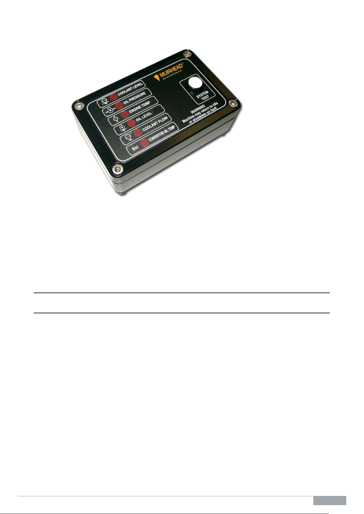
Function 1
This input is configured to have a five-second delay prior to pulsing the alert indicator and activating the alarm.
After a further 10 seconds, the alert indicator will come on solid, the alarm will remain on and activate the idle
and ETR control circuits. This circuit activates when the circuit changes state and becomes open. This input
is specifically designed for coolant level detection. If this function is not required, pin 7 must be connected to
ground.
Note: This function uses an AC (alternating current) circuit. This reduces electrolysis and corrosion of the
coolant level sensor. This will help to keep the probe in good working order.
Function 2
This input is configured to have a one-second delay prior to activating the corresponding alert indicator,
external audible alarm, idle and ETR control circuits. This circuit activates when the circuit changes state and
becomes open. If this function is not required, pin 8 must be connected to ground.
Typical use: Low engine oil pressure
Function 3
This input is configured to have a one-second delay prior to activating the corresponding alert indicator,
external audible alarm, idle and ETR control circuits. This circuit activates when the circuit changes state and
becomes open. If this function is not required, pin 9 must be connected to ground.
Typical use: High engine temperature
Function 4
This input is configured to have a one-second delay prior to activating the corresponding alert indicator,
external audible alarm, idle and ETR control circuits. This circuit activates when the circuit changes state and
becomes open. If this function is not required, pin 10 must be connected to ground.
Typical use: Low engine oil level
Function 5
This input is configured to have a one-second delay prior to activating its corresponding alert indicator, external
audible alarm, idle and ETR control circuits. This circuit activates when the circuit changes state and becomes
open. If this function is not required, pin 11 must be connected to ground.
Typical use: Coolant flow
Function 6
This input is configured to have a one-second delay prior to activating its corresponding alert indicator, external
audible alarm, idle and ETR control circuits. This circuit activates when the circuit changes state and becomes
open. If this function is not required, pin 12 must be connected to ground.
Typical use: Convertor oil temperature

10 | 28
M0160.docx | Rev 1.3 | Modified on 19/05/2020 | © Remote Control Technologies Pty Ltd
Outputs
Alarm Control Output
This circuit is activated as soon as an alert indicator is active. This output remains active until the EPS control
unit has no alert indicator active or the key is switched off. This output is disabled until a start signal is sensed.
This allows servicing to be carried out with the key on without the alarm sounding.
Idle Control
This circuit works as a direct opposite to the alarm control output. It switches off when the alarm control output
is active. This output is used in conjunction with other control systems that return the engine to idle when an
alert indicator is activated. If return to idle is not needed, this circuit should not be connected.
This circuit overrides for 10 seconds after start is activated.
Engine Control (ETR)
This circuit works in a similar way to the idle control output; however, it has a 0 to 40-second adjustable time
delay. This time delay is factory set to 10 seconds, allowing the machine to run for 10 seconds after an alert
indicator has been activated. This circuit is an energised to run output. This output also incorporates an
automatic system override circuit which allows the EPS control unit to override the engine oil pressure switch
allowing the engine to be started. If shutdown is not needed, this circuit should not be connected.
⚠Warning
When an alert indicator is active, special care should be taken to access safety considerations which may arise
from shutting the machine down.
1. Will the machine be left uncontrollably, as shutdown affects the braking and steering of most machines?
2. Can the machine be parked in a safe environment?

M0160.docx | Rev 1.3 | Last modified 19/05/2020 | © Remote Control Technologies Pty Ltd
11 | 28
Installation Guide
Note
If the EPS system is installed in conjunction with an idle timer and/or a fire status control unit, it is imperative
that the units are installed in the correct order. Failure to do so may result in the machine not shutting down
correctly.
Refer to the appendix at the end of this manual for the correct sequence.
Control Unit
1. The recommended location for the control unit is in the operator’s cabin in clear view and within easy reach
of the operator. Proximity to the operator is important as the control unit incorporates a system test
switch/circuitry that allows service personnel and/or operators to test the system.
2. Drill two 8 mm diameter holes with the hole centres being 100 mm apart to suit the M8*30 hex screws that
bolt to the control unit mounting bracket. Careful consideration should be given to the location of these
holes before drilling to ensure adequate accessibility to the electrical connection located on the rear of the
control unit.
3. Refer to the wiring table below and the wiring diagram in this manual to wire up the control unit. It is
recommended that the wiring loom be installed alongside the OEM engine wiring ensuring that it is secured
at regular intervals; this will provide protection from heat and abrasion, and any other excess damage that
may occur with extended machine operation. When securing the loom to the OEM engine wiring, ensure
that the loom is away from moving machine parts which could lead to loom damage.
4. Install the sensors/ switches (see below for more detail). All sensors/ switches should be installed using a
suitable thread sealant.
Options
If a Muirhead®Idle Timer is fitted, the machine will return to idle at once.
If a Muirhead®Shutdown Control unit is fitted, the machine will return to idle for the specified time and then
shut down.
Notes
Perform a system test using the test procedure in the Calibration section in this manual.
For information on testing individual functions and/or parts of the EPS system, refer to the additional testing
information in this manual.
Audible Alarm
There are three ways of mounting the audible warning alarm.
1. Through instrument panel (via a 29 mm hole)
2. Via an optional mounting bracket (part number 9655)
3. Under the instrument panel (cable tied to loom)

12 | 28
M0160.docx | Rev 1.3 | Modified on 19/05/2020 | © Remote Control Technologies Pty Ltd
Coolant Level Sensor – Function 1
It is recommended that the coolant level sensor be installed in the radiator tank (refer to the details below).
Ensure there is sufficient clearance within the radiator to accommodate the length of the coolant. Drill the
required hole size in the tank and tap to the required thread size as specified below. Always clean debris away
and remove any foreign objects before installing the probe. Fit the coolant level sensor and pressure test, this
can be achieved by running the engine until normal operating temperature has been reached.
Engine Oil Pressure Switch – Function 2
The engine oil pressure switch should be in a suitable oil gallery access port. Use the original equipment
manufacturer (OEM) oil pressure switch as a guide for location. Fit the oil pressure switch using thread sealant,
being careful not to over tighten.
Note
T-pieces are available in most thread types to enable both the OEM and Muirhead®Oil Pressure Switches to
be installed into the original port.
Part No. 0018
12 PSI
Normally Open
Thread: 1/8 NPT
Part No. 3074
8 PSI
Normally Open
Thread: 1/8 NPT
Part No. 8725
9 PSI
Normally Open
Thread: 1/8 NPT
Part No. 9976
12 PSI
Normally Open
Thread: 9/16 UNO
Part No. 3429
16 PSI
Normally Open
Thread: 1/8 NPT
Part No. 3430
9 PSI / 62 kPa
Normally Open
Thread: 1/8 NPT
Radiator
Installation Example
Probe Position
Optimum probe level is ⅓
up from the bottom of the
top hose hole.
Part No. 2006
Thread: 1/8 NPT
Nylon
Tapping drill: 21/64”
Probe length: 30 mm
Part No. 2887
Thread: 1/4 NPT Nylon
Tapping drill: 7/16”
Probe length: 72 mm
Note: Brass weld
collar included
Part No. 2205
Thread: 1/4 NPT Brass
Probe length: 60 mm
Tapping drill: 7/16”

M0160.docx | Rev 1.3 | Last modified 19/05/2020 | © Remote Control Technologies Pty Ltd
13 | 28
Coolant Temperature Switch – Function 3
The coolant temperature switch should be installed on the engine side of the thermostat control. It is imperative
that the switch sensing area (bulb) be immersed in coolant. Install the switch using thread sealant.
Note
Care should be taken when selecting a mounting port to allow sufficient depth for the bulb.
Part No. 1764
212°F / 100°C
Normally Closed
Thread: 3/8 NPT
Part No. 1765
220 °F / 104 °C
Normally Closed
Thread: 3/8 NPT
Part No. 1766
230 °F / 110 °C
Normally Closed
Thread: 3/8 NPT
Part No. 8491
Heavy Duty Temp
Switch
225 °F / 107 °C
Normally Closed
Thread: 3/8 UNO
Oil/Fuel Level Switch – Function 4
The oil/fuel level switch is a capacitive type switch with a ¼ NPT mounting thread and used to monitor levels
in tanks and reservoirs. The switch should be installed at the low level mark which is specified by the OEM.
Ensure there is sufficient clearance within the tank so as not to interfere with the switch installation. Install
switch using thread sealant.
Note: Care should be taken when selecting a mounting position as the maximum allowable ambient
temperature for the switch is 100 °C. Also note that the oil/fuel level switch incorporates a three-second alarm
delay.
Part No. 3072
Normally Open
Thread: 1/4 NPT brass
Tapping drill: 7/16”

14 | 28
M0160.docx | Rev 1.3 | Modified on 19/05/2020 | © Remote Control Technologies Pty Ltd
Coolant Flow Switch – Function 5
The coolant flow switch monitors the coolant flow in the engine while it’s operating; the coolant flow switch is
installed as specified by the OEM.
The switch is suitable for the following Caterpillar engines:
■3306, 3406, 3408, 3508, 3512, and 3516
Note: If being installed on different engine models, the installer is required to supply a suitable mounting.
Part No. 6041
Normally Open
56 mm Paddle
Converter Oil Temperature – Function 6
Installation
The convertor oil temperature switch is to be installed in conjunction with the OEM convertor oil temperature
switch. It is imperative that the switch sensing area (bulb) be immersed in oil. Install the switch using thread
sealant.
Note: Care should be taken when selecting a mounting port to allow sufficient depth for the bulb.
Part No. 7166
265 °F / 129 °C
Normally Closed
Thread: 3/8 NPT
Part No. 1359
266 °F / 130 °C
Normally Open
Thread: 3/8 NPT
Part No. 1768
275 °F / 135 °C
Normally Closed
Thread: 3/8 NPT
Part No. 7167
280 °F / 138 °C
Normally Closed
Thread: 3/8 NPT
Part No. 7168
300 °F / 149 °C
Normally Closed
Thread: 3/8 NPT

M0160.docx | Rev 1.3 | Last modified 19/05/2020 | © Remote Control Technologies Pty Ltd
15 | 28
Engine Protection System Labelling
Water-Cooled
Figure 3EPS label, water cooled
There are a wide range of decals available and also blank decals which can be used when not all six functions
are required.
The engine protection system incorporates a simple but effective labelling system that can be customised to
suit individual needs.
The construction of the label is a simple process.
1. Select the correct decal that is required for the application.
2. Remove the adhesive backing from the decal and place in the correct clear insert on the main label. Make
sure the decal is aligned correctly (as shown in the above diagram).
3. Use a plastic card or similar tool to carefully push any air bubbles that form out to the edges of the label.
4. Once all the decals that are required have been placed in their correct clear inserts on the main label,
remove the adhesive backing from the main label and fit it onto the engine protection control enclosure.
5. Remove all air bubbles and clean the label.
The labelling process is now complete.
SYSTEM
TEST
WARNING
Machine may return to idle
or shutdown on fault
PROTECTION SYSTEMS
OIL LEVEL
ENGINE TEMP
OIL PRESSURE
COOLANT FLOW
FUNCTION 1
Typically used for coolant level monitoring
FUNCTION 2
Typically used for engine oil pressure monitoring
FUNCTION 3
Typically used for engine temperature monitoring
FUNCTION 4
Typically used for oil level monitoring
FUNCTION 5
Typically used for coolant flow monitoring
FUNCTION 6
Typically used for convertor oil temperature monitoring

16 | 28
M0160.docx | Rev 1.3 | Modified on 19/05/2020 | © Remote Control Technologies Pty Ltd
Alert Function Identification Labels
Part No, Label Part No. Label
5636 6143
0427 1526
1372 5630
5629
5635
0426 5634
0437 5637
0428 1413
0442 4352
0453 5638
0486 5633
3465 4350
3144 5631
5785 5632
5780 4348
5782 1411
5784 4349
5779 5628
5781 1417
5783 8424
5778 1368

M0160.docx | Rev 1.3 | Last modified 19/05/2020 | © Remote Control Technologies Pty Ltd
17 | 28
Typical Engine Protection System Schematic to suit 6-Function Water-cooled Engine
(236s)
Figure 4Drawing 236s – EPS protection system water-cooled external wiring diagram
1
2
3
4
5
6
7
8
9
10
11
12
ENGINE PROTECTION
SYSTEM CONTROL
T°
BK-4
YL-4
N/C ENGINE
TEMPERATURE
SWITCH
P
OIL
PRESSURE
SWITCH
N/O
BK-4
PK-4
BU/WH-4
L
COOLANT
LEVEL
PROBE
GROUND VIA
COOLANT
TO TANK
RD-4
GY-4
BK-4
C
A
B
OIL
LEVEL
SWITCH
+
-
FAULT
ALARM
CAUTION
OUTPUT CURRENT
RATING
6AMP MAX
BK-4
BN-4 +
-
NOTE 1
THIS IS A TYPICAL ENGINE
PROTECTION SYSTEM SCHEMATIC
ILLUSTRATING ALL OUTPUT AND
INPUTS. THIS SHOULD ONLY BE USED
AS A GUIDE. DIFFERENT MACHINES
REQUIRE DIFFERENT COMPONENTS.
FOR MORE INFORMATION PLEASE
CONTACT THE MANUFACTURER.
IDLE CONTROL
SOLENOID
CAUTION
OUTPUT CURRENT
RATING
6AMP MAX
!
BK-4
YL/BU-4 +
-
ETR RUN
SOLENOID
CAUTION
OUTPUT CURRENT
RATING
6AMP MAX
!
8 - 30VDC
PROTECTED
SUPPLY
(RECOMMENDED
10AMP
PROTECTION)
TO
START
TERMINAL
AT
KEY
SWITCH
MACHINE
(FRAME)
GROUND
NOTE 2
IF NOT ALL FUNCTIONS ARE
REQUIRED, A BLANK IS PLACED ON
THE UNUSED FUNCTION AND THE
CORRESPONDING INPUT WIRE MUST
BE CONNECTED TO GROUND.
+
S
-
ENGINE TEMP
OIL PRESSURE
COOLANT LEVEL
OIL LEVEL
ALARM
IDLE CONTROL
ETR CONTROL
START INPUT
COOLANT FLOW
CONVERTOR TEMP
8 - 30V SUPPLY
GROUND
YL-4
PK-4
BU/WH-4
GY-4
GN-4
BN-4
YL/BU-4
PU-4
OR-4
BK-4
WH-4
BU/RD-4
T°
N/C CONVERTOR
TEMPERATURE
SWITCH
COOLANT
FLOW
SWITCH
BK-4
WH-4
BK-4
BU/RD-4
!
BK-4
GN-4
IN3
IN2
IN1
IN4
OUT1
OUT2
OUT3
IN5
IN6
8
7
65
4
3
2
1
A
B
C
D
E
F
G
H
I
J
K
L
A
B
C
D
E
F
G
H
I
J
K
L
8
7
65
4321
A4
COPYRIGHT - ALL RIGHTS RESERVED
This drawing is the property of REMOTE
CONTROL TECHNOLOGIES PTY LTD (RCT),
and is not to be copied or used in whole or in
part for any purpose without the express
authority of RCT. The drawing is to be returned
to RCT, on demand.
ENGINE PROTECTION
SYSTEM 6 FUNCTION
WATER COOLED
EXTERNAL WIRING
www.rct.net.au
UNCONTROLLED DOCUMENT
REV
1
DWG No 236s
STATUS
NTS
SCALE
Released
SHEET
1of 1
BY
BT
DRN
GT
DATE
1/11/05
APPD
BT
DATE
1/11/05
STOCK
CODE
MH-EPS-6
PART
NO
3565
3rd ANGLE
PROJECTION
ALL DIMENSIONS IN MILLIMETERS
REV ZONE DESCRIPTION BY DATE
1part number changed GS 07/02/06
WIRE LEGEND
BK -BLACK PK -PINK
BU -BLUE PU -PURPLE
BN -BROWN RD -RED
GN -GREEN WH -WHITE
GY -GREY YL -YELLOW
OR -ORANGE TQ -TURQUOISE

18 | 28
M0160.docx | Rev 1.3 | Modified on 19/05/2020 | © Remote Control Technologies Pty Ltd
Calibration
Not applicable
Service Information
Service Schedule
The manufacturer recommends that the following service procedure should be performed at each machine’s
scheduled service interval.
Service Procedure
1. Perform a visual inspection and include the following:
a) Control unit
b) Wiring connections and looms
c) All switches and sensors as below
d) Engine fluids
2. Perform a system test as per the following:
a) Refer to the Operation and Use section of this manual for the operation of the control unit and each
function.
b) Test each circuit individually as per the Test Procedure.
Note: All monitoring switches should be changed when fitting a new or repaired engine to a machine.
Coolant Level Sensor
Every 2000 hours or six months
1. Remove the sensor from the radiator.
2. Plug the hole to minimise coolant loss.
3. Inspect the condition of the sensor ensuring the centre of the sensor is insulated from outer mounting.
Ensure the sensor is free from grease, oil, and dirt.
4. Inspect electrical connection point for thread damage, burrs, corrosion and ensure the nut tightens on the
thread (if applicable).
5. Refit the sensor ensuring the thread is free from coolant leaks.
Engine Oil Pressure Switch
Every 2000 hours or six months
1. If engine oil faults are present and tests performed on the electrical circuit prove inconclusive, it is
recommended that the engine oil pressure switch be replaced.
2. Due to the critical function of this switch, it is recommended that the engine oil pressure switch be replaced
every 2000 hours or every six months.
Engine Temperature Switch
Every 2000 hours or six months
1. If temperature faults are present and tests performed on the electrical circuit prove inconclusive, it is
recommended that the coolant temperature switch be replaced.
2. Due to the critical function of this switch, it is recommended that the coolant temperature switch be replaced
every 2000 hours or every six months.
Oil/Fuel Level Switch
Every 2000 hours or six months
1. It will be necessary to remove the switch for testing.
2. Remove switch and plug hole to prevent fluid loss.
3. Inspect the switch for physical damage.
4. Reconnect the 3-pin Deutsch plug.
5. Turn the ignition switch to the ON position.
6. Verify the oil/fuel level alert indicator is now illuminated.
7. Immerse the threaded end of the switch in oil and verify that the oil/fuel level alert indicator is no longer
illuminated.
8. If the switch tests okay, refit the switch using thread sealant.

M0160.docx | Rev 1.3 | Last modified 19/05/2020 | © Remote Control Technologies Pty Ltd
19 | 28
Coolant Flow Switch
Every 2000 hours or six months
1. It will be necessary to remove the switch for testing.
2. Remove switch and plug hole to prevent fluid loss.
3. Inspect the switch for physical damage.
4. Move the paddle to the coolant no flow position.
5. Verify the coolant flow alert indicator is now illuminated.
6. Move the paddle to the coolant flowing position.
7. Verify the coolant flow alert indicator is not illuminated.
8. If the switch tests okay, refit the switch using an appropriate sealant.
9. If the coolant flow faults are present and tests performed on the electrical circuit prove inconclusive, it is
recommended that the engine coolant flow switch be replaced.
Convertor Oil Temperature Switch
Every 2000 hours or six months
1. If convertor oil temperature faults are present and tests performed on the electrical circuit prove
inconclusive, then it is recommended that the convertor oil temperature switch be replaced.
2. Due to the critical function of this switch, it is recommended that the convertor oil temperature switch be
replaced every 2000 hours or every six months.
Test Procedure
The testing of the EPS control unit should ideally be performed
when the operator first checks the machine at the beginning of each
shift or when the machine is due for its scheduled service. The
testing of the engine protection control unit incorporates a system
test switch, this allows the service person and/or operator to easily
test the EPS control unit.
To test the EPS control unit, the following test procedure should be
followed.
Control Unit
1. Start and run the machine as per normal (raise the rpm above
idle if the idle control function is used). All alert indicators on the
control unit should light up and activate the alarm on initial start-
up and cease immediately once the control unit has detected that the engine oil pressure has been
pressurised.
2. If the control unit has detected a fault upon start-up, for example, if the machine coolant level is low, the
fault will be present on the control unit upon start-up of the machine.
3. Press and hold the control unit test switch, all alert indicators on the control unit should illuminate
immediately and the alarm control circuit will activate, sounding the alarm.
4. Having depressed the system test switch for 10 seconds, the engine ETR output will turn off, shutting down
the engine if the engine shutdown option of the control unit is being utilised. If the shutdown option is not
being used, the machine will return to idle when an alert indicator is activated.
5. Once the system test switch has been released, the EPS system will return the machine to its normal
operation so that the machine can be restarted and returned to normal operation if machine shutdown has
occurred.
Note
The 10-second period is adjustable.
System Fault Procedure
1. If the test procedure has been performed and the system has not functioned as per above, report the
malfunction to the supervisor before operating the machine.
2. Should any fault (visual or audible) be detected while operating the machine or if the engine RPM drops
below its normal operating level, the machine should be parked safely ensuring the park brake is applied.
The engine should then be shut down, and the malfunction reported to the supervisor.
System Test
Switch

20 | 28
M0160.docx | Rev 1.3 | Modified on 19/05/2020 | © Remote Control Technologies Pty Ltd
Coolant Level Sensor
Every 250 hours or during machine scheduled service
1. Turn the ignition switch to the ON position and verify the coolant level alert indicator is not illuminated.
2. Disconnect the wire from the coolant level sensor.
3. Verify that the coolant level alert indicator is now illuminated.
4. Reconnect the wire to the coolant level sensor.
5. Remove sufficient coolant from the engine to allow the level to fall below the sensor probe.
6. Verify that the coolant level alert indicator is illuminated.
7. Refill coolant to the manufacturer’s specifications.
8. Check that the coolant level alert indicator is no longer illuminated.
9. Turn the ignition off.
Engine Oil Pressure Switch
Every 250 hours or during machine scheduled service
1. Turn the ignition switch to the ON position.
2. Verify that the fault alarm is sounding, and the oil pressure alert indicator is illuminated.
3. Bridge the wires at the oil pressure switch.
4. Verify that alarming has ceased, and the oil pressure alert indicator is no longer illuminated.
5. Remove bridging connector.
6. Start and run machine until engine oil pressure reaches normal operating pressure.
7. Verify that alarming has ceased, and the oil pressure alert indicator is no longer illuminated.
Engine Temperature Switch
Every 250 hours or six months
1. Turn the ignition switch to the ON position.
2. Check that the engine temperature alert indicator is not illuminated.
3. Disconnect one wire at the engine temperature switch.
4. Verify that the engine temperature alert indicator is now illuminated.
5. Turn the ignition off and reconnect electrical wiring.
Oil/Fuel Level Switch
Every 250 hours or during machine scheduled service
1. Turn the ignition switch to the ON position.
2. Check that the oil level alert indicator is not illuminated.
3. Disconnect the 3-pin Deutsch plug at the level switch.
4. Verify that the oil level alert indicator is now illuminated.
5. Turn the ignition off and reconnect electrical wiring.
Coolant Flow Switch
Every 250 hours or during machine scheduled service
1. Turn the ignition switch to the ON position.
2. Verify that the fault alarm is sounding, and the coolant flow alert indicator is illuminated.
3. Disconnect and bridge the wires on the harness side at the coolant flow connector.
4. Verify that the alarm has ceased, and the coolant flow alert indicator is no longer illuminated.
5. Remove the bridging connector and reconnect the coolant flow switch to the harness.
6. Start and run the machine.
7. Verify that the alarm has ceased, and the coolant flow alert indicator is no longer illuminated.
Convertor Oil Temperature Switch
Every 250 hours or during machine scheduled service
1. Turn the ignition switch to the ON position.
2. Check that the convertor oil temperature alert indicator is not illuminated.
3. Disconnect one wire at the convertor oil temperature switch.
4. Verify that the convertor oil temperature alert indicator is now illuminated.
5. Turn the ignition off and reconnect the electrical wiring.
Table of contents
Other Muirhead Protection Device manuals