Multi-COM 4 PLUS User guide

MULTICOM 4 PLUS
INSTALLER MANUAL
V1.5
bit.ly/multicom
Free Install Tool
Download the
TechTools App for
smart phones.

2 3Wiring Diagram
Contents
Wiring Diagram ����������������������������������������������������������� 3
Features ����������������������������������������������������������������������� 4
Product Features .................................................. 4
Technical Features ................................................ 5
ComWatch Feature ............................................. 6
Quick Start Guide ������������������������������������������������������� 8
Hardware Diagram �������������������������������������������������� 18
Hardware Diagram Descriptions ���������������������������� 20
Panel Programming Methods ��������������������������������� 26
Multicom TechTools Application ....................... 26
DTMF using Phone Handset/Butt ....................... 30
Programming Options ���������������������������������������������� 32
Event Descriptions ���������������������������������������������������� 40
Event Default Table ............................................ 40
Fault Outputs ....................................................... 40
Multicom Format Template ������������������������������������� 42
Limited Warranty Statement ������������������������������������ 48
Copyright Notice & Disclaimers ������������������������������ 52
+12V
GND
ZONE 1
COM
ZONE 2
R 2 NO
R 1 NO
R COM
TAMPER
PSTN PANEL
RELAY
COM
+12V
GND
INPUT
INPUT
COM
TAMPER
PSTN
ZONE 1
3K3
EOLR
EOLR
ZONE 2
ZONE 4
ZONE 3
6K8
3K3
6K8
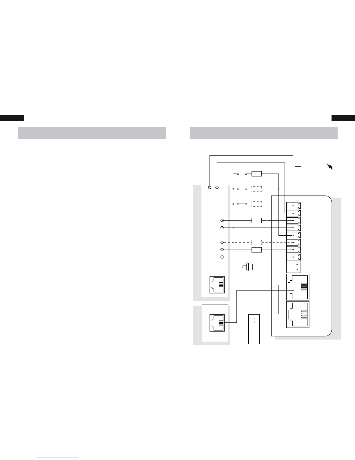
Alarm Panel Phone Line
Multicom 4 Plus
PSTN (MODE3)
IMPORTANT!
Alarm Panel must be
able to supply >300mA
to MC4P. If not, use a
MCPS12 power supply
(available separately).
Optional
Wiring Diagram

4 5Features Features
Features
Product Features
• 4 paths of communications - Dual Carrier
• GPRS x 2
• Contact ID via GSM x 2
• Contact ID via PSTN
• PFP (Poll fail protocol via GSM) x 2
• 3 Paths for programming options
• TechTools App
• PSTN (Attach standard hand set and
program via DTMF tones)
• GPRS
• PSTN Line failure detection based on
time and line voltage threshold (both
programmable)
• PSTN switch over time programmable
(300mS default)
• Power fault detection
• Programmable alarm path priority.
• 4 Zone inputs (EOLR), each zone can be
disabled or enabled.
• The alarm panel attached can be routed
either via MC4P as priority (GPRS Priority), or,
Direct to PSTN (If PSTN is available, the alarm
can communicate directly via PSTN).
• Dedicated local tamper input
• Fault reports for GSM, PSTN, GPRS, Power
Fault, Zones and Tamper. Each group of
alarm events can be mapped to either/or
Relay output and Contact ID
• Programmable Test report time
• Programmable Contact ID client code,
Primary monitoring station number and
• Programmable Relay outputs (Timed and
latched functions via SMS, GPRS)
• Full RSU (Remote Software Update) via
GPRS.
• ComWatch allows the Multicom to monitor,
detect and report failure to communicate
alarm messages via PSTN/GSM/GPRS even if
voltage is present Ref Option 5, 12 and 37.
Technical Features
• Freescale 80Mips 32 bit processor
• Multithreaded Real Time Operating system
for seamless real time path recovery and
system resource management
• Telit GE864 Quad band GPRS modem
• 2 RJ12 connections for phone line in / out
with Mode 3 and Isolation relays built in
• All alarm communication paths have priority
assignment for alarm event communication

6 7Features Features
ComWatch Feature (Patent Pending)
The Multicom does more than just monitor the
PSTN line voltage or GSM network connection to
detect and report a fault. The Multicom monitors
the actual alarm delivery and CMS Receiver kiss
off to ensure the communication was successful
and the PSTN path is validating alarm messages
correctly.
ComWatch has the advantage of detecting
the following faults that cause Contact ID alarm
delivery failures and delivers them via:
• Line voltage being present but not
connecting to the monitoring centre
• Dialling the CMS number(s) but getting
engaged / congestion
• Phone bill on premise not paid: voltage
and dial tone is present but outbound calls
blocked
• Network interconnection faults or
terminating number errors
• 13XX call baring
• CMS Receiver Failures

8 9Quick Start Guide Quick Start Guide
Quick Start Guide
The following gives an overview of the basic
installation steps. For programming options and
methods see the proceeding sections of this manual.
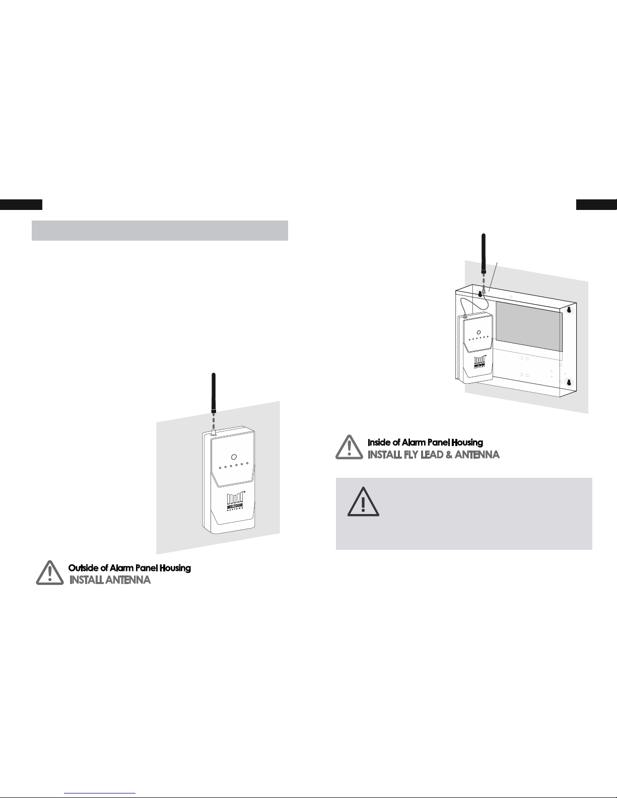
1� Mount the Panel
Fix the included Velcro strip to the back of
the Multicom 4 Plus to mount or place the
box in the desired location. Choose one of
the following mounting options:
OPTION 1
Mounting or
placement outside
the alarm panel
housing requires
the antenna to be
installed directly to
the 4 Plus
OPTION 2
Mounting or
placement inside the
existing alarm panel
housing requires the
be attached and the
included antenna to
be mounted to the
top of the panel
Drill Bit Size - 7mm
Note: If the 4 Plus is being installed in a
poor signal area, please consider using
a high-gain antenna available from
Suretek�

10 11Quick Start Guide Quick Start Guide
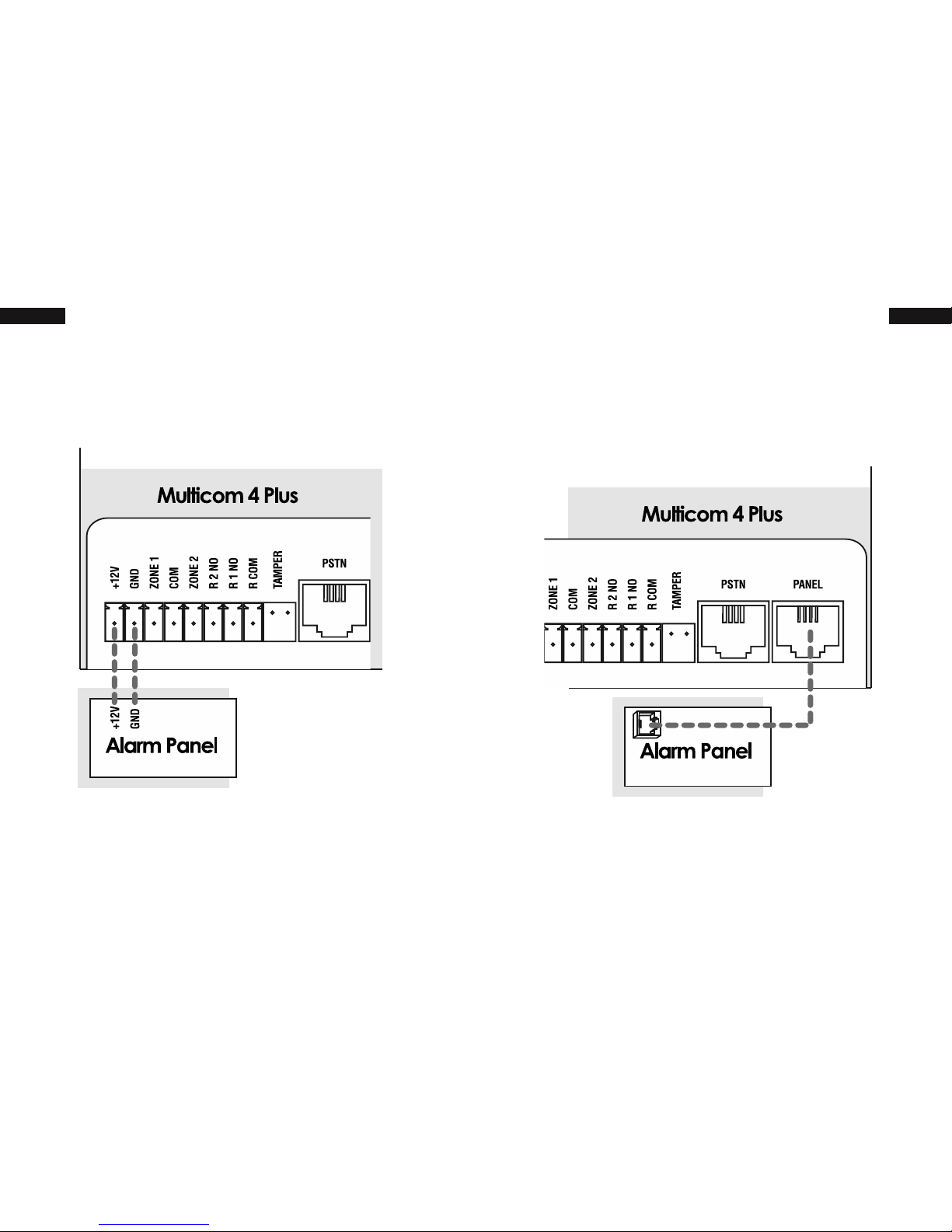
3� Connect to Panel
Connect the “PANEL” connection on the 4
Plus to the “PSTN” connection on the alarm
panel using a 4-wire RJ12 cable.
2� Connect to Power
Connect the 12V+ and GND pins to the 12V
auxiliary output on the alarm panel.
If there is no 12V auxiliary power on the
alarm panel greater than 300mA, connect
to a MCPS12 power supply (available
(>300mA).

12 13Quick Start Guide Quick Start Guide
If not using Zone 2 it is required to seal off
the zone with a 3K3 EOLR�
Note: Steps 4 & 5 are required to meet
Class 4 of the Australian Standard�
5� Interconnect Multicom Relay Output
Input/COM: To notify the alarm panel of MC4P
communication failure, ensure that one of the
MC4P relays is programmed to “COMM’s fail
event” (Relay 1 is programmed to this by default).
Connect the Multicom’s relay output to
one of the Alarm Panel’s Zone Inputs. It is
recommended that the zone on the alarm panel
be a 24 hour audible input. See Option 38.
4� Interconnect Alarm Panel Relay Output
Relay/COM:
of communication failure to the control room,
program one of the alarm panel’s relay outputs
to trigger immediately on PSTN/COMM fail.
Connect the alarm panel’s relay output to one
of the Multicom’s Zone Inputs then ensure that
the zone is enabled. See Option 30.
3K3

14 15Quick Start Guide Quick Start Guide
The second Multicom relay (R2 NO) can be
control other devices such as gates (open &
close) etc. This may be used to arm/disarm
from Multicom smartphone apps. See Option
38.
7� Panel Arm/Disarm or Output Control
(Recommended Option)
6� Connect to the PSTN (Optional)
If PSTN will be used as a communication
path, connect the PSTN socket to a
standard PSTN phone outlet. Mode 3 is
supported.
Note: If you are NOT using PSTN, PSTN fault
detection must be disabled� The operator
will do this during activation or you may
set it using Programming Option 39�

16 17Quick Start Guide Quick Start Guide
8� Test Signal Strength & Device
Power up the 4 Plus. The logo LED’s will act
as a GSM/GPRS signal strength indicator
for the network (Active SIM only in Dual SIM
devices). The GSM, GPRS, COMMS and
POWER LED’s should turn solid green once
connected.
For Dual SIM devices, you
must call the Activations
Centre to check the signal
strength on the Inactive SIM.
The signal levels are reported
to the Activations Centre
once upon power up.
Power cycle to conduct a new network survey�
The survey may take up to 60 seconds�
If signal strength is less than 2 bars
(>95dB), you must relocate the device
or install a high-gain antenna� If
one of the SIMs can not meet signal
requirements, the SIM may be disabled
9� Activate the Device
To enable your Multicom 4 Plus on the
network call the Activations Centre. For
commissioning via phone please have the
required information ready.
• Australia - 1300 603 704
• International - +61 2 8787 9872
Panel ID (0650XXXXX)

18 19Hardware Diagram Hardware Diagram
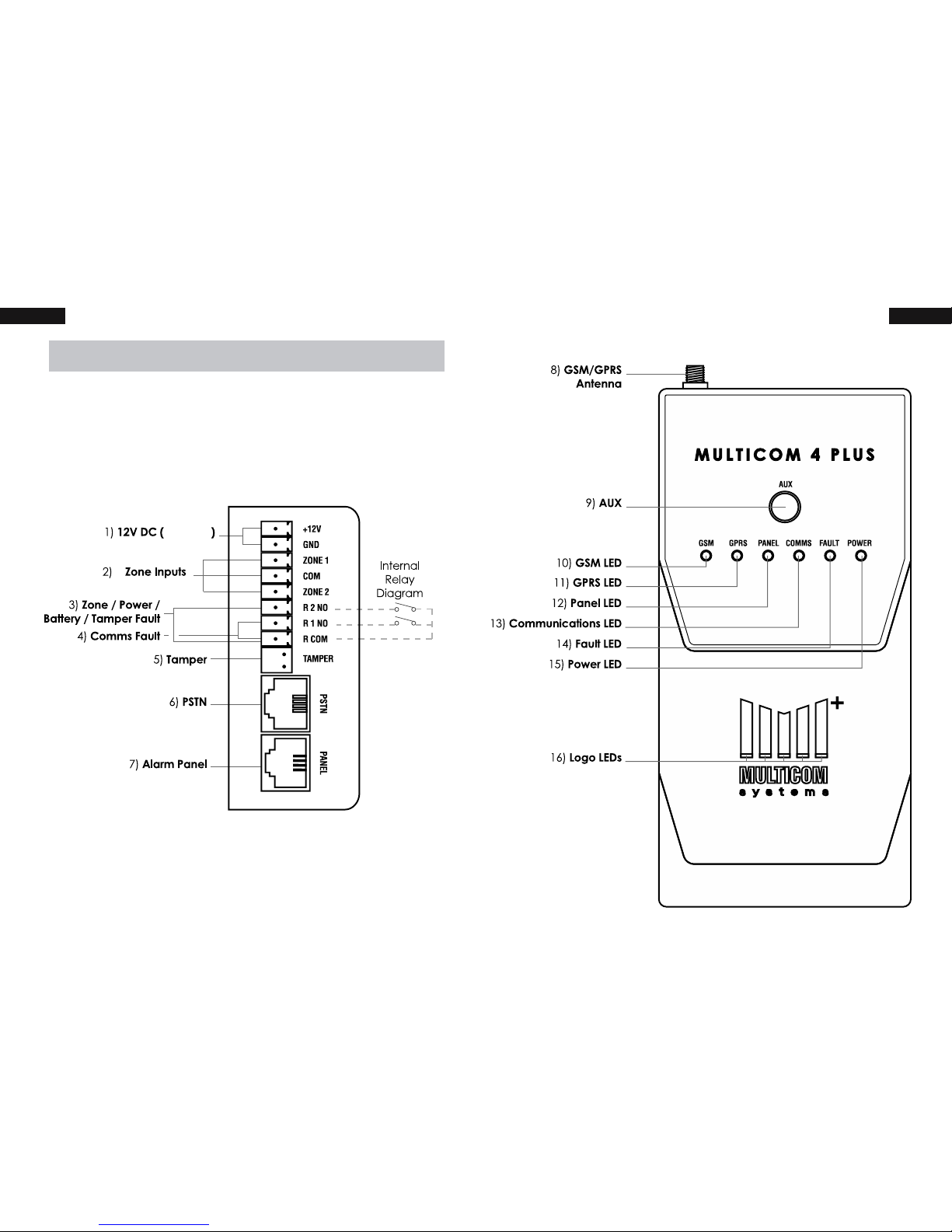
Hardware Diagram
Refer to the next section, “Hardware Diagram
Descriptions“, for descriptions of each component
shown in this diagram.
> 300mA
4
(See Wiring Diagram)

21Hardware Diagram Descriptions20 Hardware Diagram Descriptions
4) Comms Fault (R1 NO / R COM) Relay 1
is programmed as a communications
fault relay. If there is no communication
path available for longer than the pre
programmed time this will remain active until
communications are restored. Note: This
relay can be programmed to be remotely
activated for remote arm/disarm or other
access control functions. Each relay can
Refer to programming option 38.
5) Tamper (TAMPER) Optional. Connect to
the alarm panel tamper zone or similar. This
circuit requires a normally closed tamper (no
EOLR required). If not used, simply leave the
shunt on the connector.
6) PSTN Optional. Connects to standard PSTN
(RJ12 Mode 3, 4-wire).
7) Alarm Panel (PANEL) Connects to the
“PSTN” connection on the alarm panel
using a RJ12 (Mode 3, 4-Wire) cable. This
port can support any alarm system that
communicates using the Contact ID format.
Hardware Diagram Descriptions
Refer to the section, “Hardware Diagram“.
1) 12V DC >300mA (+12V and GND) connect
to a 12V supply capable of supplying at
least 300mA.
2) Zone Inputs (Z1 / Z2 / Z3 / Z4) Each zone
requires a Series End of Line Resistor to be
‘sealed’. Zones 1 and 2 require 3K3. Zones 3
and 4 require 6K8. Refer to Wiring Diagram
on page 3. All zones operate as 24hour
alarm inputs. Zones 1 and 2 are enabled
by default. Zones 3 and 4 are disabled by
default. Refer to Option 30 to change.
3) Zone / Power / Battery / Tamper Fault (R2
NO / R COM) Relay 2 is programmed as an
alarm output. This will activate when an
alarm condition is active on the 4 Plus (Zone,
Power Fault, Tamper active). This relay can
be programmed to be remotely activated
for remote arm/disarm or other access
control functions. Each relay can also have
programming option 38.

22 23Hardware Diagram Descriptions Hardware Diagram Descriptions
11) GPRS LED
ORANGE – GPRS Waiting for Network
Registration
FLASHING ORANGE – GPRS Network
connected, awaiting data connection
GREEN – GPRS Connected
FLASHING GREEN – GPRS
communicating
12) Panel LED (PANEL LED)
FLASHING ORANGE – Initiating
SOLID GREEN – PSTN Line OK
FLASHING GREEN – PSTN or Panel
communicating
SOLID ORANGE – PSTN line not detected
8) GSM / GPRS Antenna The GSM / GPRS
Antenna must be installed. For reliable
operation there must be at least 2 bars of
signal at the time of commissioning. The
system may work on one bar however this is
not an acceptable level.
9) AUX Reserved for future use.
10) GSM LED
FLASHING ORANGE – GSM Booting
SOLID ORANGE – Waiting for GSM
Network registration
SOLID GREEN – GSM Connected to GSM
Network
FLASHING GREEN – GSM
Communicating

24 25Hardware Diagram Descriptions Hardware Diagram Descriptions
RED – Unusable power or power fault
16) Logo LEDs (LED 1-5) The Logo LED’s act as an
indicator of GSM signal level
OFF – No GSM connection/ Booting
1 LED ON – Unactable connection level,
move/adjust the antenna
2 LED ON – Minimum level for
communication
5 LED ON – Full signal
13) Communications LED (COMMS LED)
FLASHING GREEN VERY SLOW – Awaiting
network connection
FLASHING GREEN – Communicating
SOLID GREEN – Communications ok
OFF – Awaiting communications path
14) Fault LED (FAULT LED)
SOLID RED – Fault detected (Power,
Zones, GPRS, GSM, PSTN, or Tamper)
SOLID GREEN – All enabled features are
currently ‘OK’
15) Power LED (POWER LED)
SOLID GREEN – Power supply detected
FLASHING RED/GREEN – Power supply is
outside of normal voltage range

27Panel Programming Methods26 Panel Programming Methods
Log On to the Device
1. Click ‘Panels’ on the main screen
2. Enter the ‘Panel ID’ or scan the device
barcode (Printed on top of Device &
Packaging) and press ‘Go’.
Panel Programming Methods
The following section gives an overview of the
programming methods.
Multicom TechTools Application
and commissions Multicom alarm communicators�
TechTools uses a “TechCode” to identify who has
access to which devices�
Download & Register
1. Download the app from iTunes or Google
Play Store
Visit http://bit.ly/multicom
2. As an installer you should
complete the registration,
take note of your TechCode
and give it to your employer(s) who will in
turn give you permission to work on their
panels. (Employers may need to call 1300
TechCode to their Multicom account)

28 29Panel Programming Methods Panel Programming Methods
Commissioning the Device (Pending App Update)
1. Once logged on to the device click the
‘Commission’ tab.
2. Enter the ‘Bureau’, ‘Control Room’ and
other required reporting details for the
device and press the ‘Activate’ button.
3. Upon successful commisioning you will
receive the alert ‘Panel has been activated
successfully’.
Programming the Device
1. Once logged on to the device click the
‘Program’ tab.
2. Enter the ‘Program Code’ (Default: 1345)
and click OK.
3. You can now edit any available Settings and
click ‘Save’ to upload your changes.

30 31Panel Programming Methods Panel Programming Methods
2� To enter Program Mode press the * key. You
will hear a busy tone. Enter the default
Program Access Code (1345) followed by
#. When a successful code is entered you
will hear a dial tone. You are now in the
program mode. eg. *1345#. See Option
40 to change the Program Access Code.
3� To send a command, follow the
Programming Options table, using the DTMF
row as a guide. Commands with PSTN/DTMF
are sent using the template:
*ADDRESSSETTING# eg. *01ABCD#
4. The Multicom will reply with a dial tone if
your option was updated successfully� The
Multicom will reply with a congested/busy
tone if an error was encountered.
5. To exit program mode press ##. Your 4 Plus
will also automatically exit program mode
DTMF using Phone Handset/Butt
1� Connect the Phone butt to the “Panel”
socket. You will hear a dial tone.
Once connected to the GPRS network,
the 4 Plus can also be programmed
remotely by either your monitoring centre
or from the Suretek National Operations
Centre�

33Programming Options32 Programming Options
Secondary CMS Number / Default: Blank
DTMF * 3 7 1 3 4 5 X X X X #
Program this to the same backup phone number
in the attached panel. This is only used to allow
ComWatch to detect if the panel is attempting to
dial the backup number, the Multicom will not dial
this number.
ComWatch Mode Count / Default: 3
DTMF * 0 5 3#
How many attempts the attached panel has to
correctly deliver a Contact ID message to the
monitoring station before the Multicom takes
priority. Program to 0 to disable. E.g the panel
dials 3 times and no handshake or kiss off tones are
heard, the Multicom will take control of the alarm
delivery path.
ComWatch Mode Bypass Time / Default: 24
DTMF * 1 2 2 4 #
This is the time in hours that the Multicom will hold
priority after ComWatch detects that alarms could
not be delivered via PSTN/GSM.
Programming Options
Account Code / Default: Auto detect
DTMF * 0 19998#
Contact ID account code used by the 4 Plus
Note: Panels that report multiple account codes
may be changed from the code that was initially
taken from the alarm panel. This option can be
changed during the commissioning procedure
with the Suretek Activations Centre.
Primary CMS Number / Default: Blank
DTMF * 0 2 1 3 4 5 X X X X #
Central Monitoring Station Phone number for when
the Multicom communicates via GSM or PSTN (Max
19 digits) eg. 13451111 or 1300111222
/ Default: Blank
DTMF * 1 9 X X X X X #
Optional number for getting an external line out
via PSTN (not GSM) (Max digits is 5)

34 35Programming Options Programming Options
Contact ID Base Message / Default: 18095099900
DTMF * 2 0 XXXXXXXXXX#
This is the default base Contact ID message, refer
to the format template table for individual alarms.
Line Fault Switch Delay / Default: 300
DTMF * 2 5 3 0 0 #
Switching delay for the Mode3 Relays on failure
restore (in milliseconds), Default 300mS. This must
be very quick, as the MC4P will connect directly
to the attached panel to take control of the
communications.
Poll Fail Detection Delay / Default: 150
DTMF * 2 6 1 5 0 #
This monitors all paths for polling within the
programmed time; this is mapped to the relays.
Default 150 seconds. See option 38 for relay map.
Multicom/PSTN Priority / Default: 1
DTMF * 1 1 1#
0 = Multicom is the priority line for the attached
panel, 1 = PSTN is the primary line for the attached
alarm panel
External Panel Programming Timer / Default: Blank
DTMF * 1 3 X X #
Program this in minutes. This feature allows
bypassing of the Multicom for a programmed
period, so that you can program an attached
panel. Connects PSTN to PANEL.
PSTN Fault Threshold (Volts) / Default: 3
DTMF * 1 7 0 3 #
Voltage to detect line failure at (3V default)
Contact ID Retry Delay / Default: 15
DTMF * 1 8 1 5 #
Time delay between Contact ID retries (in
seconds), time is based on the start of dialling,
default 15 seconds.

36 37Programming Options Programming Options
Contact ID Retry Attempts / Default: 5
DTMF * 3 2 5#
How many times to attempt sending a contact
ID message before considering that path to have
failed
PSTN Fault Detection Delay / Default: 60
DTMF * 3 4 6 0 #
How long to wait before detecting PSTN
Communication Fault (60 Seconds default). This
also trips the FAULT Relay (See 38 for relay map).
Relay mapping / Default: 122
DTMF * 3 8 A B C #
ABC, where A = COMM’s fail event, B = Aux alarm
event (Batt + AC), C = External alarm (Zone1-2 and
tamper). Each event can be mapped to:
0 = Not Mapped, 1 = Relay 1, 2 = Relay 2.
Power Fault Detection Delay / Default: 1
DTMF * 2 9 1#
Delay before reporting power fault (in minutes)
Default 1 minute. This is mapped to the fault
relays, see 38. See options 39 for enabling CID
Zone enable / Disable / Default: 1100
ZONE
1 2 3 4
DTMF * 3 0 X X X X #
To enable zones set to one, to disable set to zero.
Default is zones 1 and 2 enabled, zones 3 and
4 disabled. Zones are 24 hour zones. These are
mapped to fault relays by option 38.
Test report time / Default: 24
DTMF * 3 1 2 4 #
The time between test reports for the Multicom (in
hours), default 24 hours. Independent of the alarm
panel & Multicom system polling. Test reports are
sent via the primary path.

38 39Programming Options Panel Programming Methods
Contact ID Event enable/disable / Default: 1
DTMF * 3 9 A B C D #
To disable Event set to 0, to enable set to 1. Default
is all zones enabled. Zones are all 24 hour zones.
Where: A = GPRS Fault, B = Poll Fail,
C = Power Fault, D = PSTN Fault
Program Access Code / Default: 1345
DTMF * 4 0 1 3 4 5 #
This code restricts access to the DTMF
programming mode. Default is 1345.
Table of contents
Other Multi-COM Cell Phone manuals