KEPCO KFD 24-4.2-28W User manual

MODEL
OPERATOR’S MANUAL
IMPORTANT NOTES:
1) This manual is valid for the following Model and associated serial numbers:
MODEL SERIAL NO. REV. NO.
2) A Change Page may be included at the end of the manual. All applicable changes and
revision number changes are documented with reference to the equipment serial num-
bers. Before using this Instruction Manual, check your equipment serial number to identify
your model. If in doubt, contact your nearest Kepco Representative, or the Kepco Docu-
mentation Office in New York, (718) 461-7000, requesting the correct revision for your par-
ticular model and serial number.
3) The contents of this manual are protected by copyright. Reproduction of any part can be
made only with the specific written permission of Kepco, Inc.
Data subject to change without notice.
KEPCO®
THE POWER SUPPLIER™
ORDER NO. REV. NO.
KEPCO INC.
An ISO 9001 Company.
KEPCO, INC. !131-38 SANFORD AVENUE !FLUSHING, NY. 11352 U.S.A. !TEL (718) 461-7000 !FAX (718) 767-1102
email: hq@kepcopower.com !World Wide Web: http://www.kepcopower.com
©1995, KEPCO, INC
P/N 243-0818
KFD 150W
POWER SUPPLY
24 VOLTS OUTPUT
18 TO 36 VDC INPUT
KFD 24-4.2-28W
POWER SUPPLY


KFD24-4.2-28W/ 060801 i
TABLE OF CONTENTS
SECTION PAGE
1.0 Introduction:............................................................................................................................................. 1
2.0 Description: ............................................................................................................................................. 1
3.0 Absolute Maximum Ratings:.................................................................................................................... 1
4.0 Input Specifications ................................................................................................................................ 1
5.0 Output Specifications ............................................................................................................................. 2
6.0 General Specifications ............................................................................................................................ 3
7.0 Feature Specifications ............................................................................................................................ 4
8.0 Output Overvoltage Clamp...................................................................................................................... 4
9.0 Current Limit............................................................................................................................................ 4
10.0 Remote ON/OFF ..................................................................................................................................... 4
11.0 Output Voltage Reversal ......................................................................................................................... 5
12.0 Isolation ................................................................................................................................................... 5
13.0 Parallel Operation.................................................................................................................................... 5
14.0 Forced Load Sharing............................................................................................................................... 5
15.0 Remote Sense......................................................................................................................................... 6
16.0 Safety Considerations ............................................................................................................................. 6
17.0 Output Voltage Trim ................................................................................................................................ 6
18.0 Thermal Considerations .......................................................................................................................... 7
18.1 Case Temperature............................................................................................................................. 7
18.2 Forced Convection............................................................................................................................. 7
18.3 Heat Sink Models............................................................................................................................... 7
18.4 Natural Convection ............................................................................................................................ 7
18.5 Use of Graphs.................................................................................................................................... 8
18.6 Thermal Models................................................................................................................................. 8
18.7 Detailed Thermal Model..................................................................................................................... 9
18.8 Radiation Heat Transfer..................................................................................................................... 9
18.9 Horizontal Orientation ........................................................................................................................ 9
19.0 Fusing Considerations............................................................................................................................. 9
20.0 General Features .................................................................................................................................. 10
21.0 Applications ........................................................................................................................................... 10

ii KFD 24-4.2-28W/060801
LIST OF FIGURES
FIGURE TITLE PAGE
1 Test Setup For Output Voltage And Efficiency Measurements For The DC to DC Converter ................ 11
2 Test Setup for the Input Reflected Ripple for the Single Output KFD DC To DC Converter................... 12
3 Mechanical Outline Drawing of the Single Output KFD DC to DC Converter .......................................... 13
4 Remote On/Off Wiring Configuration for the Single Output KFD DC to DC Converter ............................ 14
5 wiring configuration for redundant parallel operation of the KFD DC to DC Converter ............................ 15
6 Circuit Configuration for Single KFD DC to DC Converter Remote Sense Operation.............................. 16
7 (Top) KFD DC to DC Converter Circuit Configuration for RTrim Down,
to Decrease Voltage Setpoint............................................................................................................... 17
8 (Bottom) KFD DC to DC Converter Circuit Configuration for RTrim Up,
to Increase Voltage Setpoint ................................................................................................................. 17
9 Heat Sinks for Vertical Orientation - Kepco Model KFD-02 and the Kepco Model KFD-04 .................... 18
10 Heat sinks for Horizontal Orientation - Kepco Model KFD-01 and the Kepco Model KFD-03.................. 19
11 Forced Convection Derating, Power Dissipation Versus Local Ambient Temperature ........................... 20
12 Heat Sink Derating Curves, Natural Convection, Fins Oriented Along the Width .................................... 21
13 Heat Sink Derating Curves, Natural Convection, Fins Oriented Along the Length .................................. 22
14 Heat Sink Resistance Curves for Fins Oriented Along Vertical and Horizontal directions ....................... 23
15 Power Dissipation Versus Output Load for Three Different Input Voltages ............................................. 24
LIST OF TABLES
TABLE TITLE PAGE
1 Input Specifications .................................................................................................................................... 1
2 Output Response for the KFD Unit ............................................................................................................. 2
3 Dynamic Response for the KFD UniT ....................................................................................................... 2
4 Output Specifications ................................................................................................................................. 3
5 General Specifications ............................................................................................................................... 3
6 Remote On/Off ........................................................................................................................................... 4
7 Feature Specifications ................................................................................................................................ 4

KFD 244.228W/060801 1
1.0 INTRODUCTION:
SCOPE OF MANUAL: This instruction brief contains information for the installation and operation of the
Kepco KFD 150 Watt DC to DC Converter. For further operating and service information for the KFD 150
Watt DC to DC Converter contact your Kepco Representative directly, or write to Kepco, Inc., 131-38 San-
ford Avenue, Flushing, New York 11352 U.S.A.
2.0 DESCRIPTION:
The Kepco KFD 150 Watt DC to DC Converter has a nominal 18-36 Vdc input and a 24 Volt DC output
nominal voltage. The DC to DC Converter is a low-dissipative stabilizer, using pulse-width modulation to
control the output. The unit features input/output isolation and remote ON/OFF. Remote ON/OFF is accom-
plished by an isolated TTL level signal that may use either mechanical or solid state closure. The output
voltage may be adjusted with a trimmer terminal located in the upper right hand corner of the unit (see Fig-
ure 3, top view). The unit is guaranteed for one year when operated within the specifications given herein.
3.0 ABSOLUTE MAXIMUM RATINGS:
The DC to DC Converter described in this manual is rated for continuous operation when used in an ambi-
ent temperature range of 0° to 71°C. Within this range the unit will operate according to the specifications
listed below, provided they are not subject to stress. The unit will function with degraded reliability and life
if operated at the extreme ends of the temperature range, at -40° to 0°C,or 71°C to 90°C. Specifications
Do Not Apply Throughout The Entire Operating Range (-40° To 90°C)
STRESSES IN EXCESS OF THE MAXIMUM RATINGS can cause permanent damage to the unit. THESE
are absolute stress ratings only. Functional operation of the unit is not implied at these or any other condi-
tions in excess of those in the following tables.
The following specifications apply to the power supply model listed below:
4.0 INPUT SPECIFICATIONS (SEE TABLE 1):
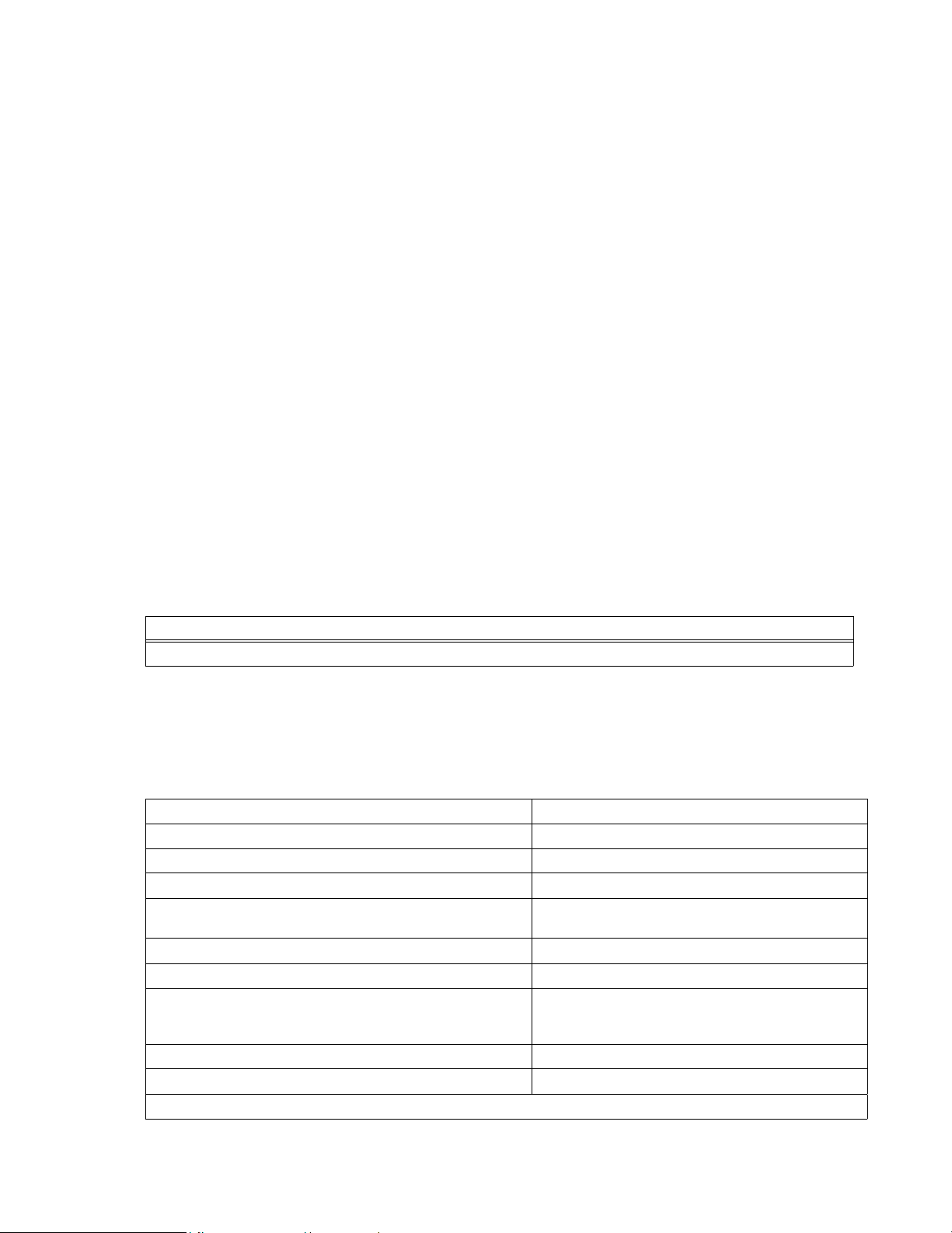
MODEL INPUT OUTPUT
KFD 24-4.2-28W 18-36 VOLTS DC 24 VDC 4.2A
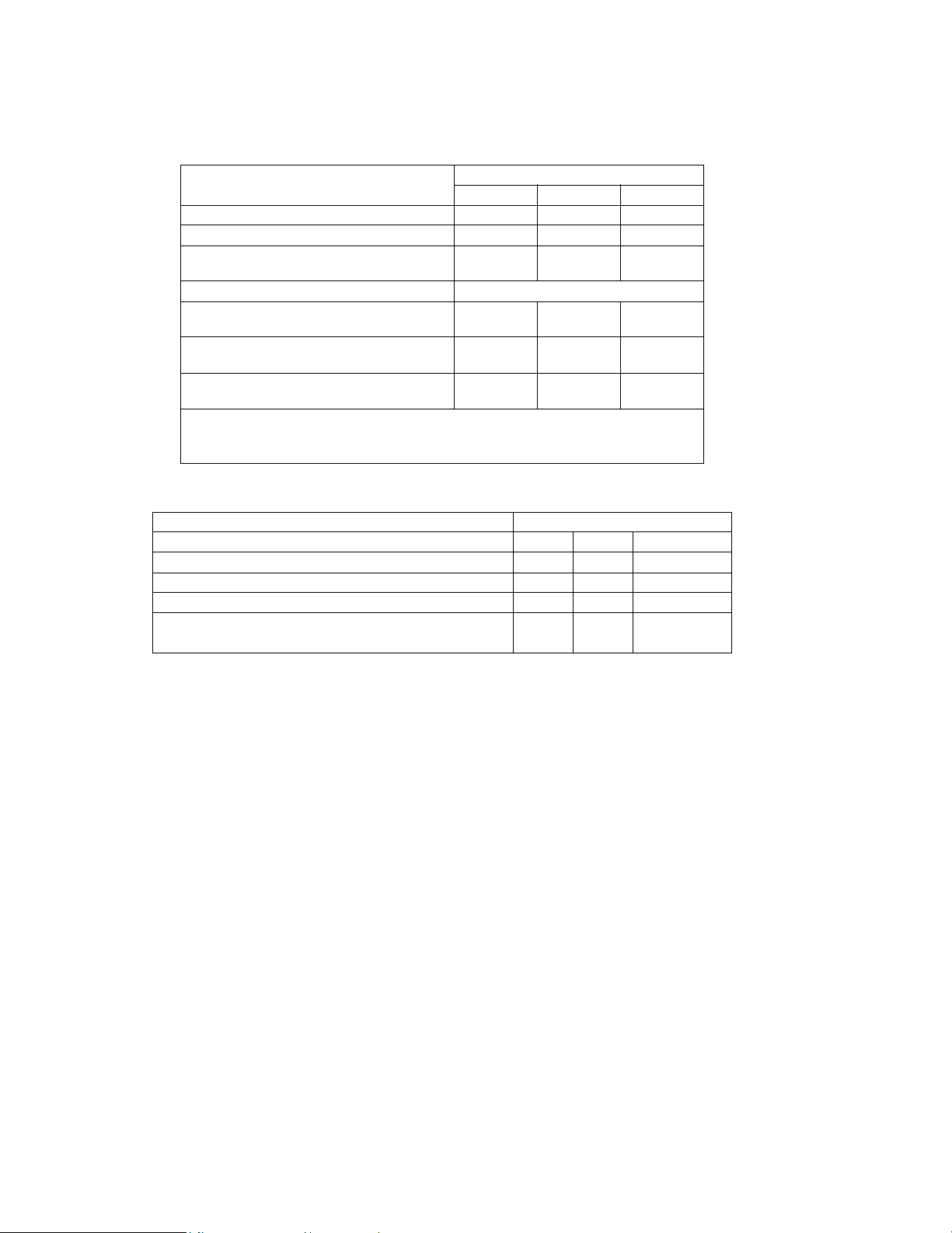
TABLE 1. INPUT SPECIFICATIONS
Parameter Description
Nominal Input Voltage 28 Vdc
Input Voltage Range 18-36 Vdc
Input Current Maximum* 8A (VI=0 to 36 Volts)
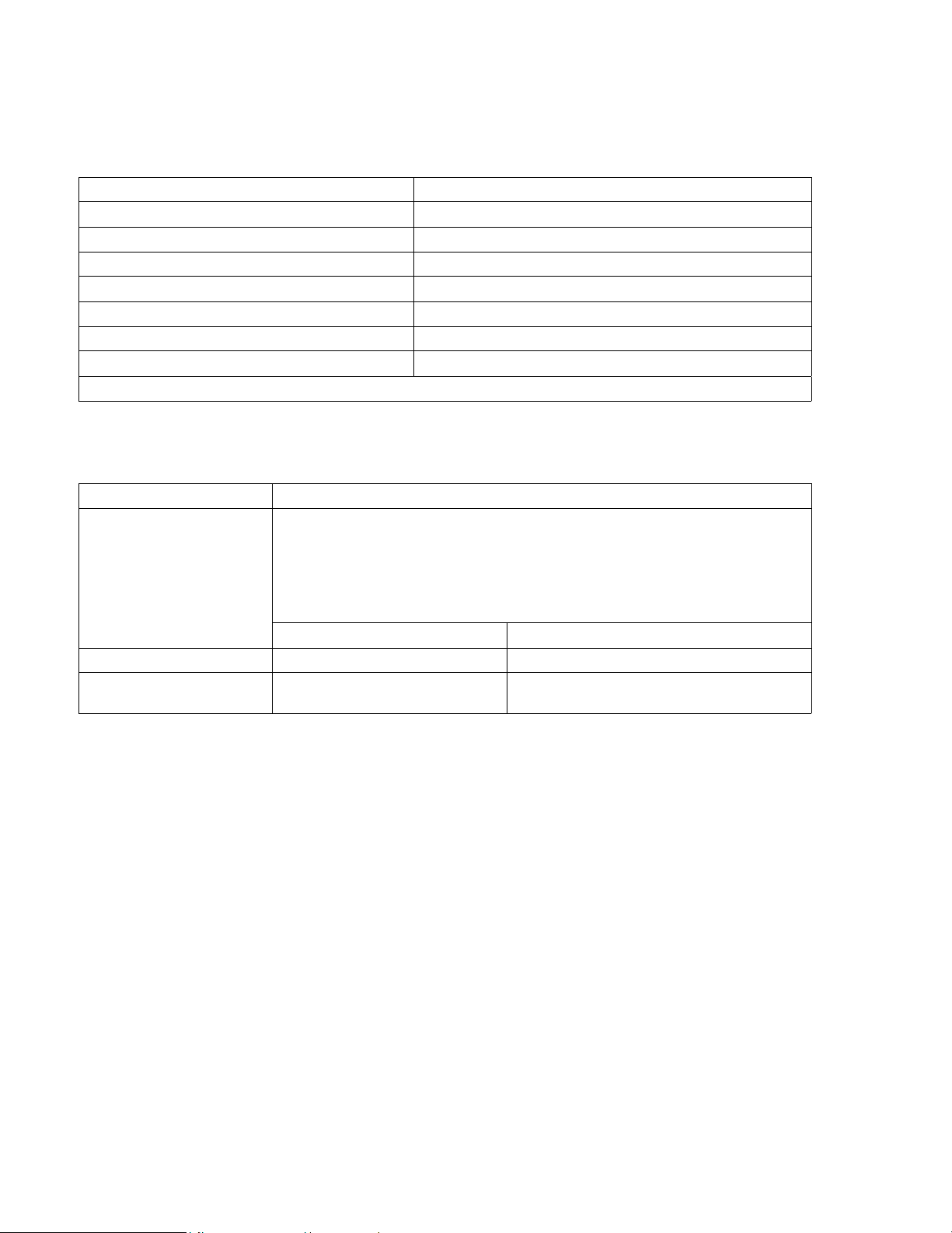
Efficiency: VI=48 Volts, Io= Io, max.;TA=20°C
See Figure 1
90% typical
86 minimum
Switching Frequency 100KHz
Circuit Type Forward Converter
Input Reflected Ripple Current
(peak to peak,5Hz to 20 MHz, 12µH source impedance,
TA=25°C, see Figure 2)
20 mA peak to Peak
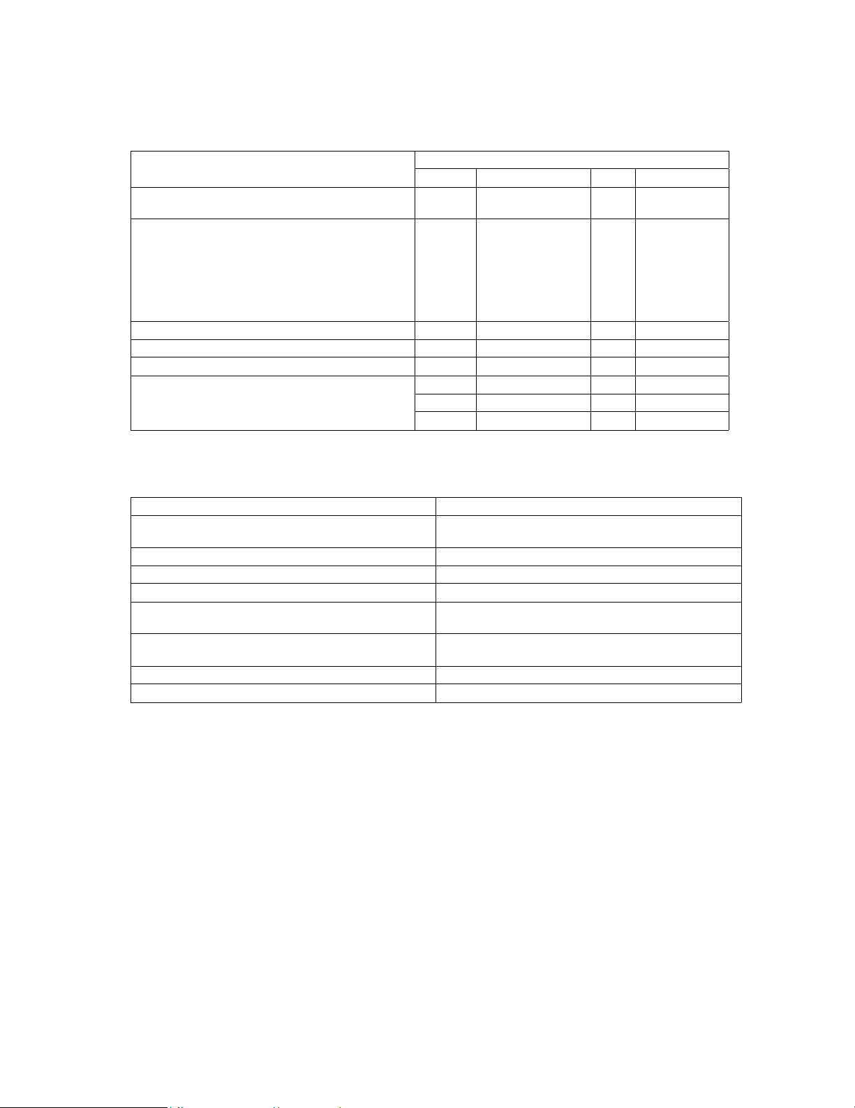
Input Ripple Rejection (120Hz) 60 dB typical
Inrush Current (I2t) 2.0 A2s maximum
*THE KFD MODULE IS NOT INTERNALLY FUSED, AN INPUT LINE FUSE MUST ALWAYS BE USED

2KFD 244.228W/060801
5.0 OUTPUT SPECIFICATIONS (SEE TABLES 2, 3, AND 4)
TABLE 2. OUTPUT SPECIFICATIONS FOR THE KFD UNIT
Parameter Description
Output Voltage Nominal 24V
Output Current Nominal 4.2A
Output Power Maximum 100W
Ripple1200mV RMS max.
Noise, 5Hz to 20Mhz 500 mV p-p max.
Output Current Minimum 1.0A
Output Current Maximum 4.2A
1At less than minimum load the DC to DC converter may exceed its output ripple specification
TABLE 3. DYNAMIC RESPONSE FOR THE KFD UNIT
Characteristic Specification
Dynamic Response to Load
Change
VI=28 Volts, TA=25°C
From Io = 50% to 75% Io,max
and from Io=50% to 25% Io,max.
Typical Unit
Peak Deviation 700 mV
Settling Time (Vo< 10% of
Peak Deviation) 300 µS
∆Io
∆T
----------1A
10
µ
S
--------------=

KFD 244.228W/060801 3
6.0 GENERAL SPECIFICATIONS (SEE TABLE 5)
TABLE 4. OUTPUT SPECIFICATIONS
Parameter Specification
MIN MAX TYP UNIT
Output Voltage (Over All Operating Input Voltage,
Resistive Load, And Temperature Conditions) 22.8 25.2 Vdc
Output Voltage Setpoint (VI=48 volts, Io= Iomax,
TA=25°C.
Unit Operating In Parallel Or Parallel Pin Shorted
To Sense (-) Pin (See Figure 3)
Parallel Pin Open
23.5
23.5
24.5
24.5
24.00
24.00
Vdc
Vdc
Output Short Circuit Current (250mV) 7.14 5.67 A
Output Current Limit Inception 4.33 5.46 A
Output Current 4.2 A
Output Regulation : Line Vi= 18 to 36 Volts
Load Io= 1.0A to Iomax
Temperature -TA=0°C° to 90°C
0.2% 0.05% %
0.4% 0.2% %
300 mV
TABLE 5. GENERAL SPECIFICATIONS
Parameter Specification
Case Temperature (min-max) Operating: 0° to 90°C
Storage: -40°C to 125°C
Isolation Resistance 10M Ohms Minimum
Isolation Capacitance 1700 pF Typical
I/O Isolation Voltage 500 Vdc Maximum
Calculated MTBF
(at 80% of Io, max ,T = 40°C) 920000 Hours
Dimensions 0.66(16.8) X 4.8(121.9) X 2.5(63.5)
See Mechanical Outline Drawing, Figure 3
Weight 7.0 OZS (198.45 Grams) Maximum
Cover Material Non- Conductive Material

4KFD 244.228W/060801
7.0 FEATURE SPECIFICATIONS (SEE TABLES 6 AND 7)
8.0 OUTPUT OVERVOLTAGE CLAMP
The KFD output voltage is controlled by the primary regulation loop. The control circuitry for the overvolt-
age clamp is independent of the KFD DC to DC Converter primary regulation loop. A secondary output
voltage control is provided by the overvoltage clamp circuitry, thereby reducing the possibility of output
overvoltage. This is realized by having the set point of the overvoltage clamp designed to be higher than
the set point of the primary loop.
9.0 CURRENT LIMIT
The KFD DC to DC Converter is protected against output overload by internal current limiting. This mode
of operation can be maintained for an unlimited time duration provided that the case temperature is main-
tained at or below 90°C. At the very point of current limit inception the DC to DC converter shifts from a
voltage control to a current control mode.
10.0 REMOTE ON/OFF
The DC to DC Converter can be remotely controlled via a switch (that the user must supply) across the
ON/OFF terminal and the -VI terminal (VON/OFF). At logic low VON/OFF=0 to 1.2 Volts, the unit is ON; and the
maximum ION/OFF (when the module is ON) is 1 mA. The switch should be able to sink 1 mA when it is at a
logic low voltage. At logic high the maximum VON/OFF of the KFD unit is 18 Volts. The maximum allowable
leakage current of the switch (at logic high) is then 50µa.
TABLE 6. REMOTE ON/OFF
State Specification
Typ Max Unit
ON/.OFF CURRENT Logic Low 1.0 ma
ON/OFF VOLTAGE Logic Low 1.2 V
Logic High
ION/OFF=0 18 V
Open Collector Switch Specifications
Leakage Current During Logic High
(VON/OFF=18V) 50 µΑ
Output Low Voltage During Logic Low
ION/OFF =1mA 1.2 V
Turn On Time (Io =80%Iomax.; Vo within ±1%
of Vo,set)
5 10 ms
NOTES: 1. Remote On/Off (0 Volts <V1< 36 Volts, Open Collector Or Equivalent, Signal
Referenced to -V1 Terminal)
2. Logic Low-module ON; Logic High-module OFF
TABLE 7. FEATURE SPECIFICATIONS
Parameter Specification
Typ Max Unit
Output Overvoltage Clamp, 26.4 Volts Minimum 29 32 V
Output Voltage Sense Range 2.4 V
Output Voltage Set Point Adjustment Range 26.4
Parallel Operation Load Sharing 20%
Io,max,

KFD 244.228W/060801 5
A jumper across the ON/OFF terminal and the -VI terminal can be used to override the Remote ON/OFF
(see Figure 4). Either a user-supplied switch or the override jumper should be wired into the circuit via indi-
vidual PWB current paths not common to the -VIcurrent path. Connect the switch or jumper wire at the
KFD terminals, across the common connection point and the Remote ON/OFF point. This connection will
prevent noise from falsely triggering the Remote ON/OFF.
11.0 OUTPUT VOLTAGE REVERSAL
12.0 ISOLATION
The KFD output is fully isolated from the input. The KFD DC to DC Converter is encapsulated in noncon-
ductive cases that mount on PC boards. The module is rated to full load at 71°C in a natural convection
environment (without a heat sink or external filter).
13.0 PARALLEL OPERATION
The Power Module can be configured for parallel operation with forced load sharing, to provide for redun-
dant operation or to satisfy additional power requirements. For a typical redundant operation, Schottky
diodes or equivalent should be used to protect against a short circuit condition. The forward voltage drops
across the diodes do not affect the set point voltage applied to the load because of the remote sensing
compensation. If multiple units are used to develop combined power, in excess of the rated maximum (to
satisfy additional power requirements), the Schottky diodes are not required.
14.0 FORCED LOAD SHARING
To implement forced load sharing, the following connections must be made at the pins of the KFD unit. In
addition to that the wiring configuration must be arranged in a way that is compatible with good noise
immunity
a) The parallel pins of all the units connected in parallel must be connected together. The paths of
these connections must be as direct as possible.
b) All Remote Sense pins must be connected to the D.C to D.C. Converter bus at the same point. Connect
all Remote Sense (+) terminals to the (+) side of the power bus at the same point, and all Remote Sense
(-) terminals to the (-) side of the power bus at the same point.
CAUTION
Do not apply a reverse polarity voltage across the KFD output terminals. Such an
application will forward bias an internal diode of the Power Module and damage
the KFD unit.
NOTE
CLOSE PROXIMITY AND SHORT CONNECTING WIRES ARE NECESSARY
FOR GOOD NOISE IMMUNITY

6KFD 244.228W/060801
15.0 REMOTE SENSE
Remote Sense pins are provided to minimize the effects of distribution losses that come about from regu-
lating the output voltage at the remote sense terminals. The KFD output voltage specifications refer to
measurements taken at the Remote Sense terminals during parallel operation, or with the parallel pin
shorted to the Sense (-) pin. The voltage between the Remote Sense pins and the KFD output terminals
must not exceed the output voltage Sense range given in the KFD specifications. The combination of out-
put set point adjustment range and output voltage Sense range given in the Feature Specifications Table,
Table 7 cannot exceed 16.5 Volts between the Vo (+) and Vo (-) terminals.
16.0 SAFETY CONSIDERATIONS
For Safety Standard approval, the system that the Power Module is used in, must satisfy the following con-
dition:
The Power Module must be installed in compliance with the spacing and separation requirements of the
End Use Safety Agency Standard i.e., UL-1950, CSA 22.2-950, EN 60 950.
For the Converter output to satisfy the requirements of the Safety Extra Low Voltage Standard (SELV), one
of the following conditions must be valid for the D.C. input:
The Converter input meets all requirements of SELV, or
The Converter must be provided with reinforced insulation to protect against hazardous voltages, including
the A.C. mains; and comply with SELV reliability tests.
17.0 OUTPUT VOLTAGE TRIM
The output trim feature provides for the capability of increasing or decreasing the output voltage setpoint of
the Power Module. This can be accomplished by using an external resistor between the TRIM pin and
either the SENSE (+) or SENSE (-) pin (see Figures 7 and 8).
With an external resistor connected between the TRIM pin and SENSE (–) pin (RTRIM-UP), the output volt-
age setpoint (Vo, TRIM) increases to the higher voltage defined in this equation:
With an external resistor connected between the TRIM pin and the SENSE (+) pin (RTRIM-DOWN), the out-
put voltage setpoint (Vo, TRIM) decrease to the lower voltage defined by this equation:
The Combination of output set point adjustment range and output voltage Sense range, given in the Fea-
ture Specifications Table 7, cannot exceed 26.4 Volts across the Vo (+) and Vo (-) terminals (see Figures
6, 7 and 8).
RTRIM UP–
1.25
VoTRIM
,24–
--------------------------------------------
90900
=
RTRIM DOWN–
VoTRIM,1.25–
24 VoTRIM,
–
--------------------------------------------
90900()=

KFD 244.228W/060801 7
18.0 THERMAL CONSIDERATIONS
To ensure reliable operation of the KFD unit, thermal management is important. Heat dissipated by the unit
is conducted to the case, and subsequently convected to the surrounding air. Convection cooling can be
improved by mounting a heat sink to the top of the unit. Six threaded holes, No. 4-40 [0.18 inches deep
(46mm)] are provided for this purpose. A dry pad or thermal compound should be used to minimize thermal
resistance between the case and the heat sink. The case temperature should not exceed 90 degrees C.
18.1 CASE TEMPERATURE
Proper cooling for the KFD D.C. to D.C. Converter can be verified by measuring the case temperature of
the module. It is measured on the top surface of the unit at a sensing point---3 inches (76mm) from the left
edge of the power module, and 0.7 inches (18mm) from the top edge of the unit. The case temperature
must not exceed 95°C while the unit is operating in the final system configuration. After the module has
reached thermal equilibrium, the measurement can be made with a thermocouple or surface probe. If a
heat sink is mounted to the case, make the measurement at the base of the heat sink as close as possible
to the heat sensing point. The contact resistance between the mounting surface and the heat sink must be
taken into account when making this measurement.
Maintaining the operating case temperature (Tc) within the specified range keeps internal component tem-
peratures within their specifications. That in turn helps keep the expected mean time between failure
(MTBF) from falling below the specified rating. The KFD Power Module is designed with temperature resis-
tant components such as ceramic capacitors that do not degrade during prolong exposure to high temper-
atures, as do aluminum electrolytic capacitors.
18.2 FORCED CONVECTION
The discussion that follows can be applied to all high powered KFD board mounted power modules in the
4.8in (121.9mm) x 2.5in (63.5mm) x 0.5in (12.7mm) package.
Increasing the air flow over the module improves cooling. In that regard Figure 11 shows the power derat-
ing (PD) versus local ambient temperature (TA) at air flows, from natural convection to 800 ft./min. (4.1 m/
s). The curves in this Figure were obtained from measurements made in a free stream of air approaching
a vertically oriented module on a printed wiring board, positioned in a rectangular passage. The Figure
can be used to determine the appropriate air flow for a given set of operating conditions.
For example, at PD=20W and TA=40°C, an air flow of 200 ft./min. (1.0 m/s) is sufficient to keep the module
within its ratings.
18.3 HEAT SINK MODELS
Figures 9 and 10 show a number of standard heat sinks that are available for the KFD Power Module,
labeled with their respective thermal resistances for natural convection. The heat sinks mount to the top
surface of the power module using No. 4-40 hardware, torqued to 5 in.lbs. To minimize contact resistance
and temperature drops, use a thermally conductive dry pad or thermal grease between the case and heat
sink.
18.4 NATURAL CONVECTION
The plots in Figures 12 and 13 represent power derating for a power module in natural convection when
attached to various heat sinks (these include designs with fins oriented along the length and designs with

8KFD 244.228W/060801
the fins oriented along the width). Natural convection is the air flow produced when air in contact with a
hot surface is heated. An open environment is required with no external forces moving the air. The Figures
apply when the power module is the only source of heat present in the system.
18.5 USE OF GRAPHS
First determine the amount of power that is to be dissipated as heat, as well as the ambient operating tem-
perature. Plot the data on the graph, and note the intersection point; the point indicates the appropriate
heat sink to use. For instance, if PD=20 W and Ta=30°C, a 0.5 inch (12.7mm) heat sink with fins oriented
along the width, would keep the module within its operating temperature rating
18.6 THERMAL MODELS
The curves in Figure 14 are plots of thermal resistance against air velocity, for various types of heat sinks;
with fins oriented along the width and with fins oriented along the length. The plots are determined experi-
mentally without a heat sink and with the heat sinks illustrated in Figures 9 and 10 . The highest values on
the curves represent natural convection. In a system with free flowing air and other heat sources, there
may be additional air flow.
The following two examples illustrate how the curves can be used to determine thermal performance under
various air flow and heat sink configurations.
Example 1: To determine the air flow required to maintain Tc,max (case temperature)=95°C for the KFD
100W D.C. to D.C. Converter (the KFD 24-4.2-28W) without a heat sink, consider the following:
The KFD DC to DC Converter (100W) operates at Io=4.2 Amps and TA=50° without a heat sink. The power
dissipated by the unit can be determined from the difference between the input power and output power
and the efficiency of the converter. It can be noted that the unit has a power dissipation of 11.1 watts. The
thermal resistance that is necessary to maintain a 95°C case temperature is determined from the equa-
tions that follow:
The total thermal resistance of the unit is defined as the maximum case temperature rise divided by the
power dissipation of the module:
ϑ= Total thermal resistance
∆Τc max = Maximum case temperature rise
PD= Power dissipated as heat
From Figure 14 the required air flow necessary to maintain a 95°C case temperature then is about 75 ft./
min. (0.375 m/s)
Example 2: How to determine the case temperature for a specific operating environment. Say for exam-
ple, that only an air flow of 150 ft./min is available and it is required to determine the case temperature
θTcmax,TA
–()
PD
----------------------------------------------=
θ95 50–()11.1 )÷ 4.05 °C
W
-------
==

KFD 244.228W/060801 9
using a one half inch fin heat sink oriented along the length. Consider the following:
For an air flow of 150 ft./min. using the same D.C. to D.C. Converter as in the last example and with a 0.5
inch heat sink with fins oriented along the length, refer to the thermal resistance plot. From Figure 14 the
thermal resistance is 1.3°C/W.
After the delta change in case temperature is calculated, the actual case temperature is determined by the
following:
18.7 DETAILED THERMAL MODEL
The thermal resistance previously includes heat transfer by conduction, convection, and radiation, from the
entire module to the surrounding environment. Typically the KFD power module is soldered to a vertically
oriented printed wiring board. Most of the heat transfer is by convection and radiation from the top mount-
ing surface of the module. Significant amounts of heat are also removed by convection from the sides of
the module, by conduction by the printed wiring board, and by convection off of the opposite side of the
printed wiring board
18.8 RADIATION HEAT TRANSFER
Radiation is not dependent upon the air flow over the power module, but on the temperature difference
between the module and the surrounding environment. For a particular KFD power module, θ Rdue to
radiation can be determined experimentally. For the KFD high power modules operating at Tc=95°C and
Ta = 2 5° C , θ R (Radiation Resistance) =15°C/W
18.9 HORIZONTAL ORIENTATION
In some applications the power module is operated in natural convection and oriented horizontally. In that
situation θTOTAL =4.8°C/W for the overall module thermal resistance (including the base plate resistance).
19.0 FUSING CONSIDERATIONS
The encapsulated KFD Power Module can be used in a stand alone operation, or as an integrated part of
a complex power architecture. To achieve maximum safety and system protection always use an input line
fuse. To aid in the proper fuse selection for a given application, information on inrush energy and maximum
current is provided in the KFD specifications. It is also recommended to refer to the fuse manufacturer's
∆TCPDθ)(
=
∆TC11.1 1.3() 14.43 °C==
TCTA∆TC
+()50°C14.43°C+()64.43°C===
CAUTION
THE KFD MODULE IS NOT INTERNALLY FUSED; AN INPUT
LINE FUSE MUST ALWAYS BE USED

10 KFD 244.228W/060801
data for additional data.
20.0 GENERAL FEATURES
Among the general features of the KFD D.C. to D.C. Converter are the ones listed below:
• Low Profile: 0.5 inch
• Internal EMI Filter
• Complete Input And Output Filtering
• Input To Output Isolation
• Short Circuit Protection
• Output Overvoltage Clamp: 26.4 Volts minimum
• High Efficiency: 90% Typical
• Fabricated with Surface Mount Technology
• Compatible for printed circuit board mounting
• Compatible for heat sink
• Meets FCC Requirements for Telecommunications
21.0 APPLICATIONS
Among the possible applications of the KFD D.C. to D.C. Converter are the following:
• Redundant Power Architecture
• Distributed Power Architecture
• Telecommunications
• Private Branch Exchange

KFD 244.228W/060801 11
FIGURE 1 TEST SETUP FOR OUTPUT VOLTAGE AND EFFICIENCY
MEASUREMENTS FOR THE DC TO DC CONVERTER
NOTE: WHEN PLACING THE POWER MODULE INTO A PRINTED CIRCUIT BOARD
SOCKET, USE KELVIN CONNECTIONS AT THE POWER MODULE INPUT
AND OUTPUT TERMINALS TO AVOID MEASUREMENT ERRORS DUE TO
SOCKET CONTACT RESISTANCE.

12 KFD 244.228W/060801
FIGURE 2 TEST SETUP FOR THE INPUT REFLECTED RIPPLE FOR
THE SINGLE OUTPUT KFD DC TO DC CONVERTER.
NOTE: AT THE INPUT THE REFLECTED RIPPLE IS MEASURED WITH A SIMU-
LATED SOURCE IMPEDANCE OF 12µH; THE CAPACITOR, Cs, OFFSETS
POSSIBLE BATTERY IMPEDANCE. CURRENT IS MEASURED AT THE
INPUT OF THE POWER MODULE.

KFD 244.228W/060801 13
FIGURE 3 MECHANICAL OUTLINE DRAWING OF THE SINGLE OUT-
PUT KFD DC TO DC CONVERTER
3040526

14 KFD 244.228W/060801
FIGURE 4 REMOTE ON/OFF WIRING CONFIGURATION FOR THE
SINGLE OUTPUT KFD DC TO DC CONVERTER
3040491

KFD 244.228W/060801 15
FIGURE 5 WIRING CONFIGURATION FOR REDUNDANT PARALLEL
OPERATION OF THE KFD DC TO DC CONVERTER

16 KFD 244.228W/060801
FIGURE 6 CIRCUIT CONFIGURATION FOR SINGLE KFD DC TO DC CONVERTER
REMOTE SENSE OPERATION
Table of contents
Other KEPCO Power Supply manuals

KEPCO
KEPCO HSF 5-60M User manual

KEPCO
KEPCO BOP 2KW-MG Series User manual

KEPCO
KEPCO BOP 1000W User manual

KEPCO
KEPCO JQE 6-22 User manual

KEPCO
KEPCO TBC Series User manual

KEPCO
KEPCO HSF 3.3-25-1UR User manual

KEPCO
KEPCO HSF-A Series User manual

KEPCO
KEPCO HSF 12-53 User manual

KEPCO
KEPCO BOP-1KW User manual

KEPCO
KEPCO HSF 5-10-1U User manual

KEPCO
KEPCO PAT 40-0.5 User manual

KEPCO
KEPCO HSF-1UR 50W Series User manual

KEPCO
KEPCO BOP 5-20DL User manual

KEPCO
KEPCO HSF 12-53A User manual

KEPCO
KEPCO HSF 3.3-20PFC User manual

KEPCO
KEPCO TBC 12-50M User manual

KEPCO
KEPCO FAW 5-3K User manual

KEPCO
KEPCO MAT Series User manual

KEPCO
KEPCO HSF 5-20 User manual

KEPCO
KEPCO HSF 5-60 User manual