Multifan 130 Parts list manual

Galvanized Box Fan 130
ENGLISH
Installation Instructions - Operating Instructions
Document ID: INS00025-A
IMPORTANT - READ CAREFULLY BEFORE USE

Galvanized Box Fan 130
2 | ENGLISH Original instructions INS00025-A
Table of Contents
1 Introduction ...........................................................................................2
2 Safety...................................................................................................... 2
3 Safety instructions................................................................................3
4 Assembly ...............................................................................................4
5 Information.............................................................................................4
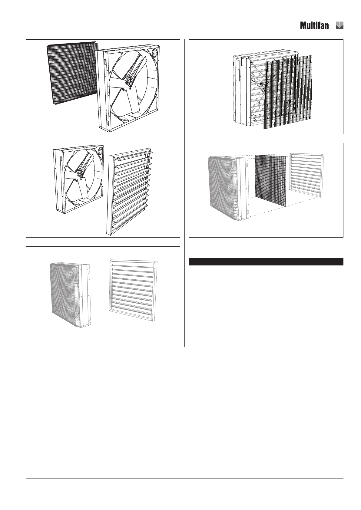
5.1 Overview .......................................................................................4
5.2 Options ..........................................................................................4
5.3 Identification of the product ...........................................................5
5.4 Intended use..................................................................................7
5.5 Technical information ....................................................................7
5.6 Other information...........................................................................7
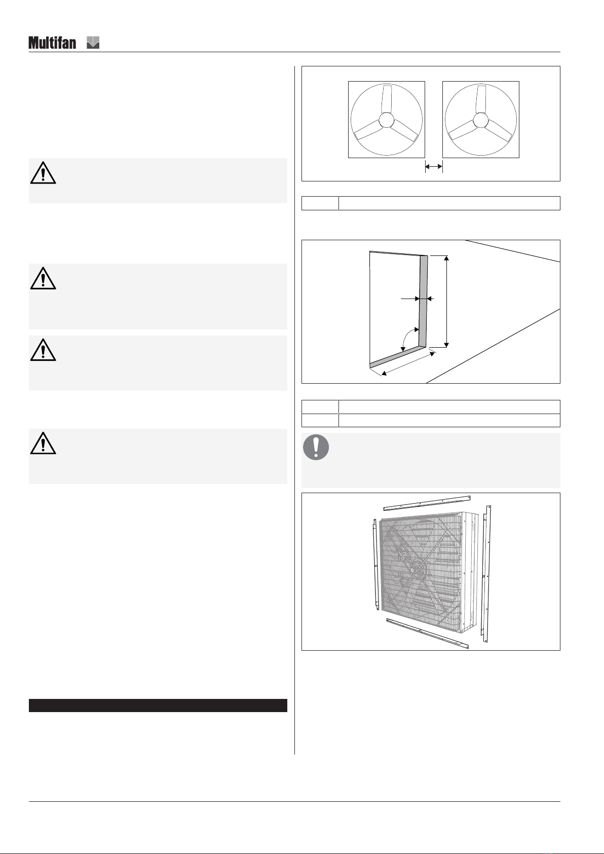
6 Installation .............................................................................................7
6.1 Mechanical ....................................................................................8
6.2 Electrical........................................................................................9
6.2.1 Thermal protection........................................................11
6.2.2 Speed control ...............................................................11
7 Commissioning ...................................................................................11
8 Operation .............................................................................................12
9 Maintenance.........................................................................................12
9.1 Maintenance schedule ................................................................12
9.2 Maintenance subjects..................................................................12
10 Troubleshooting and repairs..............................................................13
11 End of life.............................................................................................14
12 EU Declaration of Conformity ............................................................14
Glossary...............................................................................................15
1 Introduction
Thank you for choosing this Galvanized Box Fan 130.
IMPORTANT: READ THESE INSTRUCTIONS CAREFULLY BEFORE USE
KEEP THESE INSTRUCTIONS FOR FUTURE REFERENCE
LIRE ET CONSERVER CES INSTRUCTIONS
These instructions are a part of this fan and must be passed on to any
subsequent owner and/or user.
Contact your supplier if there are parts of these instructions that you do not
understand. Compliance with these instructions will ensure a safe and correct
use of this fan.
NOTICE
This fan is for industrial, commercial and professional use
only.
Packaging
If packaging materials are no longer required, dispose of them in accordance
with regulations that apply in your area.
Modification of this fan
Modifying this fan without written permission of Vostermans Ventilation B.V. is
not permitted.
Warranty will be void when this fan is modified without permission.
The EU Declaration of Conformity is no longer valid if this fan is modified
without permission.
Legal notice / Disclaimer
The scope of delivery may vary from product images shown. This document
was created with all due care. The information, instructions and parts listed
are current on the date this document was issued.
Improper use
No liability is accepted for damages resulting from improper use.
2 Safety
Safety messages
Your safety and the safety of others are very important. Important safety
messages are provided in these instructions.
READ THESE MESSAGES CAREFULLY
A safety message alerts you to potential hazards that could hurt you or
others. Each safety message is preceded by a safety symbol and one of four
signal words: DANGER, WARNING, CAUTION or NOTICE.
Explanation of the signal words used in this document
DANGER : You will be killed or seriously hurt if you do not follow instructions.
WARNING : You can be killed or seriously hurt if you do not follow
instructions.
CAUTION : You can be hurt if you do not follow instructions.
NOTICE : Is used to address practices not related to physical injury.
Explanation of the safety symbols used
General warning symbol
Warning for electricity
Warning for hot surfaces
Warning for sharp elements
Warning for automatic activation
Warning for explosive materials
General mandatory action sign
Remark: not all of the listed symbols may be used in this document

Galvanized Box Fan 130
INS00025-A Original instructions ENGLISH | 3
3 Safety instructions
WARNING
To reduce the risk of fire, electric shock, or injury to persons,
observe the following:
• Use this unit only in the manner intended by the manufacturer. If you
have questions, contact the manufacturer.
• Before servicing or cleaning unit, switch power off at service panel and
lock the service disconnecting means to prevent power from being
switched on accidentally. When the service disconnecting means cannot
be locked, securely fasten a prominent warning device such as a tag, to
the service panel.
CAUTION
For General Ventilating Use Only. Do Not Use To Exhaust Haz-
ardous Or Explosive Materials And Vapors
All personnel must read and follow every instruction in this manual. It is the
responsibility of the employer to make sure that this is followed. If you are not
sure about the safety procedures, please refer to local legal legislation or the
safety officer of your company.
More specified safety procedures - legal, local or from your company - can be
applicable when the fan is in operation. This manual does not supply these
procedures. This manual only gives all necessary information about the fan
itself.
Most fans have a sound pressure level of less than 70 dB(A) at 50Hz / 60Hz.
Values for specific machines will be found in the relevant technical
specifications.
Follow the following safety instructions:
• Keep limbs, long hair and loose clothing away from rotating parts.
• When you assemble the fan, always follow the instructions supplied in
this manual.
• It is not permitted to stop or remove the safety precautions.
• Refer to section “Maintenance and Maintenance Schedule” for more in-
formation about when you must do the maintenance of the fan. No main-
tenance may decrease the safety of the fan.
• If the safety precautions are damaged, do not use the fan.
• If there is a malfunction, do not use the fan.
• Repair a damaged fan, before you put it in operation again.
There can be safety labels on the fan. You must put new safety labels on the
fan if:
• You cannot read the text or symbols clearly.
• A label is damaged.
Contact your supplier to order new safety labels.
WARNING
Install a wire guard if you install the fan below a height of 2,7m.
Make sure that it is installed in a stable position.
Personnel
This manual refers to different types of personnel. Each type of personnel has
different tasks and responsibilities.
The types of personnel are:
• Operators
• Maintenance personnel
Operators
Only let adults operate this fan. All operators must know and follow the
procedures in this manual. No special education is necessary to operate this
fan.
Each operator must perform these tasks:
• Operate the fan.
• Monitor the correct operation of the fan.
Maintenance personnel
Maintenance personnel must know the risks of their tasks. All maintenance
personnel can do the tasks of an operator.
Also, all maintenance personnel must have:
• A technical education background (at least a Secondary Vocational Edu-
cation).
• Experience with the maintenance and assembly of fans.
Maintenance personnel must perform these tasks:
• Assembly of the fan.
• Maintenance of the fan.
Personal Protective Equipment
CAUTION
Wear safety gloves and safety glasses during maintenance of
the fan.

Galvanized Box Fan 130
4 | ENGLISH Original instructions INS00025-A
4 Assembly
This product is supplied either assembled or unassembled depending on how
it was ordered.
NOTICE
Assembly must be carried out by skilled persons
Before commencing assembly, check that nothing has been damaged during
transport.
When this product is supplied unassembled, the assembly instructions are
supplied separately and are part of these instructions.
CAUTION
Some parts may have sharp edges
Risk of cuts
5 Information
5.1 Overview
1 Intake guard
2 Motor and motor rating plate
3 Fan housing
4 Impeller
5 Shutter
The number and type of fan blades in the impeller in your fan may vary from
illustrations shown in this document.
10NR-3 12BR-3 12BR-6
Illustration1: Possible impeller models used in this fan series
5.2 Options
This Galvanized Box Fan 130 can be delivered with one of more of the
following options. The assembly instructions of the options are supplied
separately and are part of these instructions.
Illustration2: Wall mounting set
Illustration3: Cone
Illustration4: Wire guard on the air outlet

Galvanized Box Fan 130
INS00025-A Original instructions ENGLISH | 5
Illustration5: Wire guard on the air inlet
Illustration6: Shutter on the air outlet
Illustration7: Shutter on the air inlet
Illustration8: Wire guard shutter on the air inlet
Illustration9: Shutter with wire guard on the air outlet
5.3 Identification of the product
A rating plate is permanently attached to the Galvanized Box Fan 130 and it
must not be removed.
The rating plate displays electrical, mechanical and identification information.
Each fan has a unique 14-digit numerical serial number which is listed on the
rating plate. The serial number must be provided in any future
correspondence regarding this fan as it is the unique information used for
identifying the fan in question.

Galvanized Box Fan 130
6 | ENGLISH Original instructions INS00025-A
Explanation type plates
1. Article number VV 25. Drip proof 49. µ At optimum
2. Serial number 26. IP class 50. Static pressure (0 Pa)

Galvanized Box Fan 130
INS00025-A Original instructions ENGLISH | 7
Explanation type plates
3. Wiring diagram 27. Insulation class 51. Air volume at 0 Pa (m3/h)
4. Voltage (V) 28. TEAO (Totally Enclosed Air Over) 52. Static pressure (x Pa)
5. Frequency (Hz) 29. Number of phases 53. Air volume at x Pa (m3/h)
6. Nominal current (A) 30. Manufacturers name 54. PSE-logo
7. Rotation speed (RPM) 31. Manufacturers address 55. Fan current (A)
8. Power (kW or PK) 32. Manufacturers country 56. Pressure at 0 inwg.
9. Cos phi 33. cURrus logo 57. Air volume at 0 inwg.CFM
10. Service factor 34. CE-logo 58. Pressure at –x- inwg.
11. Service factor ampere 35. CSA-logo 59. Air volume at –x- inwg.
12. Full load ampere 36. W333 bin 60. Max. ambient temperature °F
13. Capacitor (µF/V) 37. Tester code 61. Min. ambient temperature °F
14. Max. ambient temperature °C 38. Work order date 62. Order
15. Min. ambient temperature °C 39. Fan type 63. CCC-logo
16. IE2 40. Imax (A) 64. Motor data. For…..
17. µ 100% 41. P 65. House code
18. µ 75% 42. VSD used 66. Acceptable for field wiring
19. µ 50% 43. Part number customer 67. Min-1 application
20. Thermal protection (*) 44. Weight (kg) 68. Cos phi application
21. Year of construction 45. Controllability (**) 69. Wiring diagram application
22. Bar code 46. Energy efficiency category 70. QR code
23. Winding diagram 47, Energy efficiency static or total 71. Rotor code
24. Weather proof 48. µ Overall 72. EAC logo
*) Thermal protection (NC) (for single phase: 250V 10A cos Φ =1 / for 3-
phase: 250V 2.5A cos Φ =1)
**) E = suitable for electronic voltage control (TRIAC / phase cutting).
**) T = suitable for transformer voltage control.
**) F = suitable for frequency control / VFD (Variable Frequency Drive).
A frequency controller in combination with a single phase motor is possible.
A QR-code is displayed on the rating plate. This QR-code contains a link to
an information page about this product. Here you can find a digital copy of
these instructions as well as other information about this product.
5.4 Intended use
This Galvanized Box Fan 130 is intended to be used as an exhaust fan for the
mechanical ventilation of livestock houses (pigs, poultry, dairy) and
greenhouses or industrial applications.
NOTICE
This fan is intended for moving air only.
DANGER
Do not use this fan in explosive or potentially explosive atmo-
spheres.
5.5 Technical information
Sound pressure levels are measured at a distance of 2 meters and corrected
for the human ear (A-weighting) in dB(A). The technical datasheet contains
calculated sound pressure levels in dB(A) at a distance of 7 meters assuming
free field conditions.
Technical specifications regarding performances are guaranteed until 1000
meters above sea level.
For detailed technical information please visit our website from which
technical datasheets can be viewed and downloaded.
http://productselector.vostermans.com
5.6 Other information
DANGER
Ventilation system failure
This fan is manufactured to the highest quality standards. Neverthe-
less, failure of a fan can always occur.
This fan is intended to be used as a component of a ventilation sys-
tem. Where the health and well-being of humans and/or animals is
dependent on the functioning of this ventilation system, an appropri-
ate backup system must be provided such that in the event of failure
of the main system, sufficient air renewal is guaranteed to preserve
the health and well-being of the humans and/or animals.
An alarm system, which will operate even if the principal electricity
supply to it has failed, must be provided to give warning of any fail-
ure in the system.
6 Installation
WARNING
Installation must be carried out by skilled persons only!

Galvanized Box Fan 130
8 | ENGLISH Original instructions INS00025-A
►Before commencing installation
1. Check the fan after you have received it and make sure it has not been
damaged during transport.
2. Briefly rotate the impeller and/or motor shaft by hand to make sure they
rotate freely.
3. Check all the information on the rating plate and verify that this fan is
suitable for the intended application.
WARNING
Never install a damaged or incomplete fan.
• It is the installer’s responsibility that the installation and safety instruc-
tions are in accordance with current standards and regulations.
• Every fan has to be grounded according to the applicable standard.
• Do not use the fan as part of a construction
CAUTION
In case of speed regulation, the fan may vibrate when incor-
rectly mounted / installed. Check this before completing the in-
stallation.
CAUTION
The fan must always be installed or mounted in a stable way
before taking in operation.
USA-only
WARNING
To reduce the risk of fire, electric shock, or injury to persons,
observe the following:
• Installation work and electrical wiring must be done by qualified per-
son(s) in accordance with all applicable codes and Standards, including
fire-rated construction.
• Sufficient air is needed for proper combustion and exhausting of gases
through the flue (chimney) of fuel burning equipment to prevent back
drafting. Follow the heating equipment manufacturer's guideline and
safety Standards such as those published by the National Fire Protection
Association (NFPA), and the American Society for Heating, Refrigeration
and Air Conditioning Engineers (ASHRAE), and the local code authorit-
ies.
• When cutting or drilling into wall or ceiling, do not damage electrical wir-
ing and other hidden utilities.
• Ducted fans must always be vented to the outdoors.
Hose down
This fan is IP55 and can be hosed down with water. The installer is to use
rigid conduit or electrical metallic tubing with rain-tight fittings, or liquid-tight
flexible metal or non-metallic conduit with acceptable fitting.
6.1 Mechanical
Preparation
Before commencing the installation, plan the installation distance between the
fans properly.
X
Illustration10: Spacing between fans
X ≥100mm
The opening in the wall in which the fan will be installed must be square,
plumb and flat. The surface on which the fan rests must be flat.
A
BA
90°
Illustration11: Wall opening dimensions
A 1383mm
B >100mm
NOTICE
Do not use cement or expanding polyurethane foam to fix the
fan in the wall opening
Illustration12: Optionally available wall installation set
An installation set with four corner profiles is optionally available. With this set,
the fan can easily be mounted in the wall. Please contact your supplier for
more information.
Installation sequence
1. Install the fan in the wall opening.
ðInstall the fan with the electric motor in the correct position (top
right when viewed from exhaust side of the fan).

Galvanized Box Fan 130
INS00025-A Original instructions ENGLISH | 9
Illustration13: Motor position
ðDo not embed the shutter in the wall.
30 - 50mm
Illustration14: Do not embed the shutter in the wall
ðMake sure that the fan protrudes far enough from the wall so that
the drain holes are not blocked by the wall.
2. Open the knockout drain holes in the bottom housing part. Water that will
enter the housing during e.g. cleaning can drain away.
Illustration15: Fan housing drain holes
Guarding
NOTICE
The fan must be guarded according to local regulations
Illustration16: Optionally available guard
Default, the fan is delivered with a guard on the intake side. The shutter acts
as a guard for the exhaust side, but does not provide the required safety
distances to prevent hazard zones being reached by upper and lower limbs
(ISO 13857:2008). Depending on installation height or location, the shutter
may therefore not provide the required level of protection. A guard for in
between the shutter and fan housing is optionally available. Please contact
your supplier for more information.
Condensate drain holes
The fan motor has drain holes to allow condensation that may form inside the
motor to leave the motor. After installation, the drain hole at the lowest point
of the motor must be open, the other drain holes must be closed.
Spare condensate drain plugs are supplied with the fan. Keep all the drain
plugs as they must be temporarily reinserted in the open drain holes during
wet cleaning.
Illustration17: Condensate drain plug
6.2 Electrical
Wiring diagrams
NOTICE
Electrical connection must be carried out by a qualified electri-
cian. Electrical connections must be made in accordance with
local regulations.
Check the rating plate and verify that this fan is suitable for the available
power supply.
For 3~ fan motors: check that STAR / DELTA is properly configured on the
terminal block.
CAUTION!In case your fan motor is supplied pre-wired with
a power cable, still always check the terminal block or the
luster terminal configuration.

Galvanized Box Fan 130
10 | ENGLISH Original instructions INS00025-A
L N
1~
AA
TB
Illustration18: 1~
L1 N / L2
1~
AA US
TB
Illustration19: 1~ (North America)
For 3~ fans, depending on the motor model used in your fan either a terminal
block or a luster terminal is present.
L1 L2 L3
3~ 3~
L1 L2 L3
AB03 AB04
AB01 AB02
Illustration20: 3~ STAR / DELTA (standard terminal block)
3~
3~
AC
TB
TB
L1 L2 L3
TB
TB
L1 L2 L3
Illustration21: 3~STAR / DELTA with optional thermal detectors (thermostats)
yellow
ged
grey
brown
purple
blue
yellow
blue
red
grey
brown
pruple
AF01
AF02
L1 L2 L3
L1 L2 L3
Illustration22: 3~ STAR / DELTA – counterclockwise rotation
NOTICE! STAR is for HIGH voltage / DELTA is for LOW
voltage
Control
This fan is supplied without a control or control system. You can use a control
or a control system for operation of the fan.
Isolator
This fan is supplied without an electrical isolator (supply disconnecting
(isolating) device). An electrical isolator must be provided to facilitate safe
maintenance and troubleshooting.
Grounding
The fan must be grounded. Ground the fan according to local
regulations.
NOTICE
Overcurrent protection
The use of an individual separate overcurrent protective device per
fan is highly recommended.
NOTICE
Overload protection
The use of an individual separate overload protective device (Motor
Protective Circuit Breaker) per fan is highly recommended.

Galvanized Box Fan 130
INS00025-A Original instructions ENGLISH | 11
6.2.1 Thermal protection
1~ fan motor thermal protection
Thermal protectors are built-in standard in 1~ fan motors. Thermal protectors
are of the thermostat type TB: thermostat opening on increase of
temperature.
In 1~ fan motors, the thermostat (TB) is by default wired in series with the
phase (L) of the supply. The motor is as such self-resetting: when the motor
overheats, the thermostat will switch off the motor automatically and once the
motor has cooled down, the motor will start automatically again.
The presence of the text “Thermally Protected” on the rating plate and/or
datasheet indicates that thermal protection is built-in the 1~ fan motor and that
it is wired in series with the phase (L) of the supply.
WARNING
If the unexpected start of the motor by the thermostat can
cause a hazard or is prohibited by local regulations, the ther-
mostat must be connected into a control circuit that will not al-
low the motor to restart until the circuit is manually reset.
3~ fan motor thermal detection (optionally available)
Thermal detectors are optionally available in 3~ fan motors. Thermal
detectors are of the thermostat type TB: thermostat opening on increase of
temperature.
In 3~ fan motors, the thermostats (TB) are by default wired to separate
terminals on the terminal block. An external control circuit can be connected
here. NOTICE! The thermostats in 3~ fan motors cannot be
wired in series with the power supply.
Maximum load for the thermostat (TB)
VAC: maximum 500 V
IAC: maximum 1.6 A
Cos Φ: minimum 0.6
Maximum number of switching cycles: 1000
VDC: maximum 12 V
IDC: maximum 40 A
Maximum number of switching cycles: 1000
6.2.2 Speed control
Verify that this fan is suitable for speed control. On the datasheet and rating
plate the following (combination of) codes can be found:
FC = suitable for frequency control / VFD (Variable Frequency Drive)
E = suitable for electronic voltage control (TRIAC / phase cutting)
T = suitable for transformer voltage control
WARNING
If none of these codes is listed, this fan cannot be speed con-
trolled!
Variable Frequency Drive (FC / frequency control)
• Do not reduce the frequency to less than 20% of the nominal frequency
as listed on the rating plate.
• When using a variable frequency drive, the wiring instructions of the vari-
able frequency drive manufacturer must be followed.
WARNING
Do not increase the frequency beyond the nominal value as lis-
ted on the rating plate
Electronic Voltage Control (TRIAC / SOLID-STATE / phase
cutting)
• Do not reduce the voltage to less than 40% of the nominal voltage as lis-
ted on the rating plate.
• Motor noise (humming) can occur due to this type of control
Transformer voltage control
• Do not reduce the voltage to less than 40% of the nominal voltage as lis-
ted on the rating plate.
For US only:
For 3~ fans only:
WARNING
To Reduce The Risk of Fire or Electric Shock, Do Not Use This
Fan With Any Solid-State Speed Control Device
For Canada only:
For 3~ fans only:
WARNING
NOT SUITABLE FOR USE WITH SOLID-STATE SPEED CON-
TROLS
AVERTISSEMENT: NE CONVENIENT PAS À DES REGU-
LATEURS DE VITESSE A SEMI-CONDUCTEURS.
7 Commissioning
1 Air flow direction
2 Impeller rotation direction
Before initial start-up verify that:
1. Installation and electrical connection have been properly completed.
2. No foreign material is present within the fan and fan housing.
3. All necessary safety devices such as guards are in place.
Initial start-up
1. Briefly switch on the power supply and check if the impeller rotates in the
correct direction. Correct if necessary:
– For 3~ fans interchange any 2 of the 3 phases of the supply.
– For 1~ fans contact your supplier.

Galvanized Box Fan 130
12 | ENGLISH Original instructions INS00025-A
2. Run the fan and check for quiet (no unusual noises), low vibration opera-
tion. Check that the current draw is within the full load limits as listed on
the rating plate and datasheet.
3. Refer to the troubleshooting section of these instructions if anything
seems out of the ordinary.
8 Operation
Always be alert when the fan is in operation. Immediately switch off and
isolate the fan from the electrical supply if anything seems out of the ordinary.
Refer to the troubleshooting section of these instructions if anything seems
out of the ordinary.
DANGER
If the built-in thermal protection is in series with the power sup-
ply and is activated, the fan motor will automatically re-start
after cooling down.
Risk of injury due to unexpected start.
CAUTION
The fan motor can get hot during operation
Do not touch it to prevent burns
Infrequent use
If the fan is used less frequently than once per month, run the fan each month
at least 2 hours at full speed to avoid buildup of moisture in the fan motor and
to keep the bearing lubricant in good condition.
9 Maintenance
DANGER
Switch off and completely isolate the fan from the electrical
supply before commencing maintenance.
WARNING
All moving parts must be at a complete standstill before com-
mencing maintenance.
WARNING
Even when electrically isolated, fans may be subjected to free
spinning or „wind milling“. Secure the impeller physically to re-
strict rotational movemenent where this poses a risk.
• All safety and work regulations have to comply to the current standards.
• All work has to be carried out by qualified personnel.
• When you remove safety devices such as guards for maintenance, you
must install these safety devices after maintenance.
9.1 Maintenance schedule
►Maintenance tasks – TO BE CARRIED OUT EVERY MONTH
1. Examine the fan housing for defects and remove any dirt that has accu-
mulated.
2. Examine the motor and remove any dirt that has accumulated on the
motor and between the motor cooling fins.
3. Examine the impeller for defects and remove any dirt that has accumu-
lated.
4. Examine the condition of the guards (if fitted) and remove any dirt that
has accumulated.
5. Examine the shutter for defects and remove any dirt that has accumu-
lated.
►Maintenance tasks – TO BE CARRIED OUT EVERY 3 MONTHS
1. Check the condition of the bearings.
2. Check the tightness of fasteners and fixings.
►Maintenance tasks – TO BE CARRIED OUT ANNUALLY
1. Only for 1~ fan motors: check the capacitor capacitance.
9.2 Maintenance subjects
Cleaning
In areas of application where high levels of contamination are present,
cleaning intervals should be adjusted accordingly.
Cleaning is preferably done using a soft brush. Do not use any aggressive
detergents, solvents or chemicals for cleaning.
Wet cleaning
Wet cleaning is allowed using low pressure clean water spray. Avoid directing
water jets at bearings and electrical connections as much as possible.
When wet cleaning is planned, close any open condensate drain holes before
commencing wet cleaning.
WARNING
Do not use a high pressure cleaner.
Water may penetrate electrical connections and bearings.
►After wet cleaning
1. Open the condensate drain hole at the lowest point of the fan motor.
2. Run the fan for 2 hours at full speed to remove any moisture that may
have entered the fan motor.
Bearings
The bearings used in the fan and/or fan motor are maintenance free and
greased for life. Average lifespan during normal operation is >30.000 hours.
Defects in the bearings can usually be detected by listening. When the shaft /
impeller is rotated by hand, it should move freely with a smooth uniform
sound. Squeaking or grinding noises indicate the bearings may require
replacement.
Impeller
Cleaning the impeller is very important. A dirty impeller will suffer from
imbalance resulting in vibrations. A dirty impeller will also result in reduced fan
performance and reduced fan efficiency.
V-belt tension check
►Simple method to check proper V-belt tension
1. Measure span length A
2. Calculate deflection length C
ðC = 0.0156 x A (mm)
ðPushing with deflection force B, deflection should be C
Deflection force B:
V-belt profile: A Deflection force B (kg)
Small pulley Ø (mm) Min Max
75 to 90 1.6 2.4
90 to 118 2.0 2.8
118 to 180 2.3 3.3

Galvanized Box Fan 130
INS00025-A Original instructions ENGLISH | 13
A
A
B
C
1
2
Illustration23: V-belt tension check
Adjusting the V-belt tension
The V-belt tension in this fan can be adjusted by adjusting the mounting
position of the motor.
Illustration24:
1. Loosen the bolts (1)
2. Tighten the bolts (2) until the required V-belt tension has been reached
3. Fasten the bolts (1) again
Capacitor (1~ fan motor)
Capacitor capacitance decreases slowly over time. Average lifespan is ±
30.000 hours. Replace the capacitor when the capacitance has dropped
below the value as listed on the capacitor.
Start capacitor (1~ fan motor)
The start capacitors’ lifespan is 500.000 starts. Replace the start capacitor
when the number of starts has reached 500.000.
The start capacitor cannot be serviced or repaired. The start capacitor must
be replaced if it is not functioning properly anymore.
Louvre shutter
Cleaning the shutter is very important. A dirty shutter will reduce the amount
of air moved by the fan reducing your fan efficiency. Clean the louvres
carefully to avoid bending or damaging them. Damaged louvres can cause
the shutter to leak.
10 Troubleshooting and repairs
WARNING
Troubleshooting and repairs must be performed by skilled per-
sons only!
Fault Possible cause Possible remedy
Airflow too high Fan speed (rpm) too high Check supply voltage and frequency
System resistance lower than specified Reduce fan speed (if fan can be speed controlled)
Choose alternative fan
Airflow too low System resistance higher than specified Choose alternative fan
Lower system resistance
Excessive vibration Impeller imbalance -> impeller damaged Replace impeller
Impeller imbalance -> impeller dirty Clean impeller
Bearings damaged or worn Replace bearings
Fan does not start No power supplied to fan Check all power supplies
Check fuse/circuit breaker
Check the cabling
Switch on controller
(If present) VFD (Variable Frequency Drive) defect-
ive
Check VFD (refer to VFD manufacturers’ instruc-
tions)
Fan does not start
(supply voltage at fan motor terminals is present)
Thermal protection activated
(Fan motor has overheated)
Clean motor
Check for overloading of fan system (intake or ex-
haust blocked?)
Check if supply voltage is not too high or too low
Impeller blocked Remove blockage
Only for 1~ fan motors: wrong or defective capacitor Replace capacitor
Temperature too low for bearing grease Do not operate fan outside ambient temperature
range as specified on rating plate and technical data
sheet
Fan motor overheats while running Fan overloaded Check for overloading of fan system (intake or ex-
haust blocked?)
Fan motor overheated due to dirt in cooling fins. Clean fan motor

Galvanized Box Fan 130
14 | ENGLISH Original instructions INS00025-A
Fault Possible cause Possible remedy
Supply voltage too high or too low Check power supply
Incorrect supply frequency Check power supply
Bearings damaged or worn Replace bearings
Only for 3~ motors: phase voltage imbalance Check power supply
Only for 3~ motors: STAR instead of DELTA con-
nected or DELTA instead of STAR connected
Check wiring diagram
Connect correctly
Only for 1~ motors: wrong or defective capacitor Replace capacitor
Fan motor overheats while running Only for 1~ fan motors with start capacitor: Start ca-
pacitor does not disengage after motor has started
(continuously on)
Replace start capacitor
Fan rotates in wrong direction 1~ fan motors: capacitor incorrectly connected Connect according to wiring diagram (contact sup-
plier)
3~ fan motors: supply incorrectly connected Swap any 2 of the 3 phases of the supply
Fan speed (rpm) is too low Supply voltage too low Check power supply
Incorrect supply frequency Check power supply
Only for 1~ fans: wrong or defective capacitor Replace capacitor
Only for 3~ fans: STAR instead of DELTA connec-
ted
Connect as DELTA
Check wiring diagram!
3~fan motors: Phase failure Restore all 3 phases
Fan speed (rpm) is too low Belt not tight enough Adjust the tension of the belt or replace the belt
High power consumption Fan overloaded Check for overloading of fan system (intake or ex-
haust blocked?)
Fan speed too high Check supply voltage and frequency
Bearings damaged or worn Replace bearings
Unusual or excessive noises Impeller hits fan housing Check installation and fixings and alignment
Fan is operating in stall point Lower system resistance
(Intake or exhaust blocked)
Bearings damaged or worn Replace bearings
Unusual or excessive noises Only for 1~ motors with start capacitor: Start capa-
citor does not disengage after motor has started
(continuously on)
Replace start capacitor
Use original spare parts only.
11 End of life
Disposal
At the end of the life of this fan, dispose of it properly in accordance with
regulations that apply in your area.
NOTICE
Always sort and recycle waste.
Recycling
The main materials used in the electric motor are copper, steel and
aluminium.
Most of the fan parts have the recycling symbol with material code listed on
them to facilitate proper recycling. Some parts are made of easy to identify
materials such as steel, and have no recycling symbol on them.
Symbol Material
Polypropylene
ABS (Acrylonitrile butadiene styrene)
Polyamide
Glass fibre reinforced polypropylene
Aluminium
12 EU Declaration of Conformity
EU Declaration of Conformity
(according to Annex II.1.A. of the machinery directive 2006/42/EC)
The manufacturer: Vostermans Ventilation B.V.

Galvanized Box Fan 130
INS00025-A Original instructions ENGLISH | 15
Visiting address: Industrial Zone Venlo 5082
Parlevinkerweg 54
NL-5928 NV Venlo
The Netherlands
Postal address: P.O. Box 3025
NL-5902 RA Venlo
The Netherlands
Telephone: +31 (0) 77 389 32 32
Fax: +31 (0) 77 382 08 93
Internet: www.vostermans.com
E-mail: [email protected]
declares under sole responsibility that the following machineries:
Name / description: Galvanized Box Fan 130
Article numbers starting with: V4D13, V4E13
are in conformity with the relevant Union harmonisation legislation and fulfil all
the relevant provisions of the following directives and regulations:
2006/42/EC (including modifications) 2012/19/EU (including modifications)
2014/30/EU (including modifications) (EU) No 327/2011
2011/65/EU (including modifications)
on which the following harmonised standards were used:
EN ISO 12100:2010 EN 61800-3:2004/A1:2012
EN 60204-1:2006/AC:2010 EN 50581:2012
EN ISO 13857:2008 EN ISO 11201:2010
EN 349:1993/A1:2008 EN ISO 11203:2009
EN ISO 14120:2015 EN ISO 11204:2010
EN 61000-6-2:2005/AC:2005 EN ISO 13732-1:2008
EN 61000-6-4:2007/A1:2011
and on which the following other technical standards and specifications were
used:
ISO/TR 14121-2:2012 EN 61800-3:2018
EN 60204-1:2018 EN 63000:2018
EN ISO 13857:2019 EN ISO 5801:2017
EN ISO 13854:2019 EN ISO 12499:2009
EN 61000-6-2:2019 IS0 13348:2007
EN 61000-6-4:2019 ISO 9001:2015
Signed for and on behalf of: Vostermans Ventilation B.V.
Place: Venlo – The Netherlands
Date: 2020/02/20
Identities and signatures:
P.W. Provó Kluit, R&D Manager
(authorised to compile the technical file)
H.L.J. Vostermans, C.E.O.
(Fan pro – DoC 2006_42_EC – v2.4 en)
Glossary
Explosive atmosphere
A mixture of air, under atmospheric conditions, with flammable sub-
stances in the form of gases, vapours, mists or dusts in which, after igni-
tion has occurred, combustion spreads to the entire unburned mixture.

Venlo - The Netherlands
Tel. +31 (0)77 389 32 32
www.vostermans.com
Bloomington, IL- USA
Tel. +1 309 827-9798
Tmn Klang Jaya - Malaysia
Tel. +60 (0)3 3324 3638
Shanghai - China
Tel. +86 21 5290 2889/2899
00/0000
is a brand of Vostermans Ventilation B.V.
DocumentID: INS00025-A
Created: 28/05/2020 *INS00025*
Other manuals for 130
1
Table of contents
Other Multifan Fan manuals