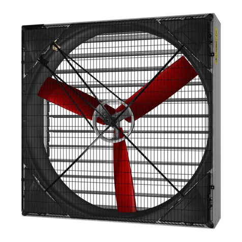
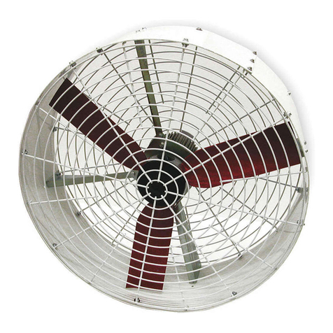
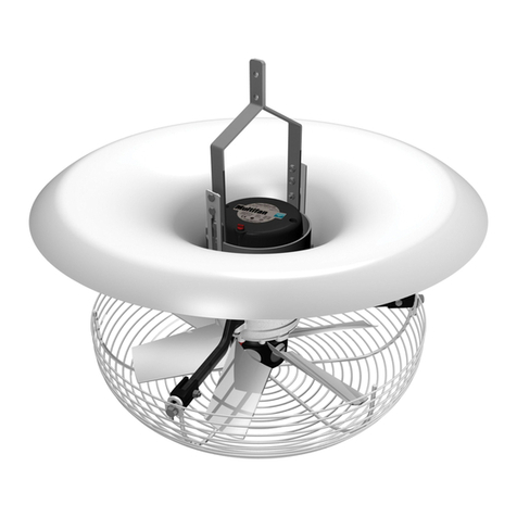
Multifan VP0024 Parts list manual

Tube Fan
Tube Fan
Tube Fan
Tube Fan
ENGLISH
Installation Instructions - Operating Instructions
NEDERLANDS
Installatie Instructies - Gebruiksaanwijzing
DEUTSCH
Installationsanleitung - Betriebsanleitung
FRANÇAIS
Instructions d'installation - Mode d'emploi
Document ID: INS00062-B
IMPORTANT - READ CAREFULLY BEFORE USE
BELANGRIJK - VOOR GEBRUIK ZORGVULDIG LEZEN
WICHTIG - VOR GEBRAUCH SORGFÄLTIG LESEN
IMPORTANT - LIRE ATTENTIVEMENT AVANT UTILISATION

Table of Contents
English.................................................................................................................................... 5
Nederlands.............................................................................................................................. 14
Deutsch................................................................................................................................... 24
Français.................................................................................................................................. 34
2 INS00062-B

A
FAN ASSEMBLY
1x B
BVVP0019
3x C
BZKM6X30RVS
3x D
ZBM6RVS
3x
M8
8mm
120°
Installation in duct
3
Tube Fan
INS00062-B

VP0024
VP0078
VP0080
VP0063
VP0064
Ø D
Ø D
X
14.5 mm
14.5 mm
= Ø D - (2 x 14,5mm)
B
A
X = D/2 - 185.5 -14.5 mm
X = D/2 - 178 -14.5 mm
11 mm
9 mm
Ø 10 mm
11 mm
9 mm
Ø 10 mm
14.5 mm
14.5 mm
Motor support length
4
Tube Fan
INS00062-B

Tube Fan
INS00062-B Original instructions ENGLISH | 5
Table of Contents
1 Introduction ...........................................................................................5
2 Safety...................................................................................................... 5
3 Information.............................................................................................6
3.1 Overview .......................................................................................6
3.2 Intended use..................................................................................6
3.3 Technical information ....................................................................6
3.4 Other information...........................................................................6
4 Assembly ...............................................................................................6
5 Installation .............................................................................................6
5.1 Mechanical ....................................................................................6
5.2 Electrical........................................................................................7
5.2.1 Thermal protection..........................................................8
5.2.2 Speed control .................................................................8
6 Commissioning .....................................................................................8
7 Operation ...............................................................................................8
8 Maintenance...........................................................................................9
8.1 Maintenance schedule ..................................................................9
8.2 Maintenance subjects....................................................................9
9 Troubleshooting and repairs................................................................9
10 End of life............................................................................................. 10
11 EU Declaration of Incorporation ........................................................11
Glossary............................................................................................... 13
1 Introduction
IMPORTANT: READ THESE INSTRUCTIONS CAREFULLY BEFORE USE
KEEP THESE INSTRUCTIONS FOR FUTURE REFERENCE
These instructions are a part of this fan and must be passed on to any
subsequent owner and/or user.
Contact your supplier if there are parts of these instructions that you do not
understand. Compliance with these instructions will ensure a safe and correct
use of this fan.
Target groups
General
These instructions are intended for:
• Installers tasked with the assembly (if applicable) and/or mechanical in-
stallation of this fan.
• Electricians tasked with the electrical installation of this fan.
• Operators tasked with the operation of this fan.
• Maintenance technicians tasked with maintenance and troubleshooting
of this fan.
Target group requirements:
• Installers must have sufficient relevant experience or training in the in-
stallation of this type of fans.
• Electricians must be qualified electricians.
• Operators must have sufficient relevant experience or training in operat-
ing this type of fans.
• Maintenance technicians must have sufficient relevant experience or
training in maintaining and troubleshooting this type of fans.
NOTICE
This fan is for professional, industrial or commercial use only.
Packaging
If packaging materials are no longer required, dispose of them in accordance
with regulations that apply in your area.
Modification of this fan
Modifying this fan without written permission of Vostermans Ventilation B.V. is
not permitted.
Warranty will be void when this fan is modified without permission.
Legal notice / Disclaimer
The scope of delivery may vary from product images shown. This document
was created with all due care. The information, instructions and parts listed
are current on the date this document was issued.
Improper use
No liability is accepted for damages resulting from improper use.
2 Safety
Safety messages
Your safety and the safety of others are very important. Important safety
messages are provided in these instructions.
READ THESE MESSAGES CAREFULLY
A safety message alerts you to potential hazards that could hurt you or
others. Each safety message is preceded by a safety symbol and one of four
signal words: DANGER, WARNING, CAUTION or NOTICE.
Explanation of the signal words used in this document
DANGER : You will be killed or seriously hurt if you do not follow instructions.
WARNING : You can be killed or seriously hurt if you do not follow
instructions.
CAUTION : You can be hurt if you do not follow instructions.
NOTICE : Is used to address practices not related to physical injury.
Explanation of the safety symbols used
General warning symbol
Warning for electricity
Warning for hot surfaces
Warning for automatic activation
Warning for explosive materials
General mandatory action sign
Remark: not all of the listed symbols may be used in this document

Tube Fan
6 | ENGLISH Original instructions INS00062-B
3 Information
3.1 Overview
1 Impeller
2 Duct mounting wall support
3 Motor support
4 Fan rating plate and terminal housing cover
Pictures used in this instruction may deviate from your actual product as
various motor and impeller models are used in this fan series.
Identification of the product
A rating plate is permanently attached to the Tube Fan and it must not be
removed.
The rating plate displays electrical, mechanical and identification information.
Each fan has a unique 14-digit numerical serial number which is listed on the
rating plate. The serial number must be provided in any future
correspondence regarding this fan as it is the unique information used for
identifying the fan in question.
A QR-code is displayed on the rating plate. This QR-code contains a link to
an information page about this product. Here you can find a digital copy of
these instructions as well as other information about this product.
3.2 Intended use
This partially completed fan is intended to be used as a component of a
ventilation system. This partially completed fan is intended to be installed in a
ventilation duct.
Illustration1: installation in duct
NOTICE
This fan is intended for moving air only.
DANGER
Do not use this fan in explosive or potentially explosive atmo-
spheres.
3.3 Technical information
For detailed technical information please visit our website from which
technical datasheets can be viewed and downloaded.
http://productselector.vostermans.com
3.4 Other information
DANGER
Ventilation system failure
This fan is manufactured to the highest quality standards. Neverthe-
less, failure of a fan can always occur.
This fan is intended to be used as a component of a ventilation sys-
tem. Where the health and well-being of humans and/or animals is
dependent on the functioning of this ventilation system, an appropri-
ate backup system must be provided such that in the event of failure
of the main system, sufficient air renewal is guaranteed to preserve
the health and well-being of the humans and/or animals.
An alarm system, which will operate even if the principal electricity
supply to it has failed, must be provided to give warning of any fail-
ure in the system.
4 Assembly
This fan is shipped either assembled or in parts. Assembly instructions to
assemble the fan are shipped with the unassembled fans.
5 Installation
►Before commencing installation
1. Check the fan after you have received it and make sure it has not been
damaged during transport.
2. Briefly rotate the impeller and/or motor shaft by hand to make sure they
rotate freely.
3. Check all the information on the rating plate and verify that this fan is
suitable for the intended application.
5.1 Mechanical
The fan must be installed into the ventilation duct using the duct wall
mounting supports provided. The duct wall mounting supports are designed to
accommodate a metric M8 bolt head for easy fastening of the duct wall
mounting support to the duct.
WARNING!The motor supports must always be secured in
the duct wall mounting supports with the bolts and nuts
provided.
Pictured in the front of these instructions is how to install the fan into the
ventilation duct. [}See also page3]

Tube Fan
INS00062-B Original instructions ENGLISH | 7
Motor support length
As the exact duct inner diameter is not always known upon ordering, certain
models are shipped with full length motor supports. The motor supports must
be cut to the correct length, for the fan to fit in the ventilation duct. Pictured in
the front of these instructions is how to cut the motor supports to the correct
length. [}See also page4]
For motor supports marked with VP0024, VP0078 or VP0080:
• Determine X and cut the motor support to the correct length
For motor supports marked VP0063 or VP0064:
• The numerical markings on the motor supports, are the inner diameter of
the duct in cm, minus the clearance needed for the motor supports to fit
in the duct wall mounting support.
• For example, if the duct inner diameter is 600mm, then cut the motor
support at the marking “60”. The fan will then fit in the duct mounting wall
supports.
After cutting the motor supports to length, drill a 10mm hole as indicated, so
that the motor supports can be fastened in the duct wall mounting support.
Installation positions
This fan can be installed in any orientation.
NOTICE! Always install the fan with the condensate drain
holes at the lowest possible position.
When installing the fan horizontally, always install the fan as such that the
condensate drain holes are at the lowest possible position.
Illustration2: Tube Fan Horizontal installation position
Condensate drain holes
The fan motor has drain holes to allow condensation that may form inside the
motor to leave the motor. After installation, the drain hole at the lowest point
of the motor must be open, the other drain holes must be closed.
Spare condensate drain plugs are supplied with the fan. Keep all the drain
plugs as they must be temporarily reinserted in the open drain holes during
wet cleaning.
Illustration3: Condensate drain plug
5.2 Electrical
Wiring diagrams
NOTICE
Electrical connection must be carried out by a qualified electri-
cian. Electrical connections must be made in accordance with
local regulations.
Check the rating plate and verify that this fan is suitable for the available
power supply.
For 3~ fan motors: check that STAR / DELTA is properly configured on the
terminal block.
L N
1~
AA
TB
Illustration4: 1~
L1 L2 L3
3~ 3~
L1 L2 L3
AB03 AB04
AB01 AB02
Illustration5: 3~ STAR / DELTA (standard terminal block)
3~
3~
AC
TB
TB
L1 L2 L3
TB
TB
L1 L2 L3
Illustration6: 3~STAR / DELTA with optional thermal detectors (thermostats)
Control
This fan is supplied without a control or control system. A control or a control
system must be provided for operation of the fan.
Isolator
This fan is supplied without an electrical isolator. An electrical isolator must be
provided to facilitate safe maintenance and troubleshooting.

Tube Fan
8 | ENGLISH Original instructions INS00062-B
Grounding
The fan must be grounded. Ground the fan according to local
regulations.
NOTICE
Overcurrent protection
The use of an individual separate overcurrent protective device per
fan is highly recommended.
NOTICE
Overload protection
The use of an individual separate overload protective device (Motor
Protective Circuit Breaker) per fan is highly recommended.
5.2.1 Thermal protection
1~ fan motor thermal protection
Thermal detectors are built-in standard in 1~ fan motors. Thermal detectors
are of the thermostat type TB: thermostat opening on increase of
temperature.
In 1~ fan motors, the thermostat (TB) is by default wired in series with the
phase (L) of the supply. The motor is as such self-resetting: when the motor
overheats, the thermostat will switch off the motor automatically and once the
motor has cooled down, the motor will start automatically again.
The presence of the text “Thermally Protected” on the rating plate and/or
datasheet indicates that thermal protection is built-in the 1~ fan motor and that
it is wired in series with the phase (L) of the supply.
WARNING
If the unexpected start of the motor by the thermostat can
cause a hazard or is prohibited by local regulations, the ther-
mostat must be connected into a control circuit that will not al-
low the motor to restart until the circuit is manually reset.
3~ fan motor thermal protection (optionally available)
Thermal detectors are optionally available in 3~ fan motors. Thermal
detectors are of the thermostat type TB: thermostat opening on increase of
temperature.
In 3~ fan motors, the thermostats (TB) are by default wired to separate
terminals on the terminal block. An external control circuit can be connected
here. NOTICE! The thermostats in 3~ fan motors cannot be
wired in series with the power supply.
5.2.2 Speed control
Verify that this fan is suitable for speed control. On the datasheet and rating
plate the following (combination of) codes can be found:
F = suitable for frequency control / VFD (Variable Frequency Drive)
E = suitable for electronic voltage control (TRIAC / phase cutting)
T = suitable for transformer voltage control
WARNING
If none of these codes is listed, this fan cannot be speed con-
trolled!
Variable Frequency Drive (FC / frequency control)
• Do not reduce the frequency to less than 20% of the nominal frequency
as listed on the rating plate.
• When using a variable frequency drive, the wiring instructions of the vari-
able frequency drive manufacturer must be followed.
WARNING
Do not increase the frequency beyond the nominal value as lis-
ted on the rating plate
Electronic Voltage Control (TRIAC / SOLID-STATE / phase
cutting)
• Do not reduce the voltage to less than 40% of the nominal voltage as lis-
ted on the rating plate.
• Motor noise (humming) can occur due to this type of control
Transformer voltage control
• Do not reduce the voltage to less than 40% of the nominal voltage as lis-
ted on the rating plate.
6 Commissioning
Before initial start-up verify that:
1. Installation and electrical connection have been properly completed.
2. No foreign material is present within the fan and fan housing.
3. All necessary safety devices such as guards are in place.
Initial start-up
1. Briefly switch on the power supply and check if the impeller rotates in the
correct direction. Correct if necessary:
– For 3~ fans interchange any 2 of the 3 phases of the supply.
– For 1~ fans contact your supplier.
2. Run the fan and check for quiet (no unusual noises), low vibration opera-
tion. Check that the current draw is within the full load limits as listed on
the rating plate and datasheet.
3. Refer to the troubleshooting section of these instructions if anything
seems out of the ordinary.
7 Operation
Always be alert when the fan is in operation. Immediately switch off and
isolate the fan from the electrical supply if anything seems out of the ordinary.
Refer to the troubleshooting section of these instructions if anything seems
out of the ordinary.
Infrequent use
If the fan is used less frequently than once per month, run the fan each month
at least 2 hours at full speed to avoid buildup of moisture in the fan motor and
to keep the bearing lubricant in good condition.
DANGER
If the built-in thermal protection is in series with the power sup-
ply and is activated, the fan motor will automatically re-start
after cooling down.
Risk of injury due to unexpected start.

Tube Fan
INS00062-B Original instructions ENGLISH | 9
CAUTION
The fan motor can get hot during operation
Do not touch it to prevent burns
8 Maintenance
DANGER
Switch off and completely isolate the fan from the electrical
supply before commencing maintenance.
WARNING
All moving parts must be at a complete standstill before com-
mencing maintenance.
WARNING
Even when electrically isolated, fans may be subjected to free
spinning or „wind milling“. Secure the impeller physically to re-
strict rotational movemenent where this poses a risk.
8.1 Maintenance schedule
►Maintenance tasks – TO BE CARRIED OUT EVERY MONTH
1. Examine the fan housing for defects and remove any dirt that has accu-
mulated.
2. Examine the motor and remove any dirt that has accumulated on the
motor and between the motor cooling fins.
3. Examine the impeller for defects and remove any dirt that has accumu-
lated.
4. Examine the condition of the guards (if fitted) and remove any dirt that
has accumulated.
►Maintenance tasks – TO BE CARRIED OUT EVERY 3 MONTHS
1. Check the condition of the bearings.
2. Check the tightness of fasteners and fixings.
►Maintenance tasks – TO BE CARRIED OUT ANNUALLY
1. Only for 1~ fan motors: check the capacitor capacitance.
8.2 Maintenance subjects
Cleaning
In areas of application where high levels of contamination are present,
cleaning intervals should be adjusted accordingly.
Cleaning is preferably done using a soft brush. Do not use any aggressive
detergents, solvents or chemicals for cleaning.
Wet cleaning
Wet cleaning is allowed using low pressure clean water spray. Avoid directing
water jets at bearings and electrical connections as much as possible.
When wet cleaning is planned, close any open condensate drain holes before
commencing wet cleaning.
WARNING
Do not use a high pressure cleaner.
Water may penetrate electrical connections and bearings.
►After wet cleaning
1. Open the condensate drain hole at the lowest point of the fan motor.
2. Run the fan for 2 hours at full speed to remove any moisture that may
have entered the fan motor.
Bearings
The bearings used in the fan and/or fan motor are maintenance free and
greased for life. Average lifespan during normal operation is >30.000 hours.
Defects in the bearings can usually be detected by listening. When the shaft /
impeller is rotated by hand, it should move freely with a smooth uniform
sound. Squeaking or grinding noises indicate the bearings may require
replacement.
Impeller
Cleaning the impeller is very important. A dirty impeller will suffer from
imbalance resulting in vibrations. A dirty impeller will also result in reduced fan
performance and reduced fan efficiency.
Capacitor (1~ fan motor)
Capacitor capacitance decreases slowly over time. Average lifespan is ±
30.000 hours. Replace the capacitor when the capacitance has dropped
below the value as listed on the capacitor.
Start capacitor (1~ fan motor)
The start capacitors’ lifespan is 500.000 starts. Replace the start capacitor
when the number of starts has reached 500.000.
The start capacitor cannot be serviced or repaired. The start capacitor must
be replaced if it is not functioning properly anymore.
9 Troubleshooting and repairs
WARNING
Troubleshooting and repairs must be performed by skilled
persons only!
Fault Possible cause Possible remedy
Airflow too high Fan speed (rpm) too high Check supply voltage and frequency
System resistance lower than specified Reduce fan speed (if fan can be speed controlled)
Choose alternative fan
Airflow too low System resistance higher than specified Choose alternative fan
Lower system resistance
Excessive vibration Impeller imbalance -> impeller damaged Replace the impeller
Impeller imbalance -> impeller dirty Clean the impeller
Bearings are damaged or worn Replace the bearings
Fan does not start No power supplied to fan Check all power supplies
Check fuse/circuit breaker

Tube Fan
10 | ENGLISH Original instructions INS00062-B
Fault Possible cause Possible remedy
(If present) VFD (Variable Frequency Drive) defect-
ive
Check VFD (refer to VFD manufacturers’ instruc-
tions)
Fan does not start
(supply voltage at fan motor terminals is present)
Thermal protection activated
(Fan motor has overheated)
Clean the motor
Check for overloading of fan system (intake or ex-
haust blocked?)
Check if the supply voltage is not too high or too low
Impeller blocked Remove the blockage
Only for 1~ fan motors: wrong or defective capacitor Replace the capacitor
Temperature too low for the bearing grease Do not operate the fan outside the ambient temper-
ature range as specified on the rating plate and
technical data sheet
Fan motor overheats while running Fan is overloaded Check for overloading of the fan system (intake or
exhaust blocked?)
Fan motor overheated due to dirt in cooling fins. Clean the motor
Supply voltage too high or too low Check the power supply
Incorrect supply frequency Check the power supply
Only for 3~ motors: phase voltage imbalance Check the power supply
Only for 1~ motors: wrong or defective capacitor Replace the capacitor
Fan motor overheats while running Only for 1~ fan motors with start capacitor: Start ca-
pacitor does not disengage after motor has started
(continuously on)
Replace start capacitor
Fan rotates in wrong direction 1~ fan motors: capacitor incorrectly connected Connect according to wiring diagram (contact sup-
plier)
3~ fan motors: supply incorrectly connected Swap any 2 of the 3 phases of the supply
Fan speed (rpm) is too low Supply voltage is too low Check the power supply
Incorrect supply frequency Check the power supply
Only for 1~ fans: wrong or defective capacitor Replace the capacitor
Only for 3~ fans: STAR instead of DELTA connec-
ted
Connect as DELTA
Check wiring diagram!
3~ fan motors: Phase failure Restore all 3 phases
High power consumption Fan is overloaded Check for overloading of the fan system (intake or
exhaust blocked?)
Fan speed is too high Check the supply voltage and frequency
Unusual or excessive noises Impeller hits fan housing Check the installation and fixings and alignment
Fan is operating in stall point Lower the system resistance
(Intake or exhaust blocked)
Bearings are damaged or worn Replace the bearings
Unusual or excessive noises Only for 1~ motors with start capacitor: Start capa-
citor does not disengage after motor has started
(continuously on)
Replace the start capacitor
Detailed repair and replacement instructions are available from your supplier
or Vostermans Ventilation B.V.
It is highly recommended to use genuine parts only for service and repairs.
10 End of life
Disposal
At the end of the life of this fan, dispose of it properly in accordance with
regulations that apply in your area.
Recycling
The main materials used in the electric motor are copper, steel and
aluminium.
Most of the fan parts have the recycling symbol with material code listed on
them to facilitate proper recycling. Some parts are made of easy to identify
materials such as steel, and have no recycling symbol on them.
Symbol Material
Polypropylene

Tube Fan
INS00062-B Original instructions ENGLISH | 11
Symbol Material
ABS (Acrylonitrile butadiene styrene)
Polyamide
Glass fibre reinforced polypropylene
Aluminium
11 EU Declaration of Incorporation
EU Declaration of Incorporation of Partially Completed
Machinery
Manufacturer:
Vostermans Ventilation B.V.
Parlevinkerweg 54
5928 NV, Venlo, The Netherlands
Authorized to compile the relevant technical documentation:
Vostermans Ventilation B.V.
Parlevinkerweg 54
5928 NV, Venlo, The Netherlands
We declare that for the partially completed machinery:
Tube Fan having part numbers starting with:
• P2E*, P2D*, P4E*, P4D*, P6E*, P6D*, P8E* or P8D*
The following essential requirements of Directive 2006/42/EC are
applied and fulfilled:
Annex I Applied Fulfilled
General Principles
1 Yes Yes *1 *2
2 Yes Yes
3 Yes Yes
4 Yes Yes
Essential Requirements
1.1.1. Yes Yes
1.1.2. Yes No *2 *7
1.1.3. Yes Yes
1.1.4. Yes Yes
1.1.5. Yes Yes
1.1.6. Yes Yes
1.1.7. Yes No *2
1.1.8. - -
1.2.1. Yes Yes *8
1.2.2. Yes Yes *3 *8
1.2.3. Yes Yes *8
1.2.4.1. Yes Yes *6 *8
1.2.4.2. Yes Yes *8
1.2.4.3. Yes No *2
1.2.4.4. Yes No *2
Annex I Applied Fulfilled
1.2.5. Yes Yes *3 *8
1.2.6. Yes Yes *3
1.3.1. Yes Yes
1.3.2. Yes Yes
1.3.3. Yes No *7
1.3.4. Yes Yes
1.3.5. - -
1.3.6. Yes Yes
1.3.7. Yes No *2 *7
1.3.8. Yes No *2 *7
1.3.8.1. Yes No *2 *7
1.3.8.2. Yes No *2 *7
1.3.9. Yes Yes
1.4.1. Yes No *2 *7
1.4.2.1. Yes No *2 *7
1.4.2.2. Yes No *2 *7
1.4.2.3. Yes No *2 *7
1.4.3. Yes No *2 *7
1.5.1. Yes Yes *3 *4
1.5.2. Yes Yes
1.5.3. - -
1.5.4. Yes Yes
1.5.5. Yes Yes *3
1.5.6. Yes Yes
1.5.7. Yes Yes
1.5.8. Yes Yes *3
1.5.9. Yes Yes
1.5.10. Yes Yes
1.5.11. Yes Yes
1.5.12. - -
1.5.13. Yes Yes
1.5.14. - -
1.5.15. Yes -
1.5.16. Yes Yes
1.6.1. Yes No *2 *4
1.6.2. Yes No *2 *4
1.6.3. Yes Yes *3 *4
1.6.4. Yes Yes
1.6.5. Yes Yes *4
1.7.1. Yes Yes
1.7.1.1. Yes Yes *3
1.7.1.2. Yes Yes
1.7.2. Yes Yes
1.7.3. Yes No *2 *5
1.7.4. Yes Yes
1.7.4.1. Yes Yes
1.7.4.2. Yes Yes
1.7.4.3. Yes Yes
2. - -
2.1.1. - -
2.1.2. - -
2.2.1. - -

Tube Fan
12 | ENGLISH Original instructions INS00062-B
Annex I Applied Fulfilled
2.2.1.1. - -
2.2.2.1. - -
2.2.2.2. - -
2.3. - -
3. - -
3.1.1. - -
3.2.1. - -
3.2.2. - -
3.2.3. - -
3.3. - -
3.3.1. - -
3.3.2. - -
3.3.3. - -
3.3.4. - -
3.3.5. - -
3.4.1. - -
3.4.2. - -
3.4.3. - -
3.4.4. - -
3.4.5. - -
3.4.6. - -
3.4.7. - -
3.5.1. - -
3.5.2. - -
3.5.3. - -
3.6.1. - -
3.6.2. - -
3.6.3.1. - -
3.6.3.2. - -
4. - -
4.1.1. - -
4.1.2.1. - -
4.1.2.3. - -
4.1.2.4. - -
4.1.2.5. - -
4.1.2.6. - -
4.1.2.7. - -
4.1.2.8.1. - -
4.1.2.8.2. - -
4.1.2.8.3. - -
4.1.2.8.4. - -
4.1.2.8.5. - -
4.1.3. - -
4.2.1. - -
4.2.2. - -
4.2.3. - -
4.3.1. - -
4.3.2. - -
4.3.3. - -
4.4.1. - -
4.4.2. - -
5. - -
Annex I Applied Fulfilled
5.1. - -
5.2. - -
5.3. - -
5.4. - -
5.5. - -
5.6. - -
6. - -
6.1.1. - -
6.1.2. - -
6.2. - -
6.3.1. - -
6.3.2. - -
6.3.3. - -
6.4.1. - -
6.4.2. - -
6.4.3. - -
6.5. - -
- : Not applicable
*1: It is not allowed to exceed the limits as stated in the technical
specifications.
*2: ATTENTION! To complete the machinery fully: see the supplementary
conditions in the assembly instructions.
*3: See the supplementary conditions in the safety- and operating instructions
and the information on the machinery.
*4: See the supplementary conditions in the service- and maintenance
instructions and the information on the machinery.
*5: All particulars are marked on the rating plate, except the CE-marking.
*6: For additional information; please contact Vostermans Ventilation B.V.
*7: Not fulfilled due to the lack of a safety guarding of the machinery.
*8: In case a VSD (Variable Speed Drive) is a component of the partly
completed machinery.
The relevant technical documentation is compiled in accordance
with part B of Annex VII of Directive 2006/42/EC.
Relevant information on this partly completed machinery will be supplied
electronically or on paper, without prejudice to the intellectual property rights
of the manufacturer, in response to a reasoned request by the national
authorities.
This partly completed machinery is also in conformity with:
• Directive 2014/30/EU
• Directive 2011/65/EU
• Directive 2012/19/EU
• Regulation (EU) No 327/2011
for which the following harmonized standards were used:
• EN-ISO 12100:2010
• EN 60204-1:2018
• EN ISO 13854:2019
• EN ISO 13857:2019
• EN-ISO 14120:2015
• EN-ISO 13732-1:2008
• EN-ISO 11201:2010

Tube Fan
INS00062-B Original instructions ENGLISH | 13
• EN-ISO 11203:2009
• EN-ISO 11204:2010
• EN 61000-6-2:2005/AC:2005
• EN 61000-6-4:2007/A1:2011
• EN 61800-3:2004/A1:2012
• EN 63000:2018
and for which the following other technical standards and
specifications were used:
• ISO/TR 14121-2:2012
• EN 60204-1:2006/AC:2010
• ISO 9001:2015
• EN IEC 61000-6-2:2019
• EN IEC 61000-6-4:2019
• EN IEC 61800-3:2018
• EN 50581:2012
• EN ISO 5801:2017
• EN-ISO 12499:2008
• ISO 13348:2007
• EN-ISO 13857:2008
• EN 349:1993/A1:2008
This partly completed machinery must not be put into service until the
final machinery into which it is to be incorporated has been declared in
conformity with the provisions of Directive 2006/42/EC.
Venlo, 01-03-2021
H.L.J. Vostermans, CEO
(Fan pro DoI 2006_42_EC – UK_v2.8)
Glossary
Explosive atmosphere
A mixture of air, under atmospheric conditions, with flammable sub-
stances in the form of gases, vapours, mists or dusts in which, after igni-
tion has occurred, combustion spreads to the entire unburned mixture.
Skilled person
Individual with relevant technical education, training or experience to en-
able perceiving risks and avoiding hazards occurring during use of a
product.

Tube Fan
14 | NEDERLANDS Originele instructies INS00062-B
Inhoudsopgave
1 Introductie............................................................................................14
2 Veiligheid .............................................................................................14
3 Informatie............................................................................................. 15
3.1 Overzicht .....................................................................................15
3.2 Bedoeld gebruik ..........................................................................15
3.3 Technische informatie .................................................................15
3.4 Overige informatie.......................................................................15
4 Montage................................................................................................15
5 Installatie..............................................................................................16
5.1 Mechanisch .................................................................................16
5.2 Elektrisch.....................................................................................16
5.2.1 Thermische beveiliging.................................................17
5.2.2 Snelheidsregeling.........................................................17
6 Inbedrijfstelling....................................................................................18
7 Gebruik.................................................................................................18
8 Onderhoud........................................................................................... 18
8.1 Onderhoudsschema....................................................................18
8.2 Onderhoudsonderwerpen............................................................18
9 Foutopsporing en reparaties..............................................................19
10 Einde van de levensduur....................................................................20
11 EU Inbouwverklaring...........................................................................20
Begrippenlijst ......................................................................................23
1 Introductie
BELANGRIJK: LEES DEZE INSTRUCTIES ZORGVULDIG VOOR
GEBRUIK
BEWAAR DEZE INSTRUCTIES VOOR TOEKOMSTIG GEBRUIK
Deze instructies maken deel uit van deze ventilator en moeten worden
doorgegeven aan iedere volgende eigenaar en/of gebruiker.
Neem contact op met uw leverancier als er delen van deze instructies zijn die
u niet begrijpt. Naleving van deze instructies garandeert een veilig en correct
gebruik van deze ventilator.
Doelgroepen
Algemeen
Deze instructies zijn bedoeld voor:
• Installateurs die belast zijn met de assemblage (indien van toepassing)
en/of mechanische installatie van deze ventilator.
• Elektriciens belast met de elektrische installatie van deze ventilator.
• Gebruikers die belast zijn met de bediening van deze ventilator.
• Onderhoudstechnici belast met het onderhoud en het oplossen van sto-
ringen aan deze ventilator.
Doelgroepvereisten:
• Installateurs moeten voldoende relevante ervaring of opleiding hebben in
de installatie van dit type ventilatoren.
• Elektriciens moeten gekwalificeerde elektriciens zijn.
• Gebruikers moeten voldoende relevante ervaring of opleiding hebben in
het bedienen van dit type ventilatoren.
• Onderhoudstechnici moeten voldoende relevante ervaring of opleiding
hebben in het onderhoud en het oplossen van storingen van dit type
ventilatoren.
LET OP
Deze ventilator is uitsluitend voor professioneel, industrieel of
commercieel gebruik.
Verpakking
Als het verpakkingsmateriaal niet langer benodigd is, voer het dan af in
overeenstemming met plaatselijk geldende voorschriften.
Wijziging van deze ventilator
Het wijzigen van deze ventilator zonder schriftelijke toestemming van
Vostermans Ventilation B.V. is niet toegestaan.
De garantie vervalt wanneer deze ventilator wordt gewijzigd zonder
toestemming.
Wettelijke kennisgeving / Afwijzing van aansprakelijkheid
De leveringsomvang kan afwijken van getoonde productafbeeldingen. Dit
document is met de grootst mogelijke zorgvuldigheid opgesteld. De
opgesomde informatie, instructies en onderdelen zijn actueel op de datum
van uitgifte van dit document.
Oneigenlijk gebruik
Voor schade die het gevolg is van oneigenlijk gebruik wordt geen
aansprakelijkheid aanvaard.
2 Veiligheid
Veiligheidsmededelingen
Uw veiligheid en de veiligheid van anderen is erg belangrijk. Belangrijke
veiligheidsmededelingen worden in deze instructies gegeven.
LEES DEZE MEDEDELINGEN ZORGVULDIG
Een veiligheidsmededeling waarschuwt u voor potentiële gevaren die u of
anderen kunnen kwetsen. Elke veiligheidsmededeling wordt voorafgegaan
door een veiligheidssymbool en één van de vier signaalwoorden: GEVAAR,
WAARSCHUWING, VOORZICHTIG of LET OP.
Uitleg van de signaalwoorden gebruikt in deze instructies
GEVAAR : U loopt dodelijk of ernstig letsel op als u instructies niet opvolgt.
WAARSCHUWING : U loopt mogelijk dodelijk of ernstig letsel op als u
instructies niet opvolgt.
VOORZICHTIG : U kunt letsel oplopen als u instructies niet opvolgt.
LET OP : Wordt gebruikt voor mededelingen die niet gerelateerd zijn aan het
oplopen van letsel.
Uitleg van de gebruikte veiligheidssymbolen
Algemeen waarschuwingssymbool
Waarschuwing voor elektriciteit
Waarschuwing voor hete oppervlakken
Waarschuwing voor automatisch inschakelen

Tube Fan
INS00062-B Originele instructies NEDERLANDS | 15
Waarschuwing voor explosieve materialen
Algemeen verplicht uit te voeren actie
Opmerking: mogelijk worden niet alle vermelde symbolen in deze instructies
gebruikt.
3 Informatie
3.1 Overzicht
1 Waaier
2 Wandsteun voor kanaalmontage
3 Motorsteun
4 Ventilator typeplaat en klemmenkastdeksel
De in deze instructie gebruikte afbeeldingen kunnen afwijken van uw
eigenlijke product, aangezien in deze ventilatorserie verschillende motor- en
waaiermodellen worden gebruikt.
Identificatie van het product
Een typeplaat is permanent bevestigd aan de Tube Fan en mag niet worden
verwijderd.
Op de typeplaat zijn elektrische, mechanische en identificatiegegevens
vermeld.
Elke ventilator heeft een uniek 14-cijferig numeriek serienummer dat op de
typeplaat staat vermeld. Het serienummer moet worden vermeld in alle
toekomstige correspondentie over deze ventilator aangezien dit de unieke
informatie is die wordt gebruikt om de ventilator in kwestie te identificeren.
Een QR-code wordt weergegeven op de typeplaat. Deze QR-code bevat een
link naar een informatiepagina over dit product. Hier vindt u een digitale kopie
van deze instructie en andere informatie over dit product.
3.2 Bedoeld gebruik
Deze niet voltooide ventilator is bedoeld voor gebruik als onderdeel van een
ventilatiesysteem. Deze niet voltooide ventilator is bedoeld om in een
ventilatiekanaal geïnstalleerd te worden.
Afbeelding1: Installatie in kanaal
LET OP
Deze ventilator is uitsluitend bedoeld voor het verplaatsen van
lucht.
GEVAAR
Gebruik deze ventilator niet in explosieve of potentieel explo-
sieve atmosfeer.
3.3 Technische informatie
Voor gedetailleerde technische informatie kunt u terecht op onze website,
waar u technische gegevensbladen kunt bekijken en downloaden.
http://productselector.vostermans.com
3.4 Overige informatie
GEVAAR
Uitval van het ventilatiesysteem
Deze ventilator is vervaardigd volgens de hoogste kwaliteitsnormen.
Toch kan het altijd voorkomen dat een ventilator uitvalt.
Deze ventilator is bedoeld voor gebruik als onderdeel van een venti-
latiesysteem. Wanneer de gezondheid en het welzijn van mensen
en/of dieren afhankelijk zijn van de werking van dit ventilatiesys-
teem, moet worden voorzien in een passend reservesysteem zodat,
wanneer het hoofdsysteem uitvalt, voldoende luchtverversing wordt
gegarandeerd om de gezondheid en het welzijn van de mensen en/
of dieren in stand te houden.
Een alarmsysteem dat ook werkt zelfs als de hoofdelektriciteitsvoor-
ziening uitvalt, moet worden voorzien om te waarschuwen voor sto-
ringen in het ventilatiesysteem.
4 Montage
Deze ventilator wordt geassembleerd of in onderdelen verzonden.
Assemblage instructies om de ventilator in elkaar te zetten worden met de
ongeassembleerde ventilatoren meegeleverd.

Tube Fan
16 | NEDERLANDS Originele instructies INS00062-B
5 Installatie
►Voor aanvang van installatie
1. Controleer de ventilator na ontvangst of deze niet beschadigd is tijdens
het transport.
2. Draai de waaier en/of motoras kortstondig met de hand rond en contro-
leer dat deze onbelemmerd ronddraaien.
3. Bekijk alle gegevens op de typeplaat en controleer of deze ventilator ge-
schikt is voor de beoogde toepassing.
5.1 Mechanisch
De ventilator moet in het ventilatiekanaal geïnstalleerd worden met behulp
van de bijgeleverde wandsteunen voor kanaalmontage. De wandsteunen voor
kanaalmontage zijn zo ontworpen dat er een metrische M8 boutkop in past,
zodat de wandsteun voor kanaalmontage gemakkelijk aan het kanaal
bevestigd kan worden.
WAARSCHUWING! De motorsteunen moeten altijd met de
bijgeleverde bouten en moeren in de wandsteunen voor
kanaalmontage vastgezet worden.
Vooraan in deze instructies is afgebeeld hoe de ventilator in het
ventilatiekanaal moet worden geïnstalleerd. [}Zie ook pagina3]
Motorsteun lengte
Aangezien de exacte binnendiameter van het kanaal niet altijd bekend is op
het moment van de bestelling, worden bepaalde modellen geleverd met volle
lengte motorsteunen. De motorsteunen moeten op de juiste lengte afgezaagd
worden, zodat de ventilator in het ventilatiekanaal past. Vooraan in deze
instructies is afgebeeld hoe de motorsteunen op de juiste lengte moeten
worden afgezaagd. [}Zie ook pagina4]
Voor motorsteunen gemarkeerd met VP0024, VP0078 of VP0080:
• Bepaal X en zaag de motorsteun op de juiste lengte af
Voor motorsteunen gemarkeerd met VP0063 of VP0064:
• De cijferaanduidingen op de motorsteunen, zijn de binnendiameter van
het kanaal in cm, min de speling die nodig is om de motorsteunen in de
wandsteun voor kanaalmontage te laten passen.
• Bijvoorbeeld, als de binnendiameter van het kanaal 600 mm is, zaag dan
de motorsteun af bij de markering "60". De ventilator past dan in de
wandsteunen voor kanaalmontage.
Nadat u de motorsteunen op lengte heeft gezaagd, boort u een gat van 10
mm zoals aangegeven, zodat de motorsteunen in de wandsteunen voor
kanaalmontage bevestigd kunnen worden.
Installatie posities
Deze ventilator kan in elke positie worden geïnstalleerd.
LET OP! Installeer de ventilator altijd zo dat de
condensaatafvoergaten zich op de laagst mogelijke positie
bevinden.
Als de ventilator horizontaal wordt geïnstalleerd, moet de ventilator altijd zo
worden geïnstalleerd dat de condensaatafvoergaten zich op de laagst
mogelijke positie bevinden.
Afbeelding2: Tube Fan horizontale installatie positie
Condensaatafvoergaten
De ventilator motor is voorzien van afvoergaten zodat condenswater dat zich
in de motor kan vormen, de motor kan verlaten. Na de montage moet het
afvoergat op het laagste punt van de motor geopend zijn, de andere
afvoergaten moeten gesloten zijn.
Reserve condensaatafvoergatstoppen worden bij de ventilator meegeleverd.
Bewaar alle stoppen daar deze tijdelijk geplaatst moeten worden tijdens natte
reiniging.
Afbeelding3: Condensaatafvoergatstop
5.2 Elektrisch
Aansluitschema’s
LET OP
De elektrische aansluiting moet worden uitgevoerd door een
gekwalificeerde elektricien. De elektrische aansluiting moet in
overeenstemming met de plaatselijke voorschriften worden uit-
gevoerd.
Controleer de typeplaat en controleer of deze ventilator geschikt is voor de
aanwezige stroomvoorziening.
Bij 3~ ventilator motoren: controleer of STER / DRIEHOEK correct is
geconfigureerd op het klemmenbord.
L N
1~
AA
TB
Afbeelding4: 1~

Tube Fan
INS00062-B Originele instructies NEDERLANDS | 17
L1 L2 L3
3~ 3~
L1 L2 L3
AB03 AB04
AB01 AB02
Afbeelding5: 3~ STER / DRIEHOEK (standaard klemmenbord)
3~
3~
AC
TB
TB
L1 L2 L3
TB
TB
L1 L2 L3
Afbeelding 6: 3~ STER / DRIEHOEK met optionele thermische detectoren
(thermostaten)
Besturing
Deze ventilator wordt geleverd zonder besturing of besturingssysteem. Voor
de bediening van de ventilator moet een besturing of besturingssysteem
voorzien worden.
Scheidingsschakelaar
Deze ventilator wordt geleverd zonder scheidingsschakelaar. Er moet een
scheidingsschakelaar worden voorzien om onderhoud en het oplossen van
problemen veilig te kunnen uitvoeren.
Aarding
De ventilator moet worden geaard. Aard de ventilator volgens de
plaatselijk geldende voorschriften.
LET OP
Overstroom beveiliging
Het gebruik van een individuele afzonderlijke overstroombeveiliging
per ventilator wordt ten zeerste aanbevolen.
LET OP
Overbelastingsbeveiliging
Het gebruik van een individuele afzonderlijke overbelastingsbeveili-
ging (motorbeveiligingsschakelaar) per ventilator wordt ten zeerste
aanbevolen.
5.2.1 Thermische beveiliging
1~ ventilator motor thermische beveiliging
Thermische detectoren zijn standaard ingebouwd in 1~ ventilator motoren.
Thermische detectoren zijn van het type thermostaat TB: thermostaat opent
bij temperatuurstijging.
Bij 1~ ventilator motoren, is de thermostaat (TB) standaard in serie
geschakeld met de fase (L) van de voeding. De motor is zodoende
zelfresettend: Wanneer de motor oververhit raakt, schakelt de thermostaat de
motor automatisch uit en zodra de motor is afgekoeld, start de motor
automatisch opnieuw.
De aanwezigheid van de tekst “Thermally Protected” op de typeplaat en / of
gegevensblad geeft aan dat thermische beveiliging is ingebouwd in de 1~
ventilator motor en dat deze in serie geschakeld is met de fase (L) van de
voeding.
WAARSCHUWING
Als het onverwacht starten van de motor door de thermostaat
gevaar op kan leveren of verboden is volgens plaatselijke voor-
schriften, dan moet de thermostaat worden aangesloten op een
regelcircuit welk de motor niet opnieuw kan laten starten totdat
het circuit handmatig wordt gereset.
3~ ventilator motor thermische beveiliging (optioneel
beschikbaar)
Thermische detectoren zijn optioneel beschikbaar in 3~ ventilator motoren.
Thermische detectoren zijn van het type thermostaat TB: thermostaat opent
bij temperatuurstijging.
Bij 3~ ventilator motoren, zijn de thermostaten (TB) standaard op aparte polen
van het klemmenbord aangesloten. Een extern regelcircuit kan hier
aangesloten worden. LET OP! De thermostaten in 3~ ventilator
motoren kunnen niet in serie met de voeding geschakeld
worden.
5.2.2 Snelheidsregeling
Controleer of deze ventilator geschikt is voor snelheidsregeling. Op de
typeplaat en het technische gegevensblad staan de volgende (combinatie
van) codes weergegeven:
F = geschikt voor frequentieregeling / VFD (variabele frequentieregelaar)
E = geschikt voor elektronische spanningsregeling (TRIAC / fase afsnijding)
T = geschikt voor transformator spanningsregeling
WAARSCHUWING
Als geen van deze codes is vermeld, kan deze ventilator niet
snelheids geregeld worden!
Variabele frequentieregelaar (FC / frequentieregeling)
• Verlaag de frequentie niet tot minder dan 20% van de nominale frequen-
tie zoals vermeld op de typeplaat.

Tube Fan
18 | NEDERLANDS Originele instructies INS00062-B
• Bij gebruik van een frequentieregelaar moeten de aansluitvoorschriften
van de fabrikant van de frequentieregelaar gevolgd worden.
WAARSCHUWING
Verhoog de frequentie niet boven de nominale waarde zoals
vermeld op de typeplaat
Electronische Voltage Regeling (TRIAC / solid-state / fase
afsnijding)
• Verlaag de spanning niet tot minder dan 40% van de nominale spanning
zoals vermeld op de typeplaat.
• Motorgeluid (brommen) kan optreden als gevolg van dit type regeling
Transformator spanningsregeling
• Verlaag de spanning niet tot minder dan 40% van de nominale spanning
zoals vermeld op de typeplaat.
6 Inbedrijfstelling
Controleer voorafgaand aan de eerste inbedrijfstelling dat:
1. De installatie en elektrische aansluiting goed zijn uitgevoerd.
2. Er geen vreemde voorwerpen aanwezig zijn in de ventilator en ventilator
behuizing.
3. Alle benodigde veiligheidsvoorzieningen zoals beschermroosters aange-
bracht zijn.
Eerste inbedrijfstelling
1. Schakel de voeding kort in en controleer of de waaier in de juiste richting
draait. Corrigeer indien nodig:
– Bij 3~ ventilatoren: wissel 2 van de 3 fasen van de voeding
– Bij 1~ ventilatoren: neem contact op met uw leverancier
2. Laat de ventilator draaien en controleer dat deze zonder vreemde gelui-
den en trillingsarm werkt. Controleer of de stroomopname binnen de li-
mieten voor volledige belasting valt zoals vermeld op het typeplaatje en
het datablad.
3. Raadpleeg het hoofdstuk Foutopsporing in deze instructies als er iets
ongewoon lijkt te zijn.
7 Gebruik
Wees altijd alert wanneer de ventilator in bedrijf is. Schakel de ventilator
onmiddellijk uit en isoleer de ventilator van de stroomvoorziening als er iets
ongewoon lijkt te zijn. Raadpleeg het hoofdstuk Foutopsporing in deze
instructies als er iets ongewoon lijkt te zijn.
Infrequent gebruik.
Als de ventilator minder vaak dan één keer per maand wordt gebruikt, moet u
de ventilator elke maand minstens 2 uur op volle snelheid laten draaien, om
vochtophoping in de ventilator motor te voorkomen en het smeermiddel in de
lagers in goede conditie te houden.
GEVAAR
Als de ingebouwde thermische beveiliging in serie staat met de
voeding en wordt geactiveerd, start de ventilator motor na het
afkoelen automatisch opnieuw.
Gevaar voor letsel door onverwachte start.
VOORZICHTIG
De ventilator motor kan heet worden tijdens gebruik
Raak deze niet aan om brandwonden te voorkomen
8 Onderhoud
GEVAAR
Schakel de ventilator uit en isoleer de de ventilator volledig van
de stroomvoorziening voordat met het onderhoud wordt begon-
nen.
WAARSCHUWING
Alle bewegende delen moeten volledig stilstaan voordat met
het onderhoud wordt begonnen.
WAARSCHUWING
Zelfs in elektrisch geïsoleerde toestand, kan de waaier van de
ventilator ronddraaien door luchtstromingen ofwel “windmo-
len” gedrag. Borg de waaier fysiek om de draaibeweging te
voorkomen wanneer deze een risico oplevert.
8.1 Onderhoudsschema
►Onderhoudstaken - MAANDELIJKS UIT TE VOEREN
1. Controleer de ventilatorbehuizing op beschadigingen en verwijder vuil
dat zich afgezet heeft.
2. Controleer de motor en verwijder vuil dat zich heeft afgezet op de motor
en tussen de koelribben van de motor.
3. Controleer de waaier op beschadigingen en verwijder vuil dat zich afge-
zet heeft.
4. Controleer de toestand van de afschermingen (indien geïnstalleerd) en
verwijder vuil dat zich afgezet heeft.
►Onderhoudstaken - ELKE 3 MAANDEN UIT TE VOEREN
1. Controleer de toestand van de lagers.
2. Controleer of de bevestigingen en bevestigingsmiddelen goed vastzitten.
►Onderhoudstaken - JAARLIJKS UIT TE VOEREN
1. Alleen voor 1~ ventilator motoren: controleer de capaciteit van de con-
densator.
8.2 Onderhoudsonderwerpen
Reiniging
In toepassingsgebieden met hoge verontreinigingsniveaus moeten de
reinigingsintervallen overeenkomstig worden aangepast.
Reiniging gebeurt bij voorkeur met een zachte borstel. Gebruik voor het
reinigen geen agressieve reinigingsmiddelen, oplosmiddelen of chemicaliën.
Natte reiniging
Natte reiniging is toegestaan met schoon water onder lage druk. Voorkom het
richten van waterstralen op lagers en elektrische aansluitingen zoveel
mogelijk.
Wanneer natte reiniging gepland is, sluit open condensaatafvoergaten
voorafgaand aan natte reiniging.

Tube Fan
INS00062-B Originele instructies NEDERLANDS | 19
WAARSCHUWING
Gebruik geen hoge druk reiniger.
Water kan elektrische aansluitingen en lagers binnendringen.
►Na natte reiniging
1. Open het condensaatafvoergat op het laagste punt van de ventilator mo-
tor.
2. Laat de ventilator 2 uur op volle snelheid draaien om eventueel binnen-
gedrongen vocht te verwijderen.
Lagers
De lagers in de ventilator zijn onderhoudsvrij en gesmeerd voor het leven. De
gemiddelde levensduur bij normaal gebruik van de ventilator is >30.000 uur.
Defecten in de lagers kunnen meestal worden gedetecteerd door te luisteren.
Wanneer de as/waaier met de hand wordt gedraaid, moet deze vrij kunnen
bewegen met een gelijkmatig en soepel geluid. Piepende of krakende
geluiden zijn een aanwijzing dat de lagers mogelijk vervangen moeten
worden.
Waaier
Het reinigen van de waaier is erg belangrijk. Een vervuilde waaier heeft last
van onbalans wat trillingen als gevolg heeft. Een vervuilde waaier leidt ook tot
verminderde ventilator prestaties en een verminderd ventilator rendement.
Condensator (1~ ventilator motor)
Condensator capaciteit neemt langzaam af in de tijd. De gemiddelde
levensduur is ± 30.000 uur. Vervang de condensator wanneer de capaciteit
onder de waarde is gedaald die op de condensator staat vermeld.
Start condensator (1~ ventilator motor)
De levensduur van de startcondensator is 500.000 starts. Vervang de
startcondensator wanneer het aantal starts 500.000 heeft bereikt.
De startcondensator kan niet worden onderhouden of gerepareerd. De
startcondensator moet worden vervangen als deze niet meer goed
functioneert.
9 Foutopsporing en reparaties
WAARSCHUWING
Foutopsporingen en reparaties mogen alleen door vakmen-
sen worden uitgevoerd!
Fout Mogelijke oorzaak Mogelijke oplossing
Luchtstroom te hoog Ventilator snelheid (tpm) te hoog Controleer voedingsspanning en frequentie
Weerstand van het ventilatiesysteem lager dan ge-
specificeerd
Verlaag de snelheid van de ventilator (alleen als de
ventilator geschikt is voor snelheidsregeling)
Pas een andere ventilator toe
Luchtstroom te laag Weerstand van het ventilatiesysteem hoger dan ge-
specificeerd
Pas een andere ventilator toe
Verlaag de weerstand van het ventilatiesysteem
Overmatige trillingen Onbalans van de waaier -> beschadigde waaier Vervang de waaier
Onbalans van de waaier -> waaier vuil Reinig de waaier
Lagers zijn beschadigd of versleten Vervang de lagers
Ventilator start niet Geen stroomtoevoer naar ventilator Controleer alle stroomvoorzieningen
Controleer zekering / installatieautomaat
(indien aanwezig) VFD (frequentieregelaar) defect VFD controleren (zie instructies van de VFD-fabri-
kant)
Ventilator start niet
(Voedingsspanning is aanwezig op de klemmen van
de ventilatormotor)
Thermische beveiliging is geactiveerd
(Ventilator motor is oververhit)
Maak de motor schoon
Controleer of het ventilatiesysteem niet overbelast is
(inlaat of uitlaat geblokkeerd?)
Controleer of de voedingsspanning niet te hoog of te
laag is
Waaier geblokkeerd Verwijder de blokkade
Alleen voor 1~ ventilator motoren: verkeerde of de-
fecte condensator
Vervang de condensator
Temperatuur te laag voor het lagervet Gebruik de ventilator niet buiten het omgevingstem-
peratuurbereik zoals aangegeven op de typeplaat
en het technische gegevensblad
Oververhitting van de ventilator motor tijdens bedrijf Ventilator overbelast Controleer of het ventilatiesysteem niet overbelast is
(inlaat of uitlaat geblokkeerd?)
Ventilator motor oververhit omdat er vuil tussen de
koelribben zit.
Maak de motor schoon
Voedingsspanning te hoog of te laag Controleer de stroomvoorziening
Onjuiste frequentie van de voeding Controleer de stroomvoorziening

Tube Fan
20 | NEDERLANDS Originele instructies INS00062-B
Fout Mogelijke oorzaak Mogelijke oplossing
Alleen voor 3~ motoren: fase-ongelijkheid van de
spanning
Controleer de stroomvoorziening
Alleen bij 1~ motoren: verkeerde of defecte conden-
sator
Vervang de condensator
Oververhitting van de ventilator motor tijdens bedrijf Alleen voor 1~ ventilator motoren met startconden-
sator: De startcondensator schakelt niet uit nadat de
motor is gestart (continu ingeschakeld)
Vervang de startcondensator
Verkeerde draairichting van de ventilator 1~ ventilator motoren: condensator verkeerd aange-
sloten)
Aansluiten volgens aansluitschema (neem contact
op met de leverancier)
3~ ventilator motoren: voeding verkeerd aangeslo-
ten
Verwissel onderling 2 van de 3 fasen van de voe-
ding
Ventilator snelheid (tpm) te laag Voedingsspanning is te laag Controleer de stroomvoorziening
Onjuiste frequentie van de voeding Controleer de stroomvoorziening
Alleen voor 1~ ventilatoren: verkeerde of defecte
condensator
Vervang de condensator
Alleen voor 3~ ventilatoren: STER in plaats van
DRIEHOEK aangesloten
In DRIEHOEK aansluiten
Controleer het aansluitschema!
3~ ventilator motoren: Fase uitval Herstel alle 3 de fasen
Hoge stroomopname Ventilator overbelast Controleer of het ventilatiesysteem niet overbelast is
(inlaat of uitlaat geblokkeerd?)
Ventilatorsnelheid is te hoog Controleer de voedingsspanning en de frequentie
Ongebruikelijke of excessieve geluiden Waaier raakt de ventilator behuizing Controleer de installatie, de bevestigingen en de uit-
lijning
De ventilator werkt in overtrekkingsgebied Verlaag de weerstand van het systeem
(Inlaat of uitlaat geblokkeerd)
Lagers zijn beschadigd of versleten Vervang de lagers
Ongebruikelijke of excessieve geluiden Alleen voor 1~ motoren met startcondensator: De
startcondensator schakelt niet uit nadat de motor is
gestart (continu ingeschakeld)
Vervang de startcondensator
Gedetailleerde reparatie- en vervangingsinstructies zijn verkrijgbaar bij uw
leverancier of bij Vostermans Ventilation B.V.
Het wordt ten zeerste aanbevolen om alleen originele onderdelen te
gebruiken voor service en reparaties.
10 Einde van de levensduur
Verwijdering
Aan het einde van de levensduur van dit product, voer het product af in
overeenstemming met de voorschriften die van toepassing zijn in uw regio.
Recyclen
De hoofdbestanddelen die gebruikt zijn in de elektromotor zijn koper, staal en
aluminium.
De meeste onderdelen van de ventilator zijn voorzien van het recycling
symbool samen met de bijbehorende materiaal code om een goede recycling
te vergemakkelijken. Sommige onderdelen zijn gemaakt van gemakkelijk te
identificeren materialen zoals staal, en deze onderdelen zijn niet voorzien van
een recyclingsymbool.
Sym-
bool
Materiaal
Polypropyleen
ABS (Acrylonitril-butadieen-styreen)
Sym-
bool
Materiaal
Polyamide
Glasvezel versterkt polypropyleen
Aluminium
11 EU Inbouwverklaring
EU Inbouwverklaring betreffende niet voltooide machines
Fabrikant:
Vostermans Ventilation B.V.
Parlevinkerweg 54
5928 NV, Venlo, Nederland
Bevoegd om de relevante technische documentatie samen te
stellen:
Vostermans Ventilation B.V.
Parlevinkerweg 54
5928 NV, Venlo, Nederland
This manual suits for next models
4
Table of contents
Languages:
Other Multifan Fan manuals
Popular Fan manuals by other brands

Modine Manufacturing
Modine Manufacturing ECO CGC Technical manual

Helios
Helios GigaBox GBW EC Series Installation and operating instructions

Meltem
Meltem M-WRG-II P-T Operating and installation instructions

MistCooling
MistCooling MST-MC32120 manual

Bionaire
Bionaire BASF1016G instruction manual

Prem-I-Air Elite
Prem-I-Air Elite EH1774 user manual

Vinco
Vinco 70703 instruction manual

Hunter
Hunter 23348 Installation and operation manual

imtmedical
imtmedical bellavista 1000 user manual

Ventair
Ventair MALIBU Series instruction manual

Brink
Brink Renovent Sky 150 installation instructions

Domus Ventilation
Domus Ventilation CMX-MULTI installation instructions