Multiplex Profi TX User manual

Profi Tx – Tutorial – No2 Mixers
6th Dec 2015
Revision 2

Profi - Mixers
Revision history
Revision 1 – 24th Nov 2015 – nitial ssue
Revision 2 – 6th Dec 2015 – section 5 added and minor
corrections

Profi - Mixers
This tutorial runs through the use of the mixers on the Profi,
it will be in 4 sections
1 – Mixer Structure overview
2 – nbuilt mixers for Aileron Differential and Aileron/Rudder
mixing
3 - Servoside Multi-mixers
4 – Control mixers
5 - Other
Profi - Mixers
1 – Mixer overview
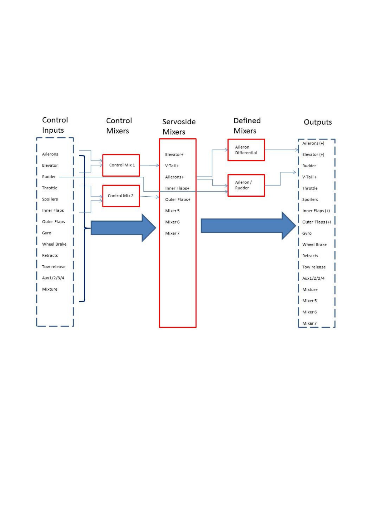
The above schematic simplified representation of the Profi mixer structure, key points to note are
- There are two control mixers which can have two inputs, or a control can be mixed with itself,
the mix percentage can be flight phase specific. These are like the traditional P mixes on other
radios
- The Servo-side mixers are the key to the Profi and replace the normal named mixers on other
radios. These are created by the user, either from scratch or using the provided templates. The
mixer outputs are then assigned to output channels, just like a non-mixed control. The Profi
can use upto 5 mixers per model memory and each mixer can have upto 8 inputs, all
switchable, each input can use either predefined curve or a user created curve. Each mixer can
be used multiple times, i.e. only one mixer required for dual ailerons.
- There are two defined mixers for aileron differential and aileron/rudder, the mix percentages
can be flight phase specific

The Profi includes 2 defined mixers which are non-editable, an aileron differential mixer and
aileron-rudder combi mixer. These are always available and are setup by entering the Mixer
settings menu (GH 2)
The aileron differential mixer is used to set the aileron differential to reduce adverse yaw and/or
fine tuning the roll control on an aerobatic model to give a more axial roll. There are 3 settings for
the differential mix, ON, OFF and SPO LER+, the last option is used when you have ailerons raised
as spoilers (or in crow braking), in this mode the differential is suppressed when the ailerons are
raised so that the down going aileron has full movement for better roll control with the
spoilerons deployed. Note the differential can be set for individual flight phases and differential
can be + ve or –ve, this will depend on the model and the aileron servo set up.
Profi – Mixers
2 -Defined Mixers
The aileron-rudder mix is found under the Combi-Switch tab and this is used to mix some rudder
in when you move the aileron stick, useful for countering adverse yaw and balancing the turns
without having to move the rudder control. As for the aileron differential mixer, the mix %age can
be set for individual flight phases. Also the mix is switchable and a switch for this can be assigned
in the switch assignment tab in the Setup menu (ABC1), the switch can also be used for another
function if you wish, i.e. tow release on a glider so the aileron-rudder mix is off under tow but
becomes active once the tow release is activated. f no switch is assigned the mix is on when a
%age value is added.

The servoside mixers are the key to getting the best out of your Profi and are significantly
different from the control mixers found on most other radios. n the Profi the mixers are created
either from scratch or using the supplied editable templates and then assigned to outputs. Each
mixer can have a total of 8 control inputs and each model memory can have 5 servoside mixers
which can be used multiple times, i.e. you only need one Aileron+ mixer for 2 or 4 separate
aileron surfaces. The first step in using the mixers is to edit one of the presupplied templates or
create your own, this is done in the Define Mixer tab under Setup (ABC1)
Here the mixer list includes supplied templates for Elevator, V-Tail, Ailerons, Flaps nner and
Centre and two blank templates, 7 showing when you scroll down, to change any mixer settings
scroll down to the mixer and enter. Note the above mixer list is the standard mixer templates
loaded for the Glider+ template loading when selecting a new model.
Profi – Mixers
Servoside Mixers
Profi – Mixers
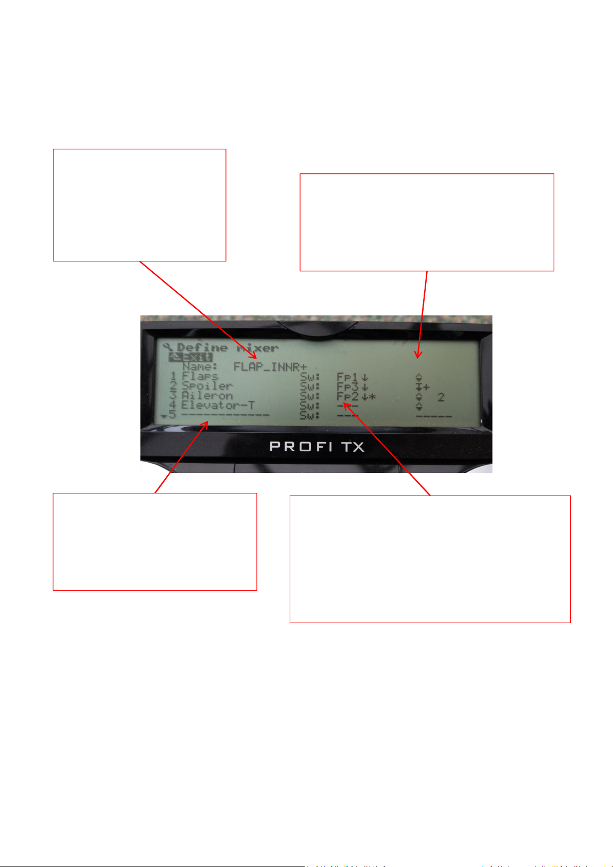
Servoside Mixers
This shows the name of the
mixer, which you can edit, once
a mixer is created it shows up
in the servo assignment tab
(under servo menu JKL4) and
can be assigned to as many
servo channels as you like
The control inputs are listed in the
first column, these can be changed or
new ones added by scrolling down to
the input, pressing enter and then
either operating the control or
scrolling through them.
The 2nd column determines the switch that is used to
activate this mix, this can be selected by either
moving the switch or scrolling through them, note
flight phases and magicswitches can only be selected
by scrolling . Here the flight phases are used as
switches to activate the mixer inputs. f no switch is
selected then the mix is live and values entered in
the mixer menu (GH 3) are always active.
The 3rd column determines the mixer curve for
that input, this can either be one of the
predefined curves as shown by the below
symbols or a user generated curve. These are
selected by scrolling through them and
pressing enter
Profi – Mixers
3 - Servoside Mixers
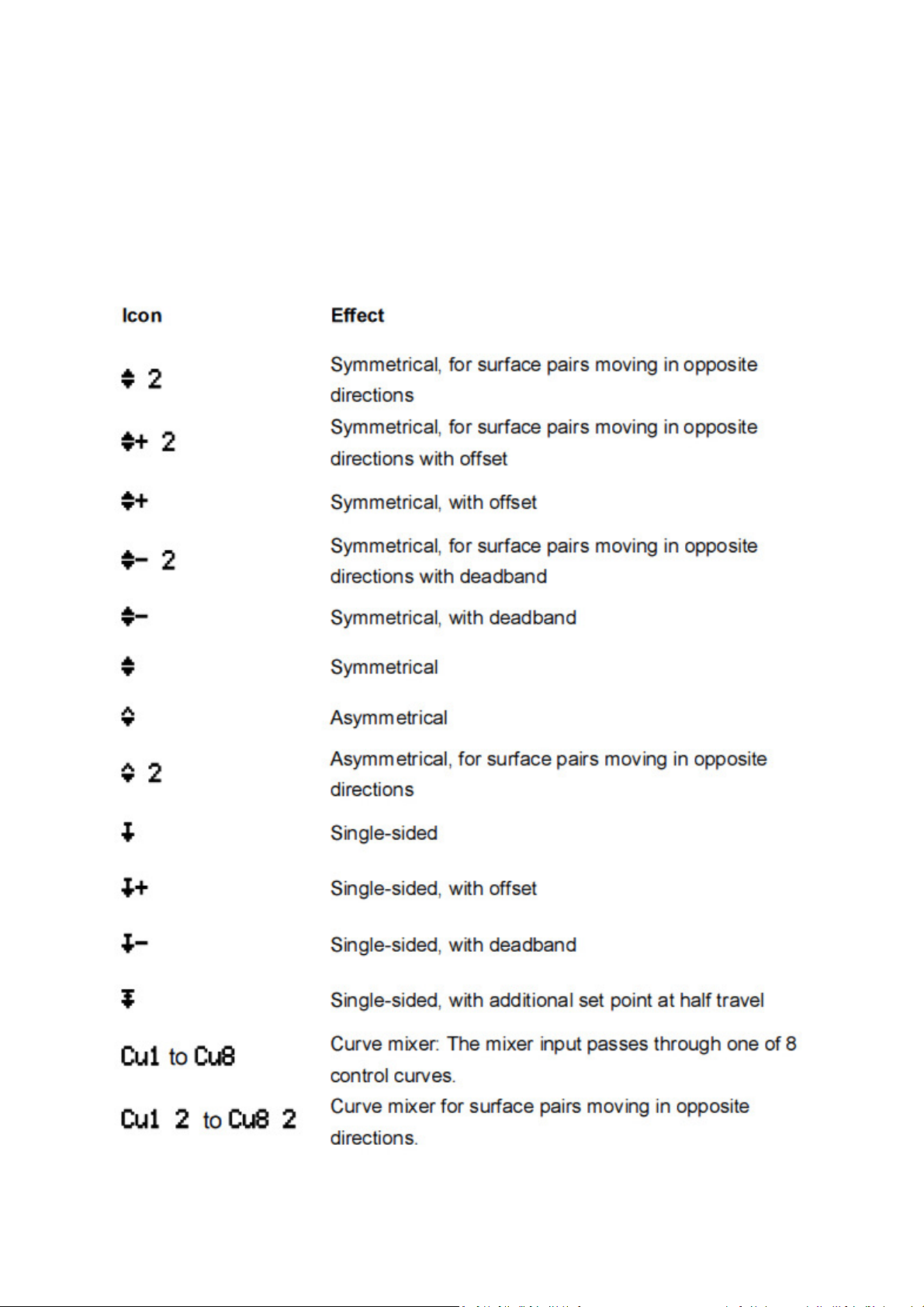
The mixer curves available in the 3rd column are listed below

Profi – Mixers
3 - Servoside Mixers
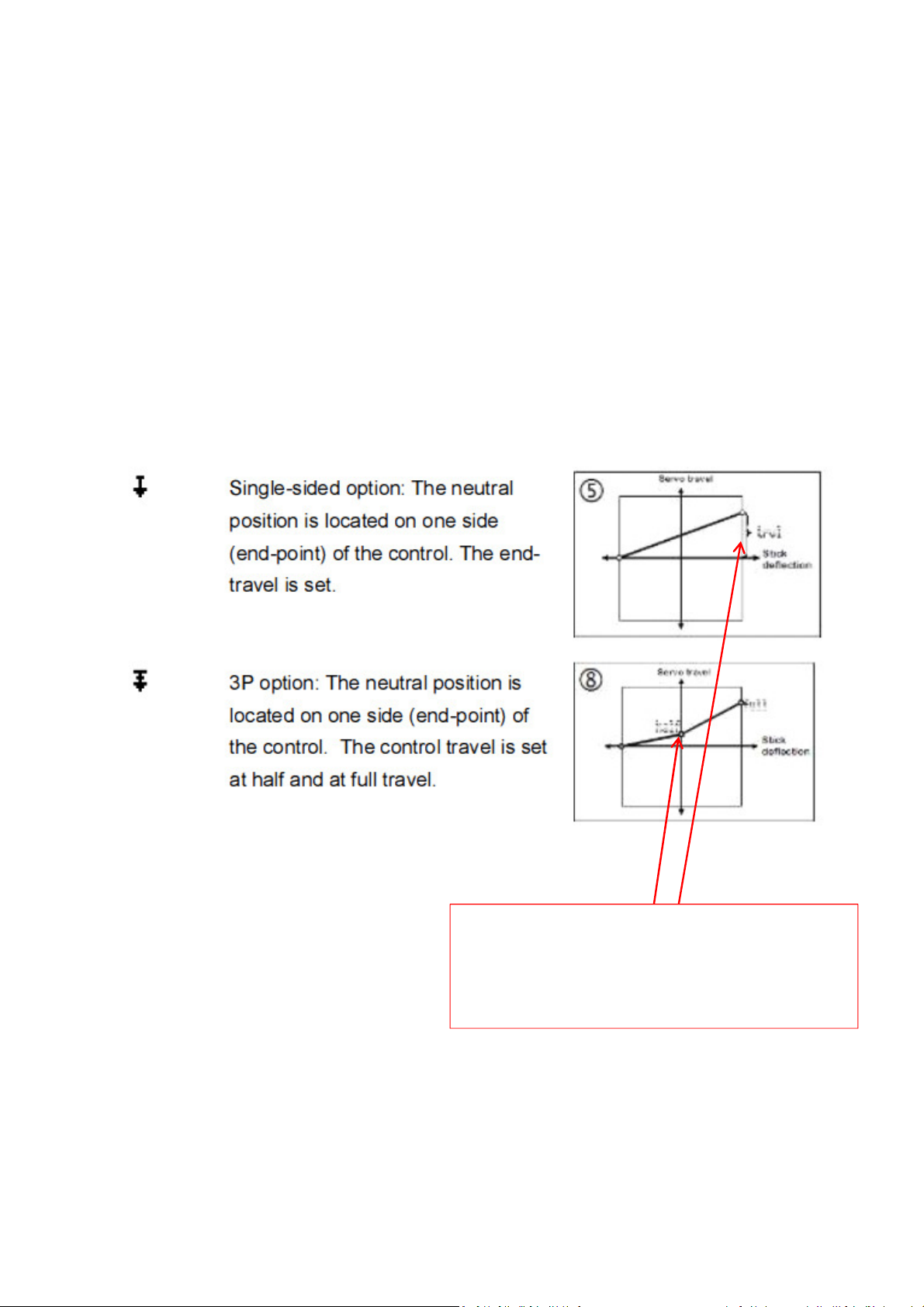
Depending on the type of curve selected the
amount of output from that input is selected in the
mixer setup menu (GH 3)
The standard mixer curves are shown in the manual and referenced
here
Profi – Mixers
3 - Servoside Mixers
Depending on the type of curve selected the
amount of output from that input is selected in the
mixer setup menu (GH 3) , on the standard curves
this will be one or two values depending on the
type of curve used
The standard mixer curves are shown in the manual and referenced
here
Other manuals for Profi TX
2
Other Multiplex Transmitter manuals


Popular Transmitter manuals by other brands


Dejero
Dejero EnGo 3x manual

Rosemount
Rosemount 4600 Reference manual

Speaka Professional
Speaka Professional 2342740 operating instructions

trubomat
trubomat GAB 1000 instruction manual

Teledyne Analytical Instruments
Teledyne Analytical Instruments LXT-380 instructions

Rondish
Rondish UT-11 quick start guide


