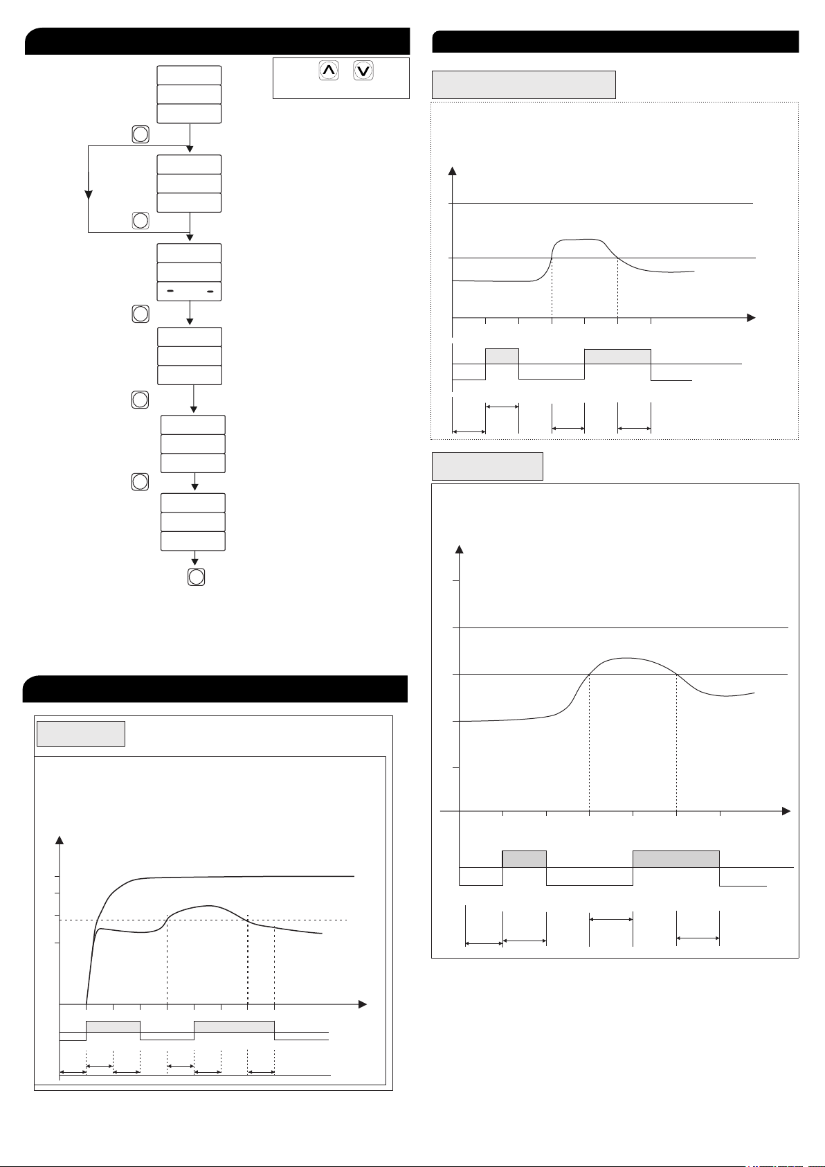
MULTISPAN MPD-192 User manual

Page 1
Auto/Manual/ZVR Reset Function
MPD-192
Motor Protection Device
Over/Under Current
Over/Under Frequency
Over/Under Voltage
Single Phase Prevention
Short Circuit
Unbalance
Phase Loss
Lock Rotor Point
Phase Sequence
Neutral Loss
User Selectable Trip Time
True RMS Measurement
INPUT:
Voltage AC
Direct Voltage AC 30 to 300V(L - N)
50 to 500V(L - L)
Burden
Voltage AC
Current AC
Burden
Current AC
Overload
Frequency
Up to 65A continuous
45.0 to 65.0 Hz
DIMENSION:
Size (mm)
Panel Cutout (mm)
96 (H) X 96 (W) X 52 (D) mm
92 (H) X 92 (W) mm
FEATURES
Protection Available
TECHNICAL SPECIFICATION
TERMINAL CONNECTION
< 0.2VA
< 0.2VA
2.00Amp to 60.0Amp
Supply Voltage 100 to 270V AC, 50Hz
Power Consuption 4VA @ 230 AC MAX
AUXILIARY SUPPLY:
OUTPUT SPECIFICATION:
Relay 2 Nos
Relay Type
st
1 Relay ( NO - C - NC )
nd
2 Relay ( NO - C )
Rating
st
1 Relay 10Amp, 250V AC
nd
2 Relay 5 Amp, 250V AC
For Resistive load
TIME PARAMETER:
Power On Delay 0 to 99 Sec
Initial Time Delay 0 to 99 Sec
Trip Delay Time
0 to 999 Sec
(Voltage, Current, Frequency,
SSP, Unbalance)
Scrolling Time 1 to 99 Sec
Reset Time 0 to 99 Sec
NETWORK SELECTION:
3 Phase - 4 Wire,3 Phase - 3 Wire
DISPLAY AND KEYS:
Display 3 Digit, 3 Line 7 Seg 0.56”,
RED LED
Keys SET, INC, DEC, ACK
TRIP SETTING:
Under Current 0.00 to 60.0 A
0.00 to 60.0 A
Over Current
Under Voltage 50 to 520V For 3Ø - 3W
30 to 300V For 3Ø - 4W
Over Voltage 50 to 550V For 3Ø - 3W
30 to 330V For 3Ø - 4W
Over / Under Frequency 45.0 to 65.0 Hz
Lock Rotor Point 0.5 to 9.0 Scale
Short Circut 1 - 9 Scale
Unbalance 5 - 60%
ENVIRONMENTAL CONDITION:
Working Temperature
Storage Temperature
Relative Humidity
0 to 55°C
0 to 55°C
95 % RH Non-Condensing
IP-65 (Front side As per
IS/IEC 60529 : 2001)
Protection Level
(As Per request)
1 2 3 4 78 9
12
13
14
10
11
5
1617
181920
6
15
S1 S1 S1 S2
S2S2
R
Y
B
Range
Current: 2.00A To 60.0A AC
Voltage (P-P) : 50-500V AC
(P-N) : 30-300V AC
Accuracy Class: 1.0
System:
3Ph-4W/3Ph-3W
NC
CNO
Relay-1
Relay-2
VRVYVBN
100-270V AC
50Hz, 4VA
L N
!
Made in India
www.multispanindia.com
NO
C
100
270V AC
~
50Hz,4VA
CAT III USE CT PROVIDED BY MULTISPAN ONLY
NOTE :
Class 1.0 (Standard)
ACCURACY

Page 2
Key Operation
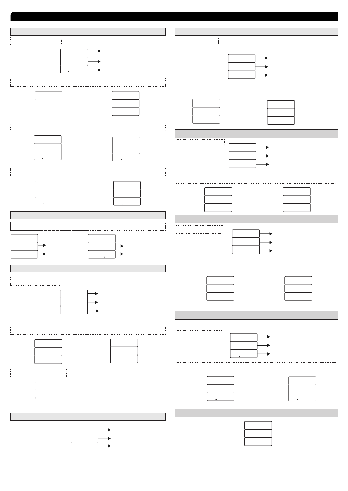
To View Individual Parameters Value OR
Operator Mode
To Reset The Relay Contact manually after
Tripping
Parameter Setting Mode
ACK
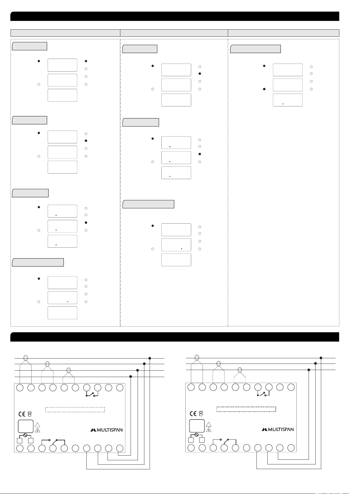
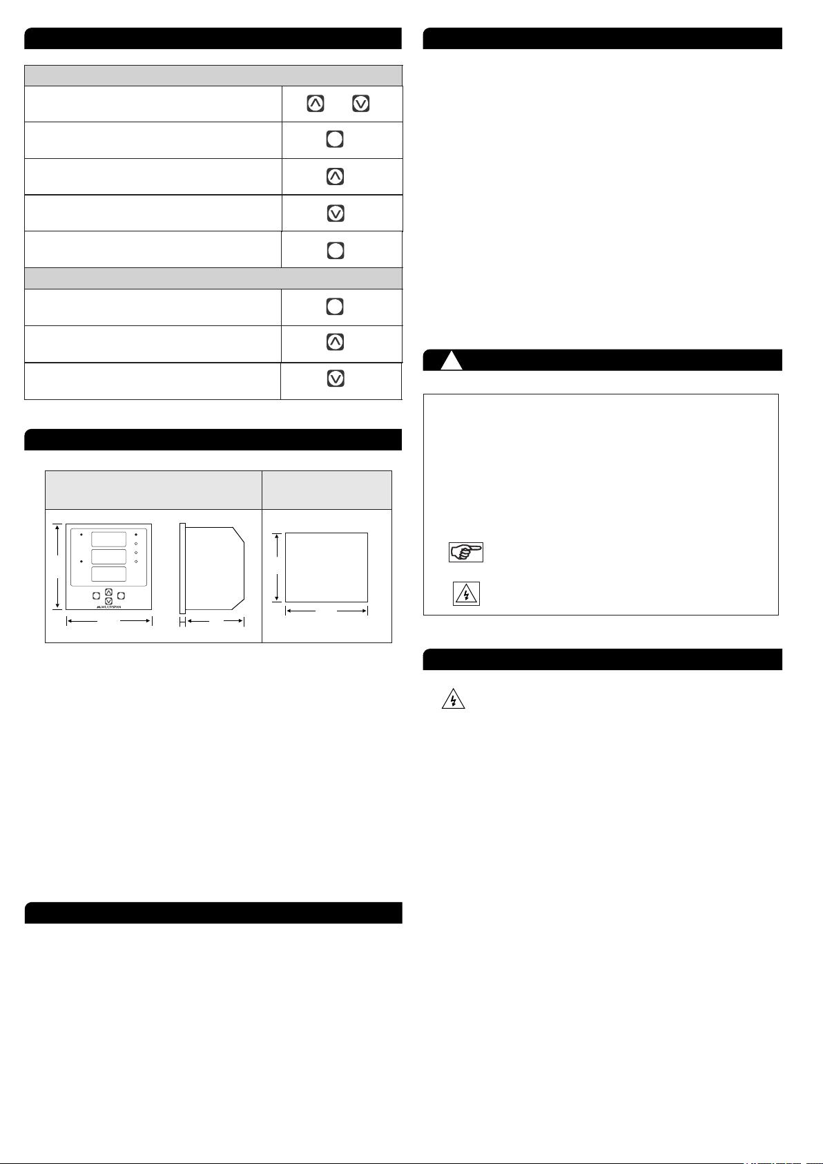
1. Prepare the panel cutout with proper dimensions as shown
above.
2. Fit the unit into the panel with the help of clamp given.
3. The equipment in its installed state must not come in close
proximity to any heating source, caustic vapors, oil steam,
or other unwanted process byproducts.
4. Use the specified size of crimp terminal (M3.5 screws) to
wire the terminal block. Tightening the screws on the
terminal block using the tightening torque of the range of
1.2 N.m.
5. Do not connect anything to unused terminals.
1. This equipment, being built-in-type, normally becomes a
part of main control panel and in such case the terminals
do not remain accessible to the end user after installation
and internal wiring.
INSTALLATION GUIDELINES
2. Do not allow pieces of metal, wire clippings, or fine metallic
fillings from installation to enter the product or else it may
lead to a safety hazard that may in turn endanger life or
cause electrical shock to the operator.
3. Circuit breaker or mains switch must be installed between
power source and supply terminal to facilitate power ‘ON’
or ‘OFF’ function. However this mains switch or circuit
breaker must be installed at convenient place normally
accessible to the operator.
4. Use and store the instrument within the specified ambient
temperature and humidity ranges as mentioned in this
manual.
1. The equipment should be cleaned regularly to avoid
blockage of ventilating parts.
2. Clean the equipment with a clean soft cloth. Do not use
isopropyl alcohol or any other cleaning agent.
3. Fusible resistor must not be replaced by operator.
Read complete instructions prior to installation
and operation of the unit.
WARNING : Risk of electric shock.
All safety related codifications, symbols and instructions
that appear in this operating manual or on the equipment must
be strictly followed to ensure the safety of the operating
personnel as well as the instrument.
If all the equipment is not handled in a manner specified
by the manufacturer, it might impair the protection provided
by the equipment.
WARNING : Risk of electric shock.
1. To prevent the risk of electric shock, power supply to the
equipment must be kept OFF while doing the wiring
arrangement. Do not touch the terminals while power is
being supplied.
2. To reduce electro magnetic interference, use wire with
adequate rating and twists of the same of equal size shall
be made with shortest connection.
3. Cable used for connection to power source, must have a
cross section of 1mm or greater. These wires should have
insulations capacity made of at least 1.5kV.
4. A better anti-noise effect can be expected by using
standard power supply cable for the instrument.
MAINTENANCE
SAFETY PRECAUTION
!
WARNING GUIDELINES
96 52
92
92
3
96
Outline Dimension (mm) Panel Cutout
Dimension (mm)
MECHANICAL INSTALLATION
To Enter In Parameter Setting Mode SET
To View The Voltage Page While Display
Indicate fault
To View The Current Page While Display
Indicate fault
Edited Parameter Value to be Set, And Move
to the Next Step
SET
To Increment Parameter Value
To Decrement Parameter Value
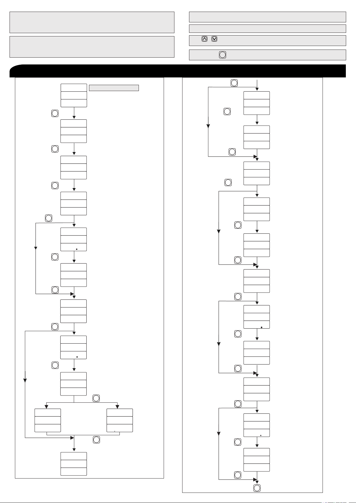
MPD 192
R
Fault
ACK
SET
VLL
L1
L2
L3
VLN
A
KA
240
240
240
MAINTENANCE

Page 3
Under Current fault Message
1) Unc in R Phase
2) Unc in Y Phase 3) Unc in B Phase
4) Unc in RY Phase 5) Unc in YB Phase
6) Unc in RB Phase 7) Unc in RYB Phase
Under Current
R phase Current Value
U N C
R
2 8 7
Fault in R phase
U N C
Y
2 7 2
U N C
B
2 6 3
U N C
R Y
2 7 0
U N C
Y B
2 6 0
U N C
R B
2 5 5
U N C
R Y B
2 5 5
Over Frequency Fault Message
Over frequency
Frequency Value
O V F
5 2 6
Unbalance Fault Message
1) Unb in R Phase
2) Unb in Y Phase 3) Unb in B Phase
4) Unb in RYB Phase
Unbalance
Unbalance Percentage
Between R & B Phase
U N B
R B
5 5
Fault Between R & B Phase
U N B
R y
5 9
U N B
Y B
5 7
U N B
R Y B
5 5
Phase Loss Message
1) R Phase loss
2) Y Phase loss 3) B Phase loss
Phase
Loss
P H A
R
L O S
P H A
Y
L O S
P H A
B
L O S
Phase Sequence Message
Phase
Fault
P H A
S E Q
F L T
Sequence
FAULT MASSAGE
R
Under Frequency Fault Message
Under frequency
Frequency Value
U N F
4 8 6
Single Phase Prevention Fault
S P P
R
1 0 0
R Phase Fault
Single Phase Prevention
R - Phase Voltage Value
2) SPP in Y Phase
S P P
Y
1 0 5
3) SPP in B Phase
S P P
B
1 1 0
R
L O S
S P P
Y
L O S
S P P
B
L O S
S P P
Lock Rotor Point
L R P
R
5 0 0
R Phase Fault
Lock Rotor Point
Phase Current Value
L R P
Y
5 0 0
L R P
B
5 0 0
Frequency Fault Message
SPP Fault Due to Phase Loss
Single Phase Prevention
R Phase
Loss
1) SPP in R Phase
1) SPP in R Phase
2) SPP in Y Phase 3) SPP in B Phase
1) LRP in R Phase
2) LRP in Y Phase 3) LRP in B Phase
Neutral Loss Message
R
1 5 8
S P P
NOTE : Neutral loss Protection available Only,
In Case Of SPP Enable

Page 4
DISPLAY PAGES
1) VLN Page
R
S1 S2
Y
S1 S2
B
S1 S2
R
Y
B
N
WIRING CONNECTION
1) 3 Phase - 4 Wire
R
S1 S2
Y
S1 S2
B
S1 S2
R
Y
B
2) 3 Phase - 3 Wire
2) VLL Page
3) Amp Page
4) Frequency Page
3ø - 4W NETWORK CONNECTION
1) VLL Page
2) Amp Page
3) Frequency Page
1) Fault Massage
R
Fault
L1
L2
L3
VLL
VLN
A
KA
2 4 0
2 4 0
2 4 0
R
Fault
L1
L2
L3
VLL
VLN
A
KA
4 2 0
4 2 0
4 2 0
R
Fault
L1
L2
L3
VLL
VLN
A
KA
5 0 0
5 0 0
5 0 0
R
Fault
L1
L2
L3
VLL
VLN
A
KA
f R Q
5 0 0
H Z
R
Fault
L1
L2
L3
VLL
VLN
A
KA
4 2 0
4 2 0
4 2 0
R
Fault
L1
L2
L3
VLL
VLN
A
KA
5 0 0
5 0 0
5 0 0
R
Fault
L1
L2
L3
VLL
VLN
A
KA
f R Q
5 0 0
H Z
R
Fault
L1
L2
L3
VLL
VLN
A
KA
r
U N C
2 8 7
3ø - 3 W NETWORK CONNECTION 3ø - 3W / 3 - 4W NETWORK CONNECTION
1 2 3 4 78 9
12
13
14
10
11
5
1617
181920
6
15
S1 S1 S1 S2
S2S2
R
Y
B
Range
Current: 2.00A To 60.0A AC
Voltage (P-P) : 50-500V AC
(P-N) : 30-300V AC
Accuracy Class: 1.0
System:
3Ph-4W/3Ph-3W
NC
CNO
Relay-1
Relay-2
VRVYVBN
100-270V AC
50Hz, 4VA
L N
!
Made in India
www.multispanindia.com
NO
C
100
270V AC
~
50Hz,4VA
CAT III USE CT PROVIDED BY MULTISPAN ONLY
NOTE :
USE CT PROVIDED BY MULTISPAN ONLY
NOTE :
USE CT PROVIDED BY MULTISPAN ONLY
NOTE :

Password = 19 » Power On Time & ITD Time Selection
» Under Current, Over Current,
Under Voltage, Over Voltage,
Under Frequency, Over Frequency
Password = 29 » Single Phase Prevention (SPP) Short Circuit, Lock Rotor Point,
Unbalance Current, Phase Sequence,
Phase Loss
Password = 39 » Network Selection
Password = 59 » Display Mode Selection (Hold / Scroll)
Press & Key Together Reset mode , Initial Trigger,Relay Fault
mode selection.
»
Long Press Key
SET
Long Press Key to enter into Password
SET
PARAMETER SETTING
Page 5
Press Key
SET
Enter Password = 19
Power on
Time
(0-99 Sec)
p O N
T I M
5
Initial Delay
Time
(0-99 sec)
Under Current
If Enable
(Enable/Disable)
Under Current
Value
(1.00 to 60.0Amp)
Under Current
Delay Time
(0-999 Sec)
Over Current
(Enable/Disable)
Over Current
Value
(1.00 to 60.0Amp)
Over Current
Trip on
( Time/Curve )
Over Current
Curve Value
(2.5C/5.0C/
10C )
P A S
1 9
Press Key
SET
I T D
T I M
5
Press Key
SET
U N C
E N B
Press Key
SET
U N C
V A L
2 0 0
U N C
T I M
5
O V C
E N B
O V C
V A L
5 0 0
O V C
T R P
T I M
O V C
T I M
5
Over Current
Delay Time
(0-999 Sec)
O V C
C R V
5 0 C
Curve
If
Time
If
Over Voltage
(Enable/Disable)
O V V
E N B
Over Voltage
Value
(50-550V for 3Ø3W)
(30-330V for 3Ø4W)
O V V
4 8 0
v A L
O V V
5
t I M
(0-999 sec)
Over Voltage
Delay Time
U N V
E N B
Under Voltage
(Enable/Disable)
U N V
V A L
3 8 0
Under Voltage
Value
(50-520V for 3Ø3W)
(30-300V for 3Ø4W)
U N V
T I M
5
Under Voltage
Delay Time
(0-999 Sec)
U F
E N B
Under Frequency
Enable / Disable
U F
4 5 0
V A L
U F
5
T I M
Under Frequency
(45.0 to 65.0Hz)
Value
Under Frequency
(0 to 999 sec)
Delay time
O F
E N B
Over Frequency
(Enable / Disable)
O F
5 5 0
V A L
Over Frequency
(45.0 to 65.0Hz)
Value
O f
5
T I M
Over Frequency
(0 to 999 sec)
Value
If
Disable
Press Key
SET
Press Key
SET
If Enable
If Disable
Press Key
SET
Press Key
SET
Press Key
SET
Press Key
SET
If Enable
If
Disable
Press Key
SET
Press Key
SET
Press Key
SET
Press Key
SET
If
Disable
If Enable
Press Key
SET
Press Key
SET
Press Key
SET
Press Key
SET
Press Key
SET
Press Key
SET
Press Key
SET
Press key to Save & exit
Press Key
SET
SET
If
Disable
If
Disable
If Enable
If Enable

PARAMETER SETTING
Page 6
Enter Password = 29
P A S
2 9
Single Phase Prevention
Short Circuit
Short Circuit
Lock Rotor Point
Lock Rotor Point
Scale
Scale
Un Balance
( 1-9 )
( 0.5 - 9.0 )
(Enable / Disable)
(Enable / Disable)
(Enable / Disable)
(Enable / Disable)
S C
S C
L R P
L R P
u n b
S C L
S C L
E N B
2
E N B
2 0
e n b
Un Balance
Percentage
( 5-60% )
u n b
P E R
2 0
Un Balance
Delay Time
( 0-999 Sec )
u n b
t I m
5
Phase
Loss
(Enable / Disable)
p h a
L O s
E N B
S P P
E N B
Phase
Sequence
(Enable / Disable)
p h a
S E Q
E N B
Press Key
SET
Press Key
SET
Press Key
SET
Press Key
SET
Press Key
SET
Press Key
SET
Press Key
SET
Press Key
SET
Press Key
SET
Press Key
SET
If Enable
If
Disable
If Enable
If
Disable
If Enable
If
Disable
Enter Password = 29
P A S
2 9
Enter Password = 59
P A S
5 9
Display Mode
Scrolling
Time
(Hold / Scroll)
( 1-99 Sec )
d I s
m O D
H L D
S C R
T I M
5
Press Key
SET
Press Key
SET
Single Phase Prevention
Trip On
( Voltage/Current )
S P P
T R P
V L T
S P P
T I M
5
Single Phase Prevention
Time
(0 to 999 Sec )
If Enable
If
Disable
Press Key
SET
Press Key
SET
Enter Password = 39
P A S
3 9
Configuration
(3 Wire / 4 Wire )
C O N
3 W
3 P H
3 Phase
Press Key
SET
Press key to Save & exit
SET
Press key to Save & exit
SET
Press key to Save & exit
SET

Page 7
Power On:- 5 Sec
Initial Time Delay:- 5 Sec
SPP:- Enable
SPP Time:- 5 Sec
Fault Reset mode:- Auto
Reset Time:- 5 Sec
Reset Fault:- OFF
5 10 15 20 25 30
100
250
B Phase
Time
Time
R.Y.Phase
OFF
ON
OFF
ON
OFF
Power
ON
Single
Phase
Delay
Reset
Single
Phase
Delay
5 10 15 20 25 30
360
370
380
390
400
B Phase
R,Y Phase
OFF
ON
OFF
ON
OFF
Power
ON
Under
Voltage
Delay Reset
Under
Voltage
Delay
Power On:- 5 Sec
Initial Time Delay:- 5 Sec
Under Voltage:- Enable
Under Voltage time:- 5 Sec
Relay Fault:- OFF
Reset Mode:- Auto
Reset Time:- 5 Sec
Under Voltage:- 380V
Under Voltage
Single Phase Prevention (SPP)
CONTROL FUNCTION
(For Voltage)
0
0
Unbalance
Power On:- 5 Sec
Initial Time Delay:- 5 Sec
Unbalance:- Enable
Unbalance Percentage:- 50%
Unbalance Time:- 5 Sec
Relay Fault:- OFF
Reset Mode:- Auto
Reset Time:- 5 Sec
5 10 15 20 25 30 35 40
3.0A
2.0A
1.0A
B Phase
ITD Reset ITD TRP
Power
ON
Under
Balance
Delay
Under
Balance
Delay
Time
(Second)
R,Y Phase
0
1.5A
OFF
ON
OFF
ON
OFF
Reset
Initial
Reset
Trigger
Time
Manual/Auto/ZVR (Zero Value
Reset)
If Reset
Mode
is Manual
If Reset Mode is Auto/ZVR
( Current ( I ) / Voltage (V) )
( 0-99 Sec )
P A S
2 9
R S T
m O D
M A N
P A S
2 9
r s t
T I M
5
P A S
2 9
I N T
t I g
I
Press Key
SET
Press Key
SET
Press Key
SET
CONTROL FUNCTION
Relay 1
On/Off
P A S
2 9
R L Y
F L T
O N
Relay 2
Power Fault Memory
On/Off
Yes/No
P A S
P A S
2 9
2 9
R L 2
p f m
F L T
O N
y e s
Fault
Fault
Press Key
Press Key
SET
SET
PARAMETER SETTING
Mode
Press key to Save & exit
SET
Together
Press & Key

Specifications are subject to change, since development is a continuous process,
So for more updated operating information and Support,
Please contact our Helpline: 9081078683/9081078681 or
Email at Ver:201101[email protected]
Page 8
Lock Rotor Point
Power On:- 5 Sec
Intial Time Delay:- 5 Sec
Lock Rotor Point:- Enable
Over Current Value:- 2.0A
Relay Fault:- OFF
Reset Mode:- Auto
Reset Time:- 5 Sec
Over Current:- Diseble
Case-1
Lock Rotor Point:- 2.0
5 10 15 20 25 30
2A
4A
5A
B Phase
R,Y Phase
OFF
ON
OFF
Power
ON
ITD TRP
3A
Relay
Time
Lock Rotor Point
5 10 15 20 25 30
2A
4A
5A B Phase
R,Y Phase
OFF
ON
OFF
Power
ON
ITD TRP
3A
Relay
Time
Case-2
Current
TIME
TIME
Current
0
0
Under Current
Power On:- 5 Sec
Initial Time Delay:- 5 Sec
Under Current:- Enable
Under Current:- 3.0A
Under Current time:- 5 Sec
Relay Fault:- OFF
Reset Mode:- Auto
Reset Time:- 5 Sec
5 10 15 20 25 30 35 40
OFF
ON
OFF
ON
OFF
ITD Reset ITD TRP
3.0A
2.0A
1.0A
Y Phase
Power
ON
Under
Current
Delay
Under
Current
Delay
R,B Phase
0
Reset Mode:
1) If Reset Mode Selected is Manual, then the Fault
will Reset Manually by pressing the Reset key on
the instrument.
2) If Reset Mode Selected is Auto, then the Relay will
be reset after Selected Reset time once the healthy
condition achieved.
3) If Reset Mode Selected As ZVR (Zero Value Reset),then
the Relay will be reset after Selected Reset time once
the healthy condition achieved OR Zero Value reached.
Initial Trigger:
1) If Initial trigger mode “I”is selected then Relay will
start working once current is applied.
2) If Initial trigger mode “V“ is selected then Relay will
start working once Voltage is applied.
Relay Fault:
1) If Relay fault selected is “off” than Relay will turn
“off” when fault is achieved, otherwise Relay will
remain turn “on”.
2) If Relay fault selected is “on” then Relay will turn
“on” when fault is achieved, otherwise Relay will
remain turn “off”.
NOTES
Table of contents
Other MULTISPAN Protection Device manuals
Popular Protection Device manuals by other brands

Deister electronic
Deister electronic proxSafe flexx Wiring & installation instructions

GE
GE UR Series C70 instruction manual

Grundfos
Grundfos MP 204 instructions

Southwire
Southwire Surge Guard 34950 troubleshooting guide

Moog
Moog G761K Series Assembly, installation and operation instructions

LEVTECH
LEVTECH LSP-IV2 Series user manual