manuals.online logo
Brands
  1. Home
  2. •
  3. Brands
  4. •
  5. Multitek
  6. •
  7. Intercom System
  8. •
  9. Multitek DIP40 User manual

Multitek DIP40 User manual

1
DIP40 IP INTERCOM DOORPHONE
USER MANUAL
It obeys the rules of AEEE regulations.
Multitek
2
DIP 40 INTERCOM DOORPHONE USER MANUAL
Thank you for choosing access DIP40 intercom doorphone. This user manual was prepared for using the device
more efficiently.
DIP 40 INTERCOM DOORPHONE HAS WARRANTY FOR 2 YEARS AGAINST MANUFACTURING DEFECTS.
Multitek has rights to change the features of the device given in this document prior given any information.
Manufacturer/Importer: Multitek Elektronik San. Ve Tic. A. Ş.
Headquarter / Factory: Meclis Mahallesi Atatürk Cad. No: 47 34785 Sancaktepe / İSTANBUL
Tel: (0216) 420 38 38 Fax: (0216) 415 79 18
E-Mail: [email protected].tr
3
TABLE OF CONTENT
1. SAFETY WARNINGS ..........................................................................................................5
2.TECHNICAL SPECIFICATIONS OF THE DEVICE......................................................................6
2.1. Optional Features......................................................................................................6
2.2. Appearance...............................................................................................................7
2.2.1. Installation on Wall .............................................................................................8
2.2.2. Back Side of DIP40...............................................................................................9
2.2.3. Camera Angle Adjustment.................................................................................10
2.2.4. Network Connection .........................................................................................10
3. USER FEATURES .............................................................................................................11
3.1. Touch Buttons on The Sides of The Screen ...............................................................11
3.2. Using Buttons at Side of The Screen.........................................................................11
3.2.1. Calling “Doorkeeper” or Guard ..........................................................................11
3.2.2. Phonebook Feature...........................................................................................12
3.2.3. To Enter Door Password, Open the Door............................................................13
3.2.4. Remove Door Opening Passwords .....................................................................13
3.2.5. Using Keypad Buttons to Call the Rooms............................................................14
3.2.6. Opening the Door During Ringing or Conversation of a Room with the Door Panel
..................................................................................................................................15
4. DEVICE PROGRAMMING ................................................................................................16
4.1. General Setup..........................................................................................................16
4.1.1. Phonebook Setup..............................................................................................16
4.1.2. Room Setup......................................................................................................18
4.3.1. Block Setup .......................................................................................................23
4.2 Parameters...............................................................................................................27
4.2.2. Languages.........................................................................................................28
4.2.3. Door Release Duration ......................................................................................29
4.2.4. Door Direction...................................................................................................30
4.2.5. Door Password Operations................................................................................30
4.2.6. Setting Date & Time and Camera.......................................................................31
4.3 System Setup............................................................................................................32
4.3.1. System Summary...............................................................................................33
4.3.2. Ip Change (Import Parameters Change)..............................................................33
4.3.3. Diagnostic and System Password Setup .............................................................34
4
5. MANUEL FOR ENTERING THE ROOM PASSWORD TO OPEN THE DOOR............................36
5.1. OPEN THE DOOR RELEASE BY ENTERING THE DOOR PASSWORD...............................36
5.1.1. Setting and Changing Door Password.................................................................36
5.1.2. To Clear All Door Opening Passwords (for apartment manager/technician) ........37
5.2. USİNG PROXIMITY FEATURE TO OPEN THE DOOR.....................................................37
6. DESIGNING PHONEBOOK ON COMPUTER AND TRANSFERRING TO THE DOORPANEL.......38
7. UPDATING DIP40 DOORPANEL SOFTWARE .....................................................................39
8. USING OF DIP40 DOORPANEL.........................................................................................40
8.1. USING DIP40 AS SITE ENTRANCE DOORPANEL..........................................................40
8.1.1. Programming DIP40 Doorpanel as Site Doorpanel..............................................40
8.1.2. Calling Rooms from Site Door Panel...................................................................40
8.2. SETTING DATE AND TIME ON DIP40 .........................................................................40
8.3 MASTER CLOCK FUNCTIONALITY OF BLOCK 1 DOOR 1 ...............................................41
8.4 VOLUME LEVEL SETUP ON THE DOOR PANEL.............................................................41
5
1. SAFETY WARNINGS
For your own and the device safety, you should obey the security warnings;
1. Read the user manual carefully.
2. Read the safety warnings carefully.
3. Remarks about Transport, Shipment and Preservation
During transport and shipment keep the product with its case. The case will protect the product against
the physical damages.
Don’t put heavy weight on to the product or the product case. The product might be damaged.
In case of falling, the product might have permanent damage which will make it non-operational.
Deformation might be caused in case of extreme air conditions such as hot or cold weather. Life time of
the electronic circuits tend to decrease in such conditions.
4. Situations that might be dangerous to human or natural environment:
Beware of the sharp pointed edges of the case
Recycle the product case in the proper recycling bin.
5. Maintenance of the product
The product doesn’t need periodic maintenance. For maintenance and repair please consult to the
authorized services.
By rubbing with dry cloth, you can clean the product periodically.
You can keep the product in its case, when you are not using it.
Before cleaning the product, unplug the connection. Be careful that the cleaning material doesn’t
contain any solvent such as alcohol, gasoline or thinner.
6. Place the product on a plain and stable wall.
7. To prevent any kind of electrical shock, use the product with its original cable.
8. Don’t put any foreign substance in the product. And don’t try to open it with devices that might cause
electrical shock.
9. When maintenance and repair are practiced in places other than the authorized services, the product might
be damaged.
10. Remarks about the energy consumption of the product
The product is designed to work 24/7. Yet to prevent energy consumption, it should be unplugged when
it won’t be used for a long period of time. The user should be aware that each of the terminal stations
that are left on use energy that is not needed.
In case of malfunctioning please consult to an authorized service.
6
2.TECHNICAL SPECIFICATIONS OF THE DEVICE
Screen
4” TFT LCD, Resolution 320x240, LED backlight
Camera
2.0 Mpixel CMOS, adjustable angle, photo cell, night LEDS
CPU
1.5GHz, RAM 1GB, FLASH 4 GB
Input
TF cart, USB, Ethernet
Operating System
Android
Transmission
TCP/IP, SIP protocol
Codec
Voice G.711, video H.264
Network
Ethernet (PoE)
Operating Voltage&Current
12-18VDC (PoE) ,500mA max
Touch Button
16 pieces, programable to seven colors
Door Release
Password, proximity/NFC card
Operating Temperature
-20, +55°c (heating pad for lower temperature)
Humidity
%20-95 non-condensed
Installation
Flash mount or surface mounth with the frame
Color
Black or White
Frame Lights
Photocell, programable to seven colors
Dimensions
141x369x14 mm (172x403x199 mm LED frame)
Protection
IP64, rain, water and dust protected
2.1. Optional Features
Light Frame
Photocell & seven programable colors.
Surface Mount Frame
Photocell & surface mount installation
Rotation Aparatus
Photocell & surface mount installation
Rain Protector
To protect from the rain.
7
2.2. Appearance
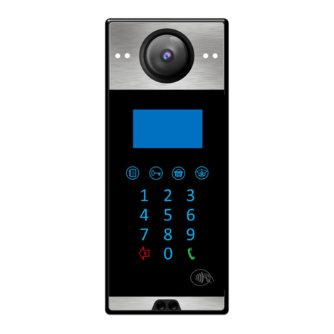
PROXIMITY / MIFARE READER
SPEAKER
CAMERA
NIGHT VISION LEDS
TOUCH FUNCTION BUTTONS
(4 pcs)
4” TFT LCD SCREEN
TOUCH KEY PAD
LIGHT SENSOR
MICROPHONE
Multitek
8
2.2.1. Installation on Wall
Use five screws to mount the wall mount aparatus to the wall.
Use the cable opening to carry out the installation cables.
Use RJ45 cable to connect the device to the network.
Place DIP40 to the wall mount aparatus by using 4 pieces holding tins.
Use 4 pieces 2.9mmx13mm screws given in the giftbox to fix DIP40 and the wall mount aparatus.
WALL MOUNT APARATUS
WAL MOUNT APARATUS
WALL INSTALLATION HOLES
CABLE OPENING
HOLDING TINS
HOLDING TINS
SCREWING
9
2.2.2. Back Side of DIP40
DOOR OPENER
CONTACTS
ETHERNET
CAMERA
ANGLE ADJUSTMENT
LED FRAME
CONNECTION
10
2.2.3. Camera Angle Adjustment
Camera Angle Adjustment:
To change the camera angle, loose the screw shown inside of the RED circle.
Then, the camera becomes loose to change the directions.
When you find the proper position, tight the screw to place the camera.
2.2.4. Network Connection
Connect CAT6 cable coming from PoE switch to Ethernet socket. This cable enables power of the device and
network connection between the network and the device.
Connect door opener device cables to the point where you see the lock icon. These two connection cables lead
to a short circuit when the door release is operated.
11
3. USER FEATURES
3.1. Touch Buttons on The Sides of The Screen
The functions of the buttons are shown on the screen icons. You may activate those functions by touching the
corresponding buttons on the sides of LCD panel. The buttons may be touched in during any screen
appearance.
Waiting Screen: When the panel is in the waiting condition the waiting screen is shown as the following sample
screen picture. The screen shows the name of the apartment, its number and the block number.
01
Main Screen: The main screen shows the function of the buttons. The explanations are put on the side of the
buttons as icons. The device screen shows also the time and the doorpanel environment temperature.
3.2. Using Buttons at Side of The Screen
3.2.1. Calling “Doorkeeper” or Guard
When one of these buttons is touched DOORKEEPER 841 or GUARD with number 99 901 is automatically
called.
During the call operation, one of the following pages is shown according to the status of the call:
If GUARD 99 901 is called:
901
901
901
12
If DOORKEEPER 841 is called:
3.2.2. Phonebook Feature
The phone book is a list of room numbers and their names entered by the phone book program. It is used to
search the names living in the apartment and call the rooms by touching a button. To start using the phone
book feature, please touch the phone book button.
When you touch the PHONEBOOK button, the following screen appears, showing the room numbers and their
inhabitants recorded to the device:
The left side buttons scroll the lines one line up or down. The right-side buttons scroll the lines one page up or
down.
The line selected will be shown in bigger characters. If you touch button ON THE PANEL KEYPAD, the room
shown on the screen will be called. During the calling, you see one of the following screens depending on status
of the call
Example: If the room number 004 and the name HASAN KORUCU;
004 HASAN KORUCU
Please note that the maximum duration of the conversation is 1 minute.
841
841
841
004 HASAN KORUCU
004 HASAN KORUCU
004 HASAN KORUCU
13
3.2.3. To Enter Door Password, Open the Door
Each room in a block may have 4-digit passwords in order to open the main enterence door. (Please see the
section 7 of this manual to enter a room password.)
When the user touches OPEN DOOR WITH PASSWORD button the following screen is shown.
The user enters his 4-digit password. After that one of the following pages is shown.
If the valid password is entered the door release function of the doorpanel works and the door is opened. The
duration of the door release time is programable.
3.2.4. Remove Door Opening Passwords
On the PARAMETERS screen, when the DOOR PASSWORD OPERATİONS button is pressed, the REMOVE DOOR
OPENING PASSWORDS and DELETE ALL DOOR OPENING PASSWORDS screen opens. When you want to activate
or passive door opening passwords, REMOVE DOOR OPENING PASSWORDS is entered and the screen opens as
follows.
ENTER PASSWORD
14
PASSWORD ACTIVE or PASSWORD PASIVE options are selected from the keys to the right of the screen. Pressing
the SAVE key to the left of the screen will perform the desired operation. If you want to cancel the operation,
Press the CANCEL button on the left of the screen.
When the password is active, the following screen opens when the password key is pressed on the login screen.
When the password is passive, the following screen opens when the password key is pressed on the login screen.
3.2.5. Using Keypad Buttons to Call the Rooms
The user calls a room in a block by entering the room number digits by using the keypad of the panel. The only
rooms belonged to the block where the doorpanel is placed may be callable. Therefore, to call a room, the user
enters just the room number without block number. (The block number of the doorpanel is entered by
programming.)
Note: The rooms of the other blocks are not callable via the doorpanel. The door panel may also be able to call
the doorkeepers/guards of the block and the site common numbers as explained belo.
Calling the room numbers:
The room numbers in a block may be addressed as 001, 002, .., 010, …099, 100, ……..799
or 1, 2, .., 9,10,11…99,100,…., 799
To call a room number, the user should enter three digits room number and then should make .
But, the room numbers 1-9 may be also callable as 1-9 or 01-09 or 001-009.
The room numbers 10-99 may be also callable as 10-99 or 010-099. Wrong entered digits are cleared by .
15
Note: Entering (CLR) during dialing, clears the last dialed digit. Entering (CLR) during, ringing or
conversation clears the call, going to the main page (Welcome page).
Example: If the user wants to call the room number 079 or 79, he touches , or and
makes .According to the condition of the called number, one of the following pages is shown.
Example: Calling 079:
Calling the other numbers from the keypad.
It is also possible to call following numbers from the device by using the keypad:
841-849 Doorkeper numbers of the block that the doorpanel DIP40 belongs.
851-859 Block guards’ number of the block that the doorpanel DIP40 belongs.
901-919 site numbers-block 99.
921-959 site numbers-block 99.
3.2.6. Opening the Door During Ringing or Conversation of a Room with the Door Panel
When a room inside of a block is called from the doorpanel the room may open the door by touching the
‘UNLOCK DOOR’ icon on the monitor screen during ringing.
The room monitor (called by the block door panel) may touch UNLOCK DOOR icon to open the door
during conversation.
The block doorkeeper and block guard monitors have also the same feature for opening the door
during ringing/conversation with the door panel.
The room monitor may be connected to the door panels by:
touching OUT DOOR icon on the monitor (The first door panel of the block)
touching THE DOOR ICONS on the intercom menus
dialing XX block number and the door number 801-819.
The user sees the video stream of the door cameras and if touches the UNLOCK DOOR icon the door is
opened.
079
079
079
16
4. DEVICE PROGRAMMING
It is possible to program some parameters of the DIP40 doorpanel by entering to the programming mode of the
device. To enter the programming mode, please touch then dial from the keypad. The
following screen appears.
The page has four icons;
GENERAL SET UP: (Upper left button) to program block/room related parameters. (BLOCK PASSWORD is
needed)
SYSTEM SETUP : (Upper right button) to program system/ device connection parameters. (SYSTEM
PASSWORD is needed.)
HOME : (Lower left button) to return to the Welcome Page.
PARAMETERS : (Lower right button) to programm device related parameters. (BLOCK PASSWORD is
needed.)
4.1. General Setup
When you touch the upper left button to select GENERAL SETUP page, the device asks the password as “ENTER
BLOCK PASSWORD”.
The programmer enters the block password. The default value of the block password is .
After entering the correct password, the following page appears;
The user touches related button to program the parameters of the device.
4.1.1. Phonebook Setup
ENTER BLOCK PASSORD
17
4.1.1.1. Delete Name
To delete the recorded room number from the phone book.
DELETE NAME if the user touches DELETE NAME button the next page becomes with the message “ENTER
ROOM NUMBER AND PRESS OK ‘’
The user enters the room number in three digits. No need to enter the block number because the block
number of the device is entered in some other program. For example, 005 as room number is entered below:
When the three-digit room number is entered the corresponding name appears on the screen. (if there is any).
For example, when 005 is entered, since MULTITEK was entered for the number 005 previously, the screen
shows 005 MULTITEK.
When SAVE is touched the message appears as “ARE YOU SURE?”. If OK is touched the name and number is
erased.
If CANCEL is touched the previous page appears.
ENTER BLOCK NUMBER
ENTER ROOM NUMBER
AND PRESS OK
005
005 MULTITEK
ARE YOU SURE?
ARE YOU SURE?
18
4.1.1.2. Delete Phonebook
To delete all recorded room numbers from the phone book.
DELETE PHONEBOOK: DELETE PHONEBOOK clears all room numbers and names entered. When DELETE
PHONE BOOK is touched the message appears as “ARE YOU SURE?”
If CANCEL is touched the previous page appears.
If OK is touched the name and all numbers are erased and the previous page appears. After erasing the
complete phonebook, the new phonebook may be loaded with SD card or by a computer using Technical
Maintenance Program.
4.1.1.3. Send Phone book
To send other doors in the same block and site door.
4.1.1.4. Back
(To go to the previous page) Icons appears.
4.1.2. Room Setup
ROOM SETUP is used to enter the room number and its name to the phone book feature. Proximity
card allocations to the rooms is also done in this section. If ROOM SETUP icon is touched the above
page appears. ROOM SETUP is used to;
ARE YOU SURE?
ARE YOU SURE?
ARE YOU SURE?
19
4.1.2.1. Edit Name
The phonebook of the device is loaded via SD card and then later those names are editable as explained below.
EDIT NAME is used to edit the name of the room in the PHONEBOOK. If the user touches EDIT NAME button
the following pages appear:
The message “ENTER ROOM NUMBER AND PRESS OK ‘’ appears. The user first enters the room number in
three digits. No need to enter the block number because the block number of the device is entered in some
other program. For example, 005 as room number and is entered.
If the entered number already exists, the existing name appears on the message area. If it is not edited the
message appears as “NOT DEFINED “. If it is blank edited you see a blank line instead of a name.
To edit the name of the room, the user touches the keypad digits consecutivly until the required character
appears on the screen. For example, if charater Z is needed to select, digit 9 should be touched five times.
The maximum number of the characters that may be entered as the room name is 16. The wrong entered
characters are cleared by the button . After entering the name, the user makes . After making ENT,
the new message appears as “TO SAVE TOUCH SAVE BUTTON” The following pages show the sequence of the
operation for the name MULTITEK.
MULTITEK
TO SAVE
TOUCH SAVE BUTTON
ENTER THE NAME
AND PRESS OK
005
MULTITEK
ENTER ROOM NUMBER
AND PRESS OK
20
If the SAVE button is touched the room number and the name is stored.
If CANCEL is touched the pages become the previous page.
4.1.2.2. Add Proximity Card
This feature is used to assign some proximity cards to a room to open the main door by showing the proximity
card to the device. The maximum number of the proximity cards assignable to a room is 5. To assing a
proximity card to a room, the following touches are done and the message appears as “ENTER ROOM NUMBER
AND PRESS OK ‘’;
The user enters the room number of the room whose proximity card will be assigned and makes . The
message shown will be “PLEASE SHOW THE CARD IN 20 SECONDS”. But if the number of the card recorded is
already 5, immediately another message appears as “ALL CARDS RECORDED ALREADY. NO MORE” for 3
seconds and the main screen appears. The following pages are shown for the example room number 007.
TO SAVE
TOUCH SAVE BUTTON
TO SAVE
TOUCH SAVE BUTTON
ENTER ROOM NUMBER
AND PRESS OK
007
PLEASE SHOW THE CARD
IN 20 SEC
007

Other manuals for DIP40

1

Other Multitek Intercom System manuals

Multitek LIP-01 User manual

Multitek

Multitek LIP-01 User manual

Multitek LIP 03 User manual

Multitek

Multitek LIP 03 User manual

Multitek MB-43 User manual

Multitek

Multitek MB-43 User manual

Multitek RL-B43M User manual

Multitek

Multitek RL-B43M User manual

Multitek MB-73 User manual

Multitek

Multitek MB-73 User manual

Multitek MB-40 User manual

Multitek

Multitek MB-40 User manual

Multitek MB-45 Dimensions and installation guide

Multitek

Multitek MB-45 Dimensions and installation guide

Multitek MULTIBUS MB-09 User manual

Multitek

Multitek MULTIBUS MB-09 User manual

Multitek VIP70 User manual

Multitek

Multitek VIP70 User manual

Multitek MB-11 User manual

Multitek

Multitek MB-11 User manual

Multitek MULTIBUS MB-IF User manual

Multitek

Multitek MULTIBUS MB-IF User manual

Multitek MBT-70 User manual

Multitek

Multitek MBT-70 User manual

Multitek MBA-42 User manual

Multitek

Multitek MBA-42 User manual

Multitek MB-12 User manual

Multitek

Multitek MB-12 User manual

Multitek MB-41 MULTIBUS User manual

Multitek

Multitek MB-41 MULTIBUS User manual

Multitek DIP40 User manual

Multitek

Multitek DIP40 User manual

Multitek DIP70 User manual

Multitek

Multitek DIP70 User manual

Multitek MB-74 User manual

Multitek

Multitek MB-74 User manual

Multitek RL-B17M User manual

Multitek

Multitek RL-B17M User manual

Multitek MB-SES User manual

Multitek

Multitek MB-SES User manual

Popular Intercom System manuals by other brands

GRD MAX V2 user manual

GRD

GRD MAX V2 user manual

DEXAPLAN DP 601 - 9-2005 Operation and safety notes

DEXAPLAN

DEXAPLAN DP 601 - 9-2005 Operation and safety notes

Fermax 970114h manual

Fermax

Fermax 970114h manual

Aiphone GH-1KD Installation and operation manual

Aiphone

Aiphone GH-1KD Installation and operation manual

Extel LUKA 12-2014 V2 Installation and user guide

Extel

Extel LUKA 12-2014 V2 Installation and user guide

Emos H4010 manual

Emos

Emos H4010 manual

Cooper Menvier SD3 Installation and operation guide

Cooper Menvier

Cooper Menvier SD3 Installation and operation guide

Elvox Giotto 6344 Installations

Elvox

Elvox Giotto 6344 Installations

Vitek VT-710S product manual

Vitek

Vitek VT-710S product manual

urmet domus micro IP Installation handbook

urmet domus

urmet domus micro IP Installation handbook

Aiphone KC-1SD Installation and operation manual

Aiphone

Aiphone KC-1SD Installation and operation manual

Sysd ST-VD901 instruction manual

Sysd

Sysd ST-VD901 instruction manual

Dynon Avionics SV-INTERCOM-2S Installation and user guide

Dynon Avionics

Dynon Avionics SV-INTERCOM-2S Installation and user guide

Aiphone MK-DGV specification

Aiphone

Aiphone MK-DGV specification

ChinaPST PST-ADO500 user manual

ChinaPST

ChinaPST PST-ADO500 user manual

SVAT VISS7500 user manual

SVAT

SVAT VISS7500 user manual

AYR 758 user manual

AYR

AYR 758 user manual

Ezviz HP7 manual

Ezviz

Ezviz HP7 manual

manuals.online logo
manuals.online logoBrands
  • About & Mission
  • Contact us
  • Privacy Policy
  • Terms and Conditions

Copyright 2025 Manuals.Online. All Rights Reserved.