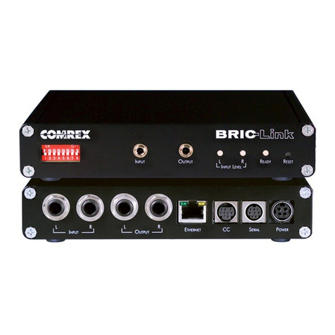
Comrex ACCESS STEREO BRIC IP User manual

...........IntroductIon......................................................................................... 7
.......................About brIc.............................................................................. 8
.......................More About AcceSS rAck......................................................... 9
.......................WhAt coMeS WIth AcceSS rAck ................................................ 9
...........rAck dIAgrAMS And InStAllAtIon .............................................................. 10
.......................reAr PAnel dIAgrAM And deScrIPtIonS.......................................... 10
.......................Front PAnel dIAgrAM And deScrIPtIonS........................................ 11
.......................Mono vS. Stereo........................................................................ 11
.......................PInoutS - AudIo ......................................................................... 11
.......................PInoutS - contAct cloSure ......................................................... 12
.......................PInoutS - SerIAl Port ................................................................. 12
...........SettIng uPAcceSS............................................................................... 13
.......................hookIng uP.............................................................................. 13
.......................About netWork connectIonS ...................................................... 13
.......................SettIng uPAcceSS netWork connectIonS .................................. 13
.......................dynAMIc vS. StAtIc AddreSSIng ..................................................... 15
...........gAInIng AcceSS to AcceSS vIA the conSole connectIon InterFAce.............. 17
.......................toP And bottoM nAvIgAtIon bArS ................................................ 17
.......................netWork tAb............................................................................. 19
...................................ethernet Port Set-uP .................................................... 19
...................................PotS ModeM Set-uP...................................................... 20
.......................Web broWSer ............................................................................ 21
.......................reMoteS tAb.............................................................................. 21
.......................StAtS tAb .................................................................................. 24
.......................AudIo level tAb ........................................................................ 26
.......................conFIgure tAb........................................................................... 26
...........conFIgurIng AcceSS vIA the conSole connectIon InterFAce...................... 27
.......................MAnAge ProFIleS........................................................................ 27
.......................ProFIle SettIngS ........................................................................ 30
.......................SySteM SettIngS ......................................................................... 31
.......................uSer InterFAce........................................................................... 32
.......................cAlIbrAte touchScreen ............................................................... 33
.......................reSet conFIgurAtIon .................................................................. 33
ACCESS StErEo BrIC IP CodEC
tABlE of ContEntS
SectIon 1
SectIon 2
SectIon 3
SectIon 4
SectIon 5
ACCESS Rack 2.8 - FEB 2014
Warning: Advanced Topic
You’ll be seeing me from time to time throughout this manual to
point out ACCESS advanced topics. Feel free to ignore these sections
as the default settings provide good performance for most users.

coMrex corPorAtIon
...........gAInIng AcceSS to AcceSS vIA the Web-bASed InterFAce ............................ 34
.......................AcceSS Web-bASed InterFAce ..................................................... 34
.......................connectIonS tAb........................................................................ 36
.......................StAtIStIcS tAb ............................................................................ 37
.......................AudIo MeterIng tAb................................................................... 38
.......................ProFIleS tAb.............................................................................. 39
...................................buIldIng AProFIle......................................................... 40
...............................................locAl & reMote SettIngS ................................... 41
...............................................brute relIAbIlIty oPtIonS ................................ 41
...............................................PotS SettIngS .................................................. 42
...............................................SettIng uP AcceSS For uSe on PotS Stereo ....... 42
.......................AdvAnced ProFIle oPtIonS .......................................................... 44
...................................AdvAnced chAnnel ......................................................... 44
...................................AdvAnced chAnnel oPtIonS............................................. 45
...................................AdvAnced encoder oPtIonS ............................................ 45
...................................AdvAnced decoder oPtIonS ............................................ 46
.......................SySteM SettIngS tAb ................................................................... 48
...................................contAct cloSureS .......................................................... 50
...................................Aux SerIAl SettIngS........................................................ 50
...................................SecurIty SettIngS ........................................................... 50
...................................brIc norMAl SettIngS ................................................... 51
...................................ModeM SettIngS ............................................................ 51
...................................n/AcIP SIP SettIngS ..................................................... 51
.......................AdvAnced SySteM SettIngS ........................................................... 52
...................................brIc norMAl SettIngS ................................................... 52
...................................ModeM SettIngS ............................................................ 52
...................................StAndArd rtP SettIngS .................................................. 52
...................................n/AcIP SIP SettIngS ..................................................... 52
...................................tcP SettIngS ................................................................ 53
...........MAkIng connectIonS uSIng the Web-bASed InterFAce ................................. 54
.......................creAtIng AreMote connectIon ................................................... 54
.......................dISconnectIng ........................................................................... 56
.......................AdvAnced connectIon oPtIonS .................................................... 56
...................................PASSWord FIlterIng ........................................................ 56
...................................connectIng to ASPecIFIc Port ........................................ 57
...................................bAckIng uP AconnectIon................................................ 59
...................................FAll ForWArd FunctIon .................................................. 60
...................................bAckuP/FAll ForWArd lIMItAtIonS .................................... 60
...........oPerAtIng AcceSS In A24/7 envIronMent............................................... 61
.......................SettIng AcceSS For 24/7 oPerAtIon .......................................... 62
...........PotS (PlAIn old telePhone ServIce) codec connectIonS ......................... 63
.......................PotS codec Set-uP For AcceSS coMPAtIbIlIty ............................ 63
.......................uSIng AcceSS WIth PotS ......................................................... 63
SectIon 6
SectIon 7
SectIon 8
SectIon 9
Warning: Advanced Topic

ACCESS Product Manual
.......................SettIng uP AcceSS For uSe on PotS Stereo................................ 64
.......................rAte droP vS. retrAIn ................................................................ 65
.......................troubleShootIng PotS connectIon ............................................ 66
...........SWItchboArd trAverSAl Server (tS) ......................................................... 67
.......................conFIgurIng SWItchboArd trAverSAl Server .................................. 72
.......................loggIng InAnd SettIng uPthe SWItchboArd trAverSAl Server........ 73
.......................uSIng SWItchboArd tS................................................................ 74
.......................creAtIng uSerS .......................................................................... 76
.......................contAct lIStS ............................................................................ 76
.......................ShAreS ...................................................................................... 77
...........About the AlgorIthMS............................................................................ 79
.......................brIc-hQ1 (hIgh QuAlIty 1)..................................................... 79
.......................brIc-hQ2 (hIgh QuAlIty 2)..................................................... 79
.......................brIc-ulb (ultrA loW bItrAte).................................................. 80
.......................lIneAr PcM .............................................................................. 80
.......................FlAc ....................................................................................... 80
.......................g.711...................................................................................... 80
.......................g.722...................................................................................... 81
.......................AAc......................................................................................... 81
.......................he-AAc .................................................................................. 81
.......................he-AAcv2 .............................................................................. 81
.......................AAc-ld .................................................................................. 81
.......................AAc-eld ................................................................................ 81
...........MultI-StreAMIng .................................................................................... 82
...........IP MultIcASt ......................................................................................... 84
.......................MultIcASt ProFIleS ..................................................................... 84
.......................SettIng uP AMultIcASt reMote .................................................... 85
.......................tIMe-to-lIve .............................................................................. 85
.......................chAngIng Port nuMberS For MultIcASt ........................................ 85
...........StreAMIng Server FunctIon ..................................................................... 86
.......................decodIng AhttP StreAM .......................................................... 86
.......................SIMultAneouSly connectIng AcceSS And StreAMIng ...................... 86
...........gAteWAy oPerAtIon ................................................................................ 87
.......................About gAteWAy oPerAtIon .......................................................... 87
.......................connectIng AS AgAteWAy ............................................................ 87
.......................gAteWAy Mode .......................................................................... 88
...........MAkIng n/AcIP SIP coMPAtIble connectIonS ........................................... 89
.......................More About ebu3326............................................................... 89
.......................ebu3326 In AcceSS................................................................ 89
SectIon 10
SectIon 11
SectIon 12
SectIon 13
SectIon 14
SectIon 15
SectIon 16

coMrex corPorAtIon
.......................n/AcIP SIP ModeS.................................................................... 90
.......................unregIStered Mode ................................................................... 90
.......................regIStered Mode ....................................................................... 90
.......................SIP ServerS ............................................................................... 90
.......................SIP urIS.................................................................................. 90
.......................regISterIng WIth AServer ........................................................... 91
.......................MAkIng SIP regIStered cAllS ...................................................... 92
.......................AdvAnced n/AcIP toPIcS ........................................................... 93
...................................SIP troubleShootIng ..................................................... 94
...................................outgoIng cAll ISSueS ..................................................... 94
...................................IncoMIng cAll ISSueS ...................................................... 94
...................................SolutIonS...................................................................... 95
...................................StunnIng SucceSS ......................................................... 95
...................................FIx oF lASt reSort ......................................................... 95
.......................AdvAnced toPIcS........................................................................ 96
...................................QueStIonS & AnSWerS ..................................................... 96
...................................ebu3326, SIP, Stun And IP coMPAtIbIlIty ..................... 101
...........lIcenSe And WArrAnty dIScloSureS For coMrex AcceSS ............................ 105
...........AcceSS/brIc-lInk trAverSAl Server uSe dISclAIMer .................................. 108
...........conForMIty And regulAtory InForMAtIon ................................................. 109
...........IP coMPAtIbIlIty................................................................................... 113
...........InForMAtIon For It MAnAgerS ................................................................. 115
...........uSIng AcceSS on unIdIrectIonAl netWorkS............................................. 117
...........SPecIFIcAtIonS ........................................................................................
119hQ
...........tAble 1 - xlr PInout............................................................................. 11
...........tAble 2 - AeS3 PInout ........................................................................... 11
...........tAble 3 - contAct cloSure PInoutS.......................................................... 12
...........tAble 4 - SerIAl Port PInoutS ................................................................. 12
...........FIgure 1 - reAr PAnel dIAgrAM And deScrIPtIonS ...................................... 10
...........FIgure 2 - Front PAnel dIAgrAM And deScrIPtIonS .................................... 11
...........FIgure 3 - dIrect connectIon to Internet ................................................ 14
...........FIgure 4 - connectIon to Internet vIA Subnet (or lAn)............................. 14
...........FIgure 5 - toP And bottoM nAvIgAtIon bArS............................................. 18
SectIon 17
SectIon 18
SectIon 19
SectIon 20
APPendIx A
APPendIx b
APPendIx c
APPendIx d
tAble lIStIng
FIgure lIStIng
Warning: Advanced Topic

ACCESS Product Manual
...........FIgure 6 - tcP/IP tAb For ethernet Port conFIgurAtIon .......................... 20
...........FIgure 7 - PotS ModeM conFIgurAtIon tAbS ........................................... 20
...........FIgure 8 - conSole connectIon InterFAce reMoteS tAb .............................. 21
...........FIgure 9 - Add neW reMote Screen ......................................................... 22
...........FIgure 10 - chAnnel StAtS In grAPh ForMAt ............................................. 24
...........FIgure 11 - chAnnel StAtS In nuMerIc ForMAt........................................... 24
...........FIgure 12 - Peer StAtS In grAPh ForMAt .................................................. 25
...........FIgure 13 - Peer StAtS In nuMerIc ForMAt................................................ 25
...........FIgure 14 - AudIo MeterIng ................................................................... 26
...........FIgure 15 - conFIgure tAb Pull doWn Menu ........................................... 27
...........FIgure 16 - AvAIlAble FActory ProFIleS .................................................... 28
...........FIgure 17 - ProFIle SettIngS For AneW ProFIle........................................ 30
...........FIgure 18 - SySteM SettIngS tAb .............................................................. 31
...........FIgure 19 - uSer InterFAce tAb ............................................................... 32
...........FIgure 20 - Web-bASed InterFAce logIn Screen.......................................... 34
...........FIgure 21 - Web-bASed InterFAce Screen................................................... 35
...........FIgure 22 - StAtIStIcS tAb ....................................................................... 37
...........FIgure 23 - AudIo MeterIng tAb ............................................................ 38
...........FIgure 24 - ProFIleS tAb ....................................................................... 39
...........FIgure 25 - creAtIng AneW ProFIle ....................................................... 40
...........FIgure 26a- SySteM SettIngS tAb ............................................................ 48
...........FIgure 26b - SySteM SettIngS tAb ............................................................ 49
...........FIgure 27 - connectIon tAb .................................................................. 54
...........FIgure 28 - Store neW reMote In the connectIonS tAb ............................. 55
...........FIgure 29 - connectIonS PASSWord In the SettIngS tAb.............................. 57
...........FIgure 30 - chAngIng the udP Port For IncoMIng connectIonS................ 58
...........FIgure 31 - bAckuP/FAll ForWArd FunctIonS In the connectIonS tAb .......... 59
...........FIgure 32 - 24/7 oPerAtIon In the connectIonS tAb ................................. 62
...........FIgure 33 - PotS codec vS. PotS Stereo Mode In the ProFIleS tAb ......... 64
...........FIgure 34 - connectIonS tAb durIng An ActIve PotS cAll ........................ 65
...........FIgure 35 - the eFFect oF nAt............................................................... 68
...........FIgure 36 - SWItchboArd tS buddy lISt ................................................... 69
...........FIgure 37 - IncoMIng PAcketS hIttIng nAt router .................................. 70
...........FIgure 38 - “PunchIng Ahole” In AnAt router...................................... 71
...........FIgure 39 - trAverSAl Server SettIngS ...................................................... 72
...........FIgure 40 - enterIng neW unItS.............................................................. 73
...........FIgure 41 - SWItchoArd tS MAIn Account Screen ..................................... 74
...........FIgure 42 - SWItchboArd tS reMote lISt.................................................. 74
...........FIgure 43 - SWItchboArd tS entrIeS on the Web-bASed InterFAce ............... 75
...........FIgure 44 - SWItchboArd uSerS lISt ......................................................... 76
...........FIgure 45 - SWItchboArd contAct lISt ..................................................... 76
...........FIgure 46 - chAngIng ActIve contAct lISt................................................ 77
...........FIgure 47 - ShAre AdevIce ..................................................................... 78
...........FIgure 48 - MultI-StreAMIng ArrAngeMent ............................................... 82
...........FIgure 49 - trAnSMIt on/oFF In the ProFIleS tAb...................................... 83
...........FIgure 50 - MultIcASt SelectIon In the ProFIleS tAb .................................. 85
...........FIgure 51 - gAteWAy connectIon............................................................. 87
...........FIgure 52 - tcP/IP tAb For gAteWAy SetuP.............................................. 88
...........FIgure 53 - n/AcIP SIP SettIngS ............................................................. 91
...........FIgure 54 - SIP StAtuS ........................................................................... 91

coMrex corPorAtIon
About Comrex
Comrex has been building reliable, high quality broadcast equipment
since 1961. Our products are used daily in every part of the world by
networks, stations and program producers.
Every product we manufacture has been carefully designed to function
flawlessly, under the harshest conditions, over many years of use. Each
unit we ship has been individually and thoroughly tested.
Comrex stands behind its products. We promise that if you call us for
technical assistance, you will talk directly with someone who knows about
the equipment and will do everything possible to help you.
You can contact Comrex by phone at 978-784-1776. Our toll free number
in North America is 800-237-1776. Product information along with
engineering notes and user reports are available on our website at www.
Warranty and Disclaimer
All equipment manufactured by Comrex Corporation is warranted by
Comrex against defects in material and workmanship for one year from
the date of original purchase, as verified by the return of the Warranty
Registration Card. During the warranty period, we will repair or, at
our option, replace at no charge a product that proves to be defective,
provided you obtain return authorization from Comrex and return
the product, shipping prepaid, to Comrex Corporation, 19 Pine Road,
Devens, MA 01434 USA. For return authorization, contact Comrex at
978-784-1776 or fax 978-784-1717.
This Warranty does not apply if the product has been damaged by
accident or misuse or as the result of service or modification performed
by anyone other than Comrex Corporation.
With the exception of the warranties set forth above, Comrex Corporation
makes no other warranties, expressed or implied or statutory, including
but not limited to warranties of merchantability and fitness for a
particular purpose, which are hereby expressly disclaimed. In no event
shall Comrex Corporation have any liability for indirect, consequential
or punitive damages resulting from the use of this product.

ACCESS Product Manual
7
Congratulations on purchasing the Comrex ACCESS codec. This product
is the next step in the evolution of audio transportation over networks.
For Comrex, this began in 1976 with the introduction of the Frequency
Extender, followed by ISDN codecs in the early 1990s and POTS codecs in
1996. So we’ve been doing this for a long time.
The ACCESS product is the result of years of our research into the state of
IP networks and audio coding algorithms. This has all been in the quest to
do what we do best, which is to leverage existing, available services to the
benefit of our core customers - radio remote broadcasters.
The heart of this product is called BRIC (Broadcast Reliable Internet
Codec). While others have introduced hardware coined “IP Codecs,” this
is the first product we’re aware of that dares to use the word Internet
“with a capital I.” Given the challenges the public Internet presents, it’s no
small boast to say that this product will perform over the majority of avail-
able connections.
BRIC represents a change that is both desirable and inevitable for remotes.
It’s inevitable because, as available connections move from old fashioned
“circuit switched” style to newer “packet switched” style, technology like
ISDN and POTS codecs will begin to work less and less often. The desir-
ability stems from the new wireless networks that will make remote broad-
casting more mobile, simpler and less expensive. BRIC technology has
been engineered not only to be robust enough for the Internet, but usable
in really challenging Internet environments like 802.11x Wi-Fi, Wi-Max, 3G
cellular and satellite based Internet connections.
Those of us here who have been remote broadcasters have been wishing
for a system like this for a long time. As former broadcasters turned de-
signers, it’s our hope that this kind of enabling technology will tickle the
imagination of the user, enabling more creative and entertaining program-
ming to be broadcast from more diverse and interesting locations. Please
let us know about your unique ideas and adventures by dropping us a
SECtIon 1 IntroduCtIon

Comrex Corporation
8
BRIC (Broadcast Reliable Internet Codec) is a breakthrough technology
with hardware that will deliver audio over the public Internet in much the
same way that ISDN and POTS codecs have performed in the past. BRIC
consists of three pieces:
•RackmountACCESScodec(whichyouareusing)
•PortableACCESScodec
•SwitchboardTraversalServer
We will describe each piece independently:
1) Rackmount ACCESS codec — This product is designed for installa-
tion in a radio station’s “remote rack” and is designed for “always on”
operation. Hence the lack of a power switch. Also, it is envisioned that
this product will be controlled entirely from a computer connected to
the local LAN. There are no user controls on the ACCESS Rack (other
than a recessed reset button) and the only indications are audio meters
and a Ready light to indicate an incoming data stream. After initial con-
figuration, all connection, status and diagnostics are available via the
internal web server and Console Connection Interface.
2) Portable ACCESS codec — This product is engineered to provide the
most convenience for the remote broadcaster on the road. It combines
small size, battery power, clip-on mixer and headphone drivers with an
audio codec capable of remarkable quality on the public Internet.
3) Switchboard Traversal Server — This server exists on the public
Internet at a fixed address and performs several functions. Its use is op-
tional but makes connections between ACCESS codecs much simpler
and removes worries about dynamic IP’s, NATs, and other concerns that
can make peer-to-peer connection over the Internet difficult (especially
over tightly controlled networks like 3G or Wi-Fi). The Switchboard TS
provides the following functions:
a) Communicates with all ACCESS codecs that are provisioned
to work with it. It keeps a log of the IP address of every codec
that wishes to be subscribed.
b) Maintains a “keep alive” channel to each codec subscribed,
allowing Traversal of firewall and Network Address Translators
when receiving an incoming call.
c) Provides each subscribed ACCESS codec with a “Buddy List”
of other users, their current status, and will facilitate connec-
tion to them if desired.
About brIc

ACCESS Product Manual
9
More About AcceSS
rAck
WhAt coMeS WIth
AcceSS rAck
ACCESS Rack incorporates all the features, algorithms and services of
BRIC as defined in the previous sections. Its main function is to provide a
robust, high quality, low-delay audio link in full-duplex over challenging
IP networks like the public Internet. To this end, it provides an intuitive
and attractive Web-based Interface via web-browser and a direct connect
Console Connection Interface. Using these interfaces, you can select op-
erating modes, check audio levels, make and end connections, and check
network statistics of any connections you make. While ACCESS is designed
to handle most network challenges in its default configuration, advanced
options are available to allow customization of parameters that have effect
on link stability and delay.
But wait! There’s more! ACCESS is also a POTS codec. It has a built-in
modem which can be set to make calls over analog phone lines directly to
other units. In this mode, ACCESS can communicate with other ACCESS
devices, or with a range of previous generation POTS codec devices made
by Comrex.
The following items are shipped with a new ACCESS Rack:
(1) ACCESS Stereo BRIC IP Codec (Rackmount)
(1) 6’ Ethernet cable
(1) 6’ Telephone cable
(1) AC Power cord
(1) Operating manual
(1) Warranty card (Please fill out and return)

Comrex Corporation
10
SECtIon 2 rACk dIAgrAmS And InStAllAtIon
Figure 1 - Rear Panel Diagram and Descriptions
This is an IEC connector for the main power. ACCESS works on worldwide
AC power at 110-240VAC 50-60Hz, auto detecting.
This switch determines whether the Line In Left/AES3 In XLR connector is
used for analog or AES3 digital audio input.
Apply balanced analog audio to be sent over the network here. Left chan-
nel is used for mono encoding modes. Level is set to 0dBu (0.775VRMS)
nominal. Full scale input is +20dBu.
Balanced analog audio is available at these ports. Level is set to 0dBu
(0.775VRMS). Full scale output is +20dBu.
A 48KHz AES3 stereo signal is available here. AES3 output is available si-
multaneously with analog. When the AES3 Input is active, the AES3 Output
will lock to the sampling rate and clock signal of the Input.
Asynchronous ancillary data is available here.
Attach a VGA computer monitor here for accessing the Console Connec-
tion Interface.
This button will restart the Rack's computer board.
Attach an analog telephone line here for POTS codec compatibility.
Four sets of contact closure inputs and outputs are available on this port.
These can be used to send signals to the far end of the link or to trigger
remote control gear such as automation equipment.
Attach a PS/2 compatible mouse or keyboard here for use with the console
connection interface.
10/100BaseT Ethernet port for connection to your network.
Available for use with USB keyboards and mice. May also be used with
some 3G USB wireless modems.
1) Ac InPut
2) Analog/AES3 Input
Switch
3) And 4) AnAlog AudIo
InPut
5) And 6) AnAlog AudIo
outPut
7) AeS3 dIgItAl AudIo
outPut
8) SerIAl Port
9) MonItor outPut
10) reSet
11) PotS/PStn
12) contAct cloSureS
13) PS/2 MouSe /
keyboArd Port
14) ethernet Port
15) uSb PortS
1
3 & 4 5 & 6 7 8
11 12 14 15
LINE IN
LEFT/ AES3 IN
LINE IN
RIGHT
LINE OUT
LEFT
LINE OUT
RIGHT
AES3
OUTPUT VGA
SERIAL
USB
MODEM
CONTACT
CLOSURES
RESET
ANALOG
AES3
LAN
2 910
13

ACCESS Product Manual
11
L
R
L
R
S
END
R
ECEIVE
S
TATUS
R
ESET
Figure 2 - Front Panel Diagram and Descriptions
16 17 18
19
16) Send
17) receIve
18) reSet
19) StAtuS
Mono vS. Stereo
PInoutS - AudIo
Peak meter that displays the level of audio being sent locally into the
ACCESS, regardless of whether or not a connection is active. Proper level
is indicated by peaks driving the Yellow LEDs, while avoiding lighting the
Red LEDs (which indicates clipping).
Peak meter that displays the level of audio being sent remotely when a
connection is active. Proper level is indicated by peaks driving the Yellow
LEDs, while avoiding lighting the Red LEDs (which indicates clipping).
Adjustments to this level must be made on the far end of the link.
Recessed button to send ACCESS into hardware reset mode. Approximately
30 seconds are required to reboot when this is pressed.
Indicates several states of Ready:
Off = Network ready, not connected to remote
Red = Network unavailable
Green = Connected to remote
Yellow = Connected to remote but no network (i.e. network connectivity
lost during connection)
Slow Red Blink = Software update in progress
Fast Red Blink = Displaying unit IP address
ACCESS uses its left channel input only for Mono Modes. Right channel
is ignored. Output audio is available at both the left and right outputs in
Mono Mode.
ACCESS audio connections are balanced professional level inputs and
outputs.
Table 1 - XLR Pinout Table 2 - AES3 Pinout
Pin 1 Ground
Pin 2 Audio +
Pin 3 Audio –
Pin 1 Ground
Pin 2 Data +
Pin 3 Data –

Comrex Corporation
12
PInoutS - contAct cloSure
PInoutS - SerIAl Port
Contact closures are available via the male 9-pin D connector on the back
of the ACCESS Rack. Inputs are triggered by shorting the respective input
to Pin 5. Outputs consist of an open collector circuit which, when inac-
tive, will offer a high-impedance path to Pin 5 and, when active, will offer
a low impedance path to Pin 5. These outputs are capable of sinking up to
200mA at a voltage up to 12V. Do not switch AC mains power using these
contacts.
Table 3 - Contact Closure Pinouts
Pin 1 Input #1
Pin 2 Input #2
Pin 3 Input #3
Pin 4 Input #4
Pin 5 Ground
Pin 6 Output #1
Pin 7 Output #2
Pin 8 Output #3
Pin 9 Output #4
The Serial Port is capable of transferring ancillary data to the far end of
the connection. By default, the communication parameters are set for
9600bps, no handshaking, no parity, 8 data bits, one stop bit (9600,n,8,1).
It is pinned on a 9-pin D female in DCE-style pinning. The port is designed
to connect to a 9-pin PC serial port with a straight-through M-F cable.
RS-232 levels are used.
Table 4 - Serial Port Pinouts
Pin # Function Direction
1 CD Unused
2 RX Data From ACCESS
3 TX Data To ACCESS
4 DTR To ACCESS
5 Ground
6 DSR From ACCESS
7RTS To ACCESS
8 CTS From ACCESS
9 RI Unused

ACCESS Product Manual
13
At a minimum, ACCESS will need an audio connection and a network
connection. Levels of all analog audio I/O is 0dBu (0.775V) nominal. This
level will provide 20dB headroom before the clipping point. Input audio is
reflected on the front panel LED based peak meters. Clipping is indicated
by the Red LED on these meters.
ACCESS needs a network connection to be useful. On ACCESS Rack, the
network connection is made via a standard 10/100baseT Ethernet connec-
tion on an RJ-45 connector.
In most ways, ACCESS will look like an ordinary computer to this network.
In fact, ACCESS contains an embedded computer with a Linux-based oper-
ating system and a full network protocol stack.
ACCESS is perfectly capable of working over most LANs, but there may be
situations where a LAN is heavily firewalled, subject to overloaded traffic
conditions, or have security concerns. Better performance is possible if
ACCESS has its own Internet connection. Often, it’s worth the trouble to
install a DSL line especially for ACCESS, especially if the cost is reasonable.
Since there may be bandwidth, firewall, and security concerns with install-
ing ACCESS on a managed LAN, it is recommended that your IT manager
be consulted in these environments. The details that follow assume a work-
ing knowledge of IT topics and network configuration.
We recommend putting ACCESS on a LAN and scoping out its functions
before use. To do this, ACCESS must be given an IP address. This is the In-
ternet location where you can connect to ACCESS through a web browser.
It will also be the address used when another ACCESS is connecting to it.
Every device on an IP network must have a unique IP address. This is a
number between 0 and 4,294,967,295, which is the range of values that
can be represented by 32 binary bits. For simplicity, we break this 32-bit
value into four eight-bit values and represent each as a decimal number
(between 0-255) separated by dots. For example, the Comrex test IP num-
ber is 70.22.155.131.
A device with a public Internet connection can either have a public IP ad-
dress (which is directly accessible by the Internet) or a private IP address,
which is directly accessible only by the LAN on which it is connected.
SECtIon 3 SEttIng uPACCESS
hookIng uP
About netWork
connectIonS
SettIng uP AcceSS
netWork connectIonS

Comrex Corporation
14
Figure 3 shows connection of an ACCESS directly to the Internet using a
public IP address. Figure 4 shows connection to a subnet (or LAN) using
a private IP address, with a gateway router separating the LAN from the
public Internet.
Figure 3 - Direct connection to Internet
Figure 4 - Connection to Internet via subnet (or LAN)
Internet
SERVER X
NAT Router
User A (ACCESS Rack)
User B (laptop)
User C (laptop)
(ex: 192.168.0.37)
(ex: 192.168.0.38)
(ex: 192.168.0.39)
USERs connect to the Internet via
the NAT router’s assigned private
IP addresses.
Server connects to the
Internet via web address
(ex: 70.22.155.133)
NAT router connects to the Internet via a
single public IP address (ex: 208.37.242.6)
and routes this to multiple private IP
addresses, which it assigns to users.
USERs communicate with SERVER X
via the NAT router, which translates
information between public and private
IP addresses.
Internet
Outgoing request made
Response direct to
public IP address
Cable/DSL Modem
ACCESS Rack with public IP address of 70.22.155.131

ACCESS Product Manual
15
To have the ability to make connections normally, without using the
traversal functions of the Switchboard Traversal Server (Switchboard TS),
one of the ACCESS in the link should be connected to a public IP address.
This can be achieved several ways:
1) ACCESS can be the only device connected directly to its Inter-
net link or it can share an Internet link that provides more than
one IP address.
2) ACCESS can be connected behind a NAT router, which can be
programmed to provide public Internet access to it through port
forwarding.
But for now we’ll assume you have a way to set up at least one end of your
ACCESS link with a public IP. In a radio remote environment, this should
probably be the studio end, since you will often have much less control on
the remote side.
ACCESS can be set to its own, fixed IP address (referred to as Static in
Internet-speak) or can obtain its address from the network (known as
Dynamic or DHCP). This concept is entirely independent from the Public
vs. Private concept. Public and private addresses can each be dynamic or
static.
Dynamic (DHCP) — ACCESS is set by default to DHCP addressing, mean-
ing that it looks to your network for assignment of an IP address. If your
network has a DHCP server and this is the way you intend to use it, you
don’t need to alter any settings in the Console Connection Interface. You
will, however, need to know what address is being assigned to ACCESS by
the network. This is easily done by attaching a computer monitor to the
VGA port on ACCESS before applying power. After ACCESS boots, it will
display the current IP address on the monitor. Note: DHCP addresses can
change over time, so you may need to recheck the address if you are hav-
ing trouble connecting.
Finally, there’s one other way to determine the IP address of ACCESS. If
you’re unable to put a computer monitor on the system, you can infer the
IP address by what’s displayed on the front panel LEDs for a few seconds
during the boot process.
DHCP servers typically assign IP address in a standard format. This is
because they must choose addresses that are not in use by the Internet at
large. They will likely choose an address at one of 3 distinct ranges:
192.168.x.x 172.16.x.x 10.x.x.x
dynAMIc vS. StAtIc
AddreSSIng

Comrex Corporation
16
Also, on 192.168 style and 172.16 style subnets, the third entry will typi-
cally be a single digit (often 0 or 1). You can usually find out the DHCP
assignment style by querying a Windows computer on the same LAN using
Run->Cmd->ipconfig. If you know your DHCP server assigns addresses us-
ing one of the first two formats (or you know the DHCP assignment range
on a 10.x.x.x network) you can usually derive the true IP address by the
front panel LEDs. They will display a “coded” version of the IP address as-
signed for a few seconds during boot just before the ACCESS enters opera-
tional mode. During this time, the Ready light on the front panel flashes
quickly, and the Level LEDs display the last 4 digits of the IP address. This
is best shown by example:
Assume you are using a Linksys router on your network that has a built-
in DHCP server. You may be aware that by default this router assigns IP
addresses using the range 192.168.1.2-255. Let’s assume that when con-
nected, the ACCESS is assigned an IP address of 192.168.1.7. The LEDs will
display the last four decimals of this address (including zeros) so during
boot you will see the following code:
L Send will display 1 LED
R Send will display 0 LEDs
L Receive will display 0 LEDs
R Receive will display 7 LEDs
You can now assume that your ACCESS has the address of 192.168.1.007
Static IP — Setting a Static IP requires that you enter some details into the
ACCESS. You will need to enter the following information via the Console
Connection Interface:
•IP address of the ACCESS – make sure this has been provided
by your ISP or that nobody else on your LAN is using this address.
•Subnet Mask – A series of numbers that indicate the range of
your LAN addresses. If in doubt, try 255.255.255.0.
•Gateway Address – The address of the Internet gateway on your
account. If in doubt, try the first three number of your IP address
with the last digit of 1 (e.g. xxx.xxx.xxx.1).
More details on how to input this information are contained in the next
section.

ACCESS Product Manual
17
toP And bottoM
nAvIgAtIon bArS
SECtIon 4 gAInIng ACCESS to ACCESS vIA thE ConSolE ConnECtIon IntErfACE
The use of the Console Connection Interface is required when configuring
the IP parameters. It also provides access to many of the features found
in the Web-based Interface. We’ll cover the Console Connection Interface
here, and the Web-based Interface in later sections.
Using the Console Connection Interface requires that you attach a PS/2 or
USB style keyboard and video monitor to the appropriate jacks on the rear
panel of ACCESS Rack. You may also attach an USB or PS/2 style mouse
to make navigation easier. When using the PS/2 style keyboard or mouse
remove and re-apply power after connection.
As shown in Figure 5, all menus on the Console Connection Interface
contain the top and bottom navigation bars, which contain shortcuts to
various setup and status displays. The top bar contains four tabs:
•Network – Enable and disable the Ethernet Port or POTS Modem.
Configure IP parameters.
•Remotes – Create and configure the addresses and profiles of the
various outgoing connections. Essentially, this creates an editable
“phone book” of places you connect to.
•Stats – View network performance data of active connections
•Configure – Create profiles for outgoing connections, manage
how incoming connections are treated, and change configurations
of additional features like audio switching, contact closures and
incoming password security.

Comrex Corporation
18
The bottom bar contains the following shortcuts:
•Pickboard – Allows use of the pop-up keyboard for text entry and
eliminates the use of a PS/2 or USB style keyboard.
•Chat – Jumps immediately to the chat screen/pickboard, allowing
text messaging to other ACCESS users.
•F1/Arrow/Enter – As shown in the legend on the bottom of the
page, the F1 key on the keyboard provides access to the pull-down
menus and the Arrow and Enter keys are used to navigate.
Top
Bottom
Figure 5 - Top and Bottom Navigation Bars

ACCESS Product Manual
19
The Network Tab is shown in Figure 5. The Ethernet port and POTS
modem may be individually enabled and configured via this interface.
The main tab of interest in configuring the Ethernet port is shown in
Figure 6, the TCP/IP Tab. Use the drop down menu to select one of the
four configuration options for Ethernet - Static, DHCP, PPPoE, Gateway.
For DHCP (Dynamic) connections, simply select DHCP and the unit will
automatically obtain the network settings.
If your connection requires a static, or fixed IP address, you can enter that
along with your subnet mask and gateway information in the appropriate
fields. If you know the address of your DNS server, enter it here. This is
required for use of Switchboard TS and the internal browser functions.
PPoE (Point-to-Point Protocol over Ethernet) is used by some DSL and
WiMAX services to establish and end sessions much like a dial-up modem
does. Most IP connections don’t use it and it can usually be ignored.
If your ISP requires PPoE session to be established, rather than entering
IP information you may enter a user name and password to establish
connection. These are supplied by your ISP.
PPoE connections always use dynamic IP addressing. When using PPoE an
IP address will be assigned by the DHCP server at the ISP and will appear
on the bottom bar of the network menu.
The Gateway option is an advanced topic and is described in the gAteWAy
oPerAtIon section. It should not be enabled for most applications.
After the Ethernet parameters are set, you may enable the Ethernet port.
For DHCP connections, this will prompt ACCESS to acquire an IP address
from the DHCP server. Enabling and disabling the Ethernet port is
equivalent to “releasing” and “renewing” IP addresses. The acquired IP
address will appear on the bottom bar of this display.
netWork tAb
netWork tAb - ethernet
Port Set-uP

Comrex Corporation
20
The modem in the ACCESS can be configured for either Non-PPP Mode or
PPP Mode, as shown in Figure 7. Most users may leave the default settings.
Non-PPP (POTS Codec) Mode is the default setting. This is used to place
a call to another codec directly over the telephone line with no Internet
Service Provider involved. This is the only mode available to connect to
other Comrex POTS codecs. Because of the narrow bandwidth of dial-up
Internet connections, use of POTS Codec Mode is strongly preferred over
modem PPP Mode. No options are available for Non-PPP Mode. The extra
modem init string for this mode is done in the System Settings Tab (the
Advanced box must be selected in order for this option to appear).
PPP Mode allows the use of a dial-up Internet Service Provider. Configure
your ACCESS with your ISP information. The ACCESS will function like an
IP codec over the link, connecting to other ACCESS IP addresses.
PPP Mode should only be used when connecting to an Internet Service
Provider via the modem. In this mode, you will need to enter the phone
number, user name and password settings provided by your ISP.
Once your ISP parameters are configured, you may enable the modem and
the call to your ISP will be dialed automatically. This call will be maintained
until the modem is disabled in the Network Tab.
netWork tAb - PotS
ModeM Set-uP
Figure 7 - POTS Modem Conguration Tabs
Figure 6 - TCP/IP Tab for Ethernet Port Conguration
Table of contents
Other Comrex Conference System manuals

Comrex
Comrex Access NX User manual

Comrex
Comrex Bluebox User manual

Comrex
Comrex BRIC-Link User manual

Comrex
Comrex LiveShot Portable User manual

Comrex
Comrex ACCESS MultiRack User manual

Comrex
Comrex LiveShot Portable User manual

Comrex
Comrex KKFI User manual

Comrex
Comrex ACCESS Rackmount Installation guide

Comrex
Comrex BRIC-Link User manual