1Operating 5C : -55℃to 125℃Reference Temperature : 25℃
2Rated Voltage See the previous pages. The rated voltage is defined as the maximum voltage which may
be applied continuously to the capacitor.
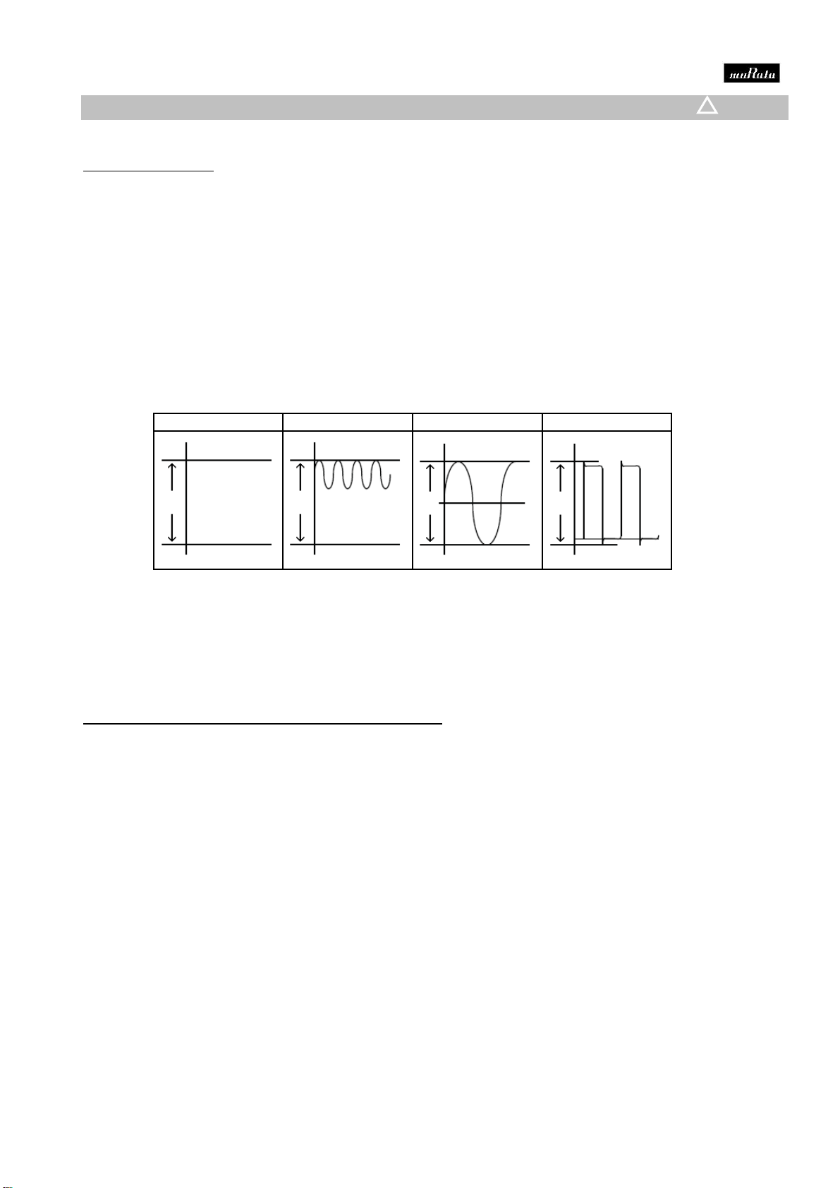
When AC voltage is superimposed on DC voltage, VP-P or VO-P,
whichever is larger, should be maintained within the rated voltage
3Appearance No defects or abnormalities. Visual inspection.
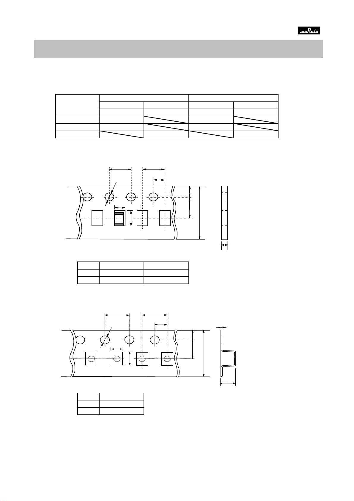
4Dimension Within the specified dimensions. Using calipers.
5Dielectric Strength No defects or abnormalities. No failure should be observed when 250% of the rated voltage
is applied between the terminations for 1 to 5 seconds,
provided the charge/discharge current is less than 50mA.
6Insulation More than 10,000MΩ The insulation resistance should be measured with a DC voltage
Resistance not exceeding the rated voltage at 25℃and 75%RH max.
and within 2 minutes of charging, provided the charge/discharge
current is less than 50mA.
7Capacitance Within the specified tolerance. The capacitance/Q should be measured at 25℃at the frequency
and voltage shown in the table.
C:NominalCapacitance (pF)
9Capacitance Temperature Within the specified tolerance.(Table A-1) The capacitance change sholud be measured after 5 min. at
Coefficent each specified temp. stage.
The temperature coefficient is determind using the capacitance
measured in step 3 as a reference.
When cycling the temperature sequentially from step 1 through 5
the capacitance should be within the specified tolerance for the
Capacitance Within ±0.2% or ±0.05pF temperature coefficient and capacitance change as Table A-1.
Drift (Whichever is larger.) The capacitance drift is caluculated by dividing the differences
betweeen the maximum and minimum measured values in the
step 1,3 and 5 by the cap. value in step 3.
10 Adhesive Strength of No removal of the terminations or other defect Solder the capacitor on the test jig (glass epoxy board) shown
Termination should occur. in Fig.3 using an eutectic solder.
Then apply 10N force in parallel with the test jig for 10±1seconds.
The soldering should be done either with an iron or using the
reflow method and should be conducted with care so that the
soldering is uniform and free of defects such as heat shock.
11 Vibration Appearance No defects or abnormalities. Solder the capacitor on the test jig (glass epoxy board) in the
Resistance same manner and under the same conditions as (10).
Capacitance Within the specified tolerance. The capacitor should be subjected to a simple harmonic motion
having a total amplitude of 1.5mm, the frequency being varied
Q30pFmin. : Q≧1400 uniformly between the approximate limits of 10 and 55Hz.
30pFmax.: Q≧800+20C The frequency range, from 10 to 55Hz and return to 10Hz,
should be traversed in approximately 1 minute.
C:NominalCapacitance (pF) This motion should be applied for a period of 2 hours in each 3
mutually perpendicular directions(total of 6 hours).
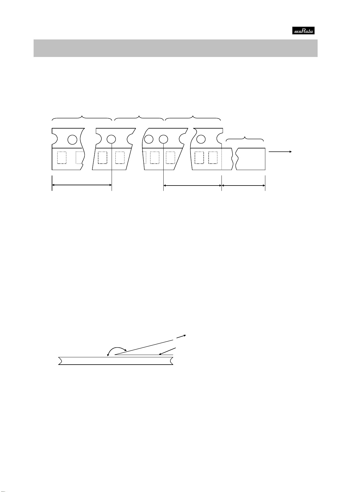
12 Deflection Appearance No defects or abnormalities. Solder the capacitor on the test jig (glass epoxy board) shown
in Fig.1 using an eutectic solder.
Capacitance Within ±5%or ±0.5pF Then apply a force in the direction shown in Fig 2 for 5±1seconds.
Change (Whichever is larger) The soldering should be done by the reflow method and should
be conducted with care so that the soldering is uniform and
free of defects such as heat shock.
13 Solderability 75% of the terminations is to be soldered Immerse the capacitor in a solution of ethanol (JIS-K-8101)
of Termination evenly and continuously. and rosin (JIS-K-5902) (25% rosin in weight propotion).
Preheat at 80 to 120℃for 10 to 30 seconds.
After preheating, immerse in an eutectic solder solution for
2±0.5 seconds at 230±5℃or Sn-3.0Ag-0.5Cu solder solution
for 2±0.5 seconds at 245±5℃
■SPECIFICATIONS AND TEST METHODS