VJ-1608 Hybrid INSTALLATION MANUAL
7 VJ1608HYE-I-00
1
2
1
2
1
1
12 3 4 5
12 3 4 5
1
3 5
2 43 5
2 4
12 3 4
2 3 4
7 Following the same procedure as in step 6, insert
the ink packs (M, Y: 2 each) into the ink pack
slots (M, Y: 2 locations each) on the right side of
the rear of the printer.
Ink packs are specified depending on the colors of
the ink pack.
Match the mark on each slot with the color of the
ink pack.
"Ink Refill **%" is displayed on the operation
panel and ink replenishment starts.
The ink replenishment takes about 12 minutes.
Ink filling operation and pause operation are
repeated during the ink replenishment.
When "100%" is displayed, the ink replenishment
is complete.
Do not perform the following operations during
ink filling.
Do not turn the printer OFF.
Do not unplug the power cable.
Do not open the front cover.
Do not raise the media loading lever.
After the ink replenishment is complete, "SubTank
Refill **%" is displayed on the operation panel
and Subtank Refill starts.
When "100%" is displayed, the Subtank refill is
complete.
After the Subtank refill is complete, "Media End"
is displayed on the operation panel.
If the Nozzle check printing is performed immedi-
ately after the ink replenishment is complete, the
following results may occur.
Printed line becomes blurred.
Printing partially.
In such cases, follow the Operation Manual "6.2.3
Head cleaning" and charge a small amount of ink.
Then, check the printing result.
If there is no improvement in the print result even
after refilling a small amount of ink, leave the
printer for one hour or more, and refill a small
amount of ink again.
If there is still no improvement, contact MUTOH
local dealer.
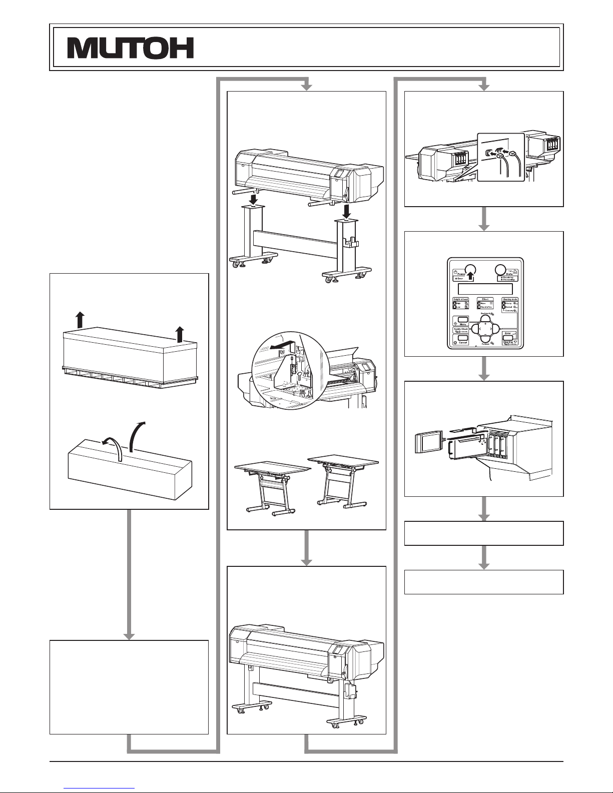
7 Installing the ink packs
This section explains how to install ink packs.
Follow the steps below to install ink packs.
1.Turn ON the product.
The product starts initial operation.
After the initial operation is complete, "Start Ink
Charge -> E" is displayed on the operation panel.
2.Press the [Enter] key on the operation panel.
"During Washing" is displayed on the operation
panel and the printer starts discharging the ship-
ment fluid.
After discharging shipment fluid is complete,
"Wash retry? No" is displayed on the operation
panel.
When cleaning the print head again before ink fill-
ing, select "Yes" to press [+] key or [-] key on the
operation panel. Then press [Enter] key and clean
the print head.
3.Press the [Enter] key on the operation panel.
"Insert InkCartridges" is displayed on the opera-
tion panel.
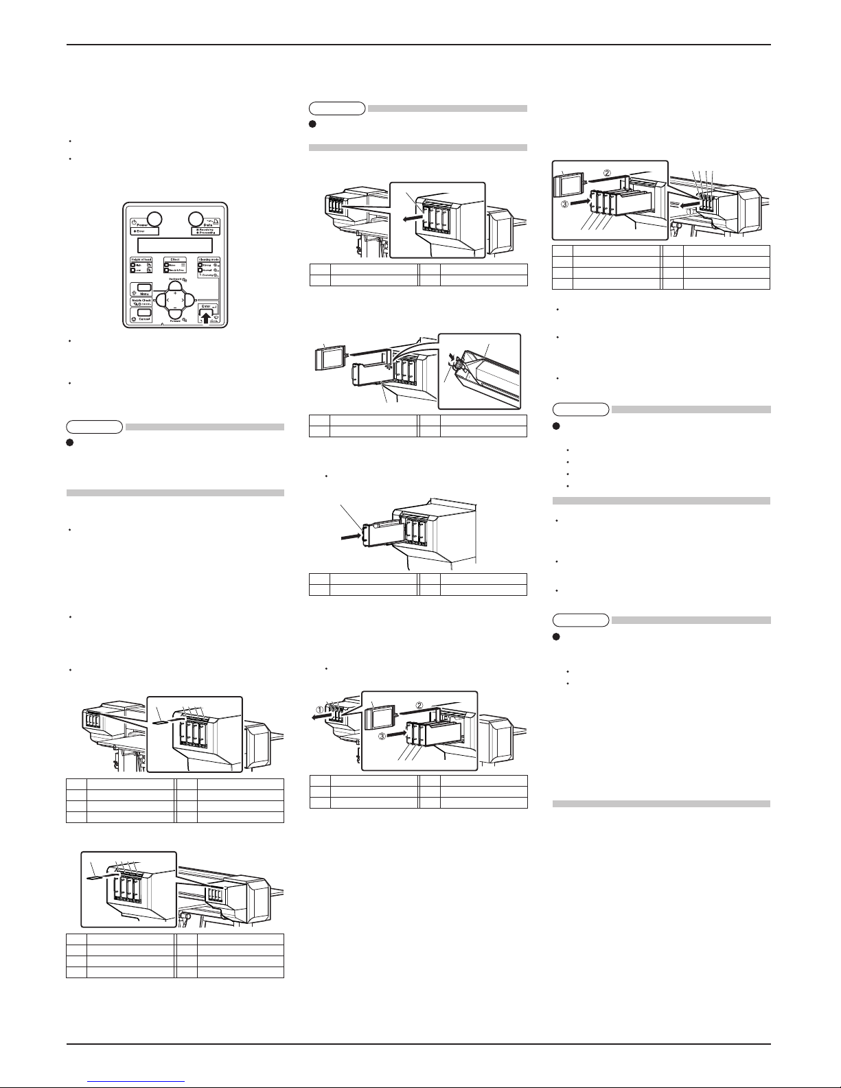
4.Remove the ink S/C cards and ink packs (8 each)
from the bag.
5.Insert the ink S/C cards (8 count) one-by-one into
the S/C card slots (8 locations).
Ink S/C cards are specified depending on the col-
ors of the ink pack.
Match the mark on each slot with the color of the
ink pack.
Insert the S/C card all the way to the end of the slot.
a.Left-rear side of the printer
b.Right-rear side of the printer
6.Insert the ink packs (K, C: 2 each) one-by-one into
the ink pack slots (K, C: 2 locations each) on the
left side of the rear of the printer.
The Steps a to c for installing ink pack K (slot K1)
is described below.
a.Pull out ink pack slot K1.
b.Shake the ink pack K two to three times gently
before inserting it into ink pack slot K1.
c.Re-insert ink pack slot K1.
Insert the ink pack slot all the way to the end of
the slot.
d.Following the same procedure as in steps a to c,
install the remaining ink packs (K: 1 pack, C: 2
packs) into the ink pack slots.
Ink packs are specified depending on the colors
of the ink pack.
No. Name
1 Ink S/C card
2 S/C card slot K1
3 S/C card slot K2
No. Name
4 S/C card slot C1
5 S/C card slot C2
No. Name
1 Ink S/C card
2 S/C card slot M1
3 S/C card slot M2
No. Name
4 S/C card slot Y1
5 S/C card slot Y2
No. Name
1 Ink S/C card
2 Ink pack slot M1
3 Ink pack slot M2
No. Name
4 Ink pack slot Y1
5 Ink pack slot Y2
No. Name
1 Ink pack slot K1
No. Name
1 Ink pack K
No. Name
2 Ink pack slot K1
No. Name
1 Ink pack slot K1
No. Name
1 Ink pack
2 Ink pack slot K2
No. Name
3 Ink pack slot C1
4 Ink pack slot C2
NOTE
NOTE
NOTE
NOTE