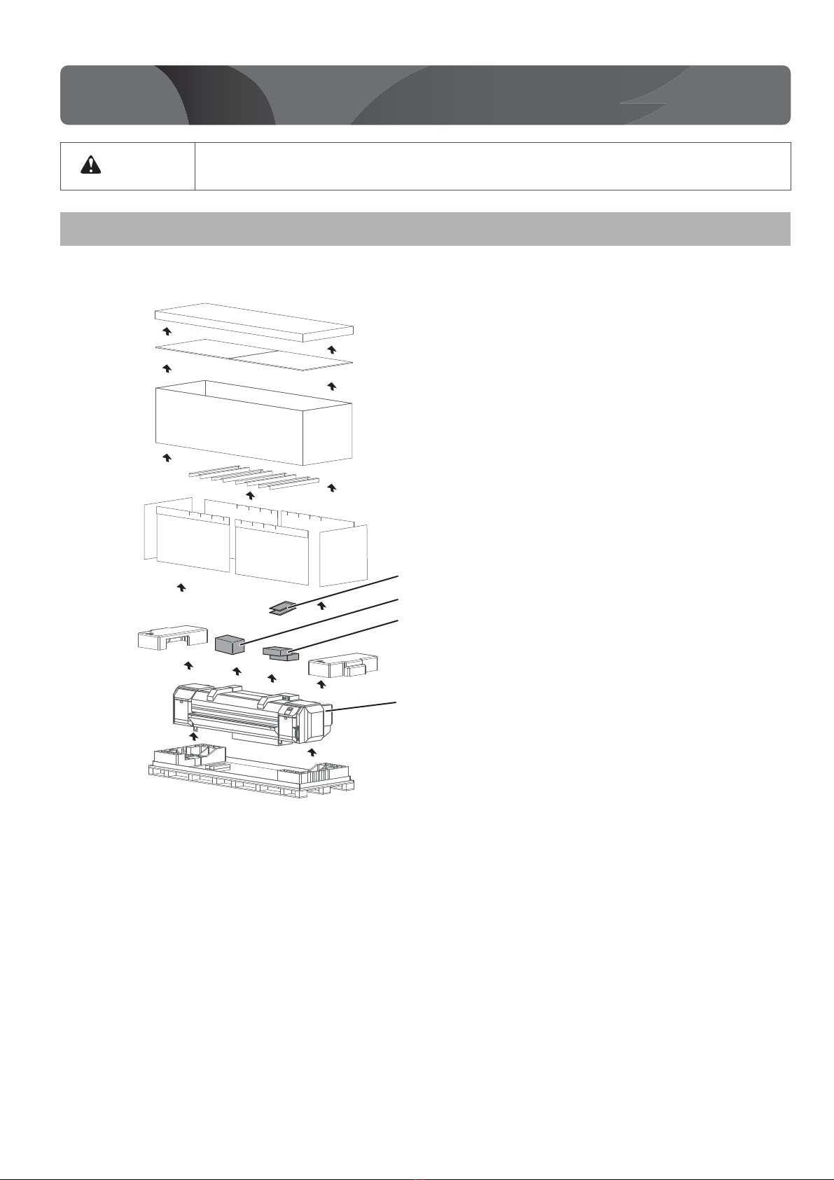
Muton ValueJet VJ-1627MH User guide

Unpacking . . . . . . . . . . . . . . . . . . . . . . . . . . . . . . . . . . . . 2
Assembling . . . . . . . . . . . . . . . . . . . . . . . . . . . . . . . . . . . 8
Connecting the cables . . . . . . . . . . . . . . . . . . . . . . . . 20
Setup . . . . . . . . . . . . . . . . . . . . . . . . . . . . . . . . . . . . . . . . 22
Test printing . . . . . . . . . . . . . . . . . . . . . . . . . . . . . . . . . 33
Sleep Mode . . . . . . . . . . . . . . . . . . . . . . . . . . . . . . . . . . 45
Accessing the Manuals . . . . . . . . . . . . . . . . . . . . . . . . 47
Safety Instructions. . . . . . . . . . . . . . . . . . . . . . . . . . . . 48
• Unauthorized copying or duplication of the whole or part of the contents of this Guide is prohibited.
• Every care has been taken in writing the contents of this Guide, but please contact MUTOH or the dealer you purchased the
product from if you find any unclear, erroneous or otherwise unsatisfactory content in the Guide.
• Please be aware that MUTOH will not be liable in any way for failures or accidents that result from handling or operating the
printer according to any procedures other than those set forth in this Guide.
• Company names and product names that appear in this Guide are registered trademarks of the respective companies.
Unpacking and Initial Setup
Startup Guide
VJ-1627MH

2 Unpacking
1Unpacking
• Four or more people are required to unpack and move this printer.
• Keep this product level when moving it.
Unpacking the printer
[1] Open the packing box and take out each part.
Unpacking
CAUTION
High capacity ink pack adapter
Installation instruction:
Startup Guide (this document)
Printer body
Accessory box

Unpacking 3
[2] Check if the followings are included.
Note
Items marked with an asterisk (*) above are in the accessory box.
Printer: 1
Paper Towel
(Lint-free cloth): 5
*
Cleaning stick: 10
*
Instruction sheet
for dedicated ink:
Japanese / English
*
Software CD: 1
*
Waste fluid tank: 1
*
*
Tray: 1 Waste fluid tank
holder: 1
*
Cleaning wiper: 3
*
*
Dropper (5 ml): 2
Plastic gloves: 100
*
Daily maintenance sheet:
Japanese / English
*
*
Plastic cup (100 ml): 2
Level: 1
*
Flushing box sponge: 10
*
*
Plastic zipper bag: 1 High Capacity
Ink Pack Adapter: 7
Installation Instruction:
Japanese/English (each)
Startup Guide
(this document)

4 Unpacking
Items in the stand box
Check if the followings are included.
Important!
Use the Waste fluid tank holder in the accessory box.
Items in the Media-feed table (optional) box (half side)
Check if the followings are included.
Leg part (Right): 1Leg part (Left): 1
Hexagon socket
head cap screw: 8
Connector bar: 1
Hexagonal wrench: 1 Butterfly screw: 8
Waste fluid tank holder
fixing screw: 4
Waste fluid tank
holder: 1
Base part: 2
Frame: 1
Installation plate
(Right): 1
Hexagon socket
head cap screw: 8
Leg (Right): 1
Leg (Left): 1 Reinforcement: 1
Hexagonal spanner: 2
Screw: 4
Installation plate
(Left): 1
Stopper: 1
Lug screw: 1
Hexagonal wrench: 1

Unpacking 5
In order to install the product and make the initial settings, you will need the following things in addition to the packaged items.
Things to prepare in order to install and use the printer
Important!
Make sure your computer meets the following requirements.
• OS: Windows 10, Windows 8/8.1, Windows 7
Note
Items marked with an asterisk (*) are accessories or supplies.
Be sure to use a power cable of the specified type.
Using any other power cable could result in electric shock or fire.
Computer: 1 Power cable: 3Ethernet cable: 1 Media: 1
Dedicated maintenance
cleaner (1,000 ml): 1
*
**
500 ml
Ink bag: 7
*
500 ml
Cleaner bag: 7
*
WARNING

6 Unpacking
Install this product in a place that:
•islevel
• has no vibration
• has low humidity and little dust
• has small variation in temperature and humidity
• has no drafts (including those from heating or air conditioning equipment) blowing onto it
• has low levels of electromagnetic radiation and noise
Installation location
Minimum installation space
Ensuring a suitable place for installation
Keep the work area well-ventilated.
The fumes from ink could adversely impact your health.
If you experience headache, fatigue or dizziness, immediately get to fresh air. If nausea persists, seek medical
advice.
4,698 mm
650 mm
width x depth
height
Size of printer body
: 2,698 mm x 818 mm
: 1,302 mm
1,000mm
2,818 mm
1,000 mm
1,000 mm
1,000 mm
Size of
printer body
Rear
Front
CAUTION

Unpacking 7
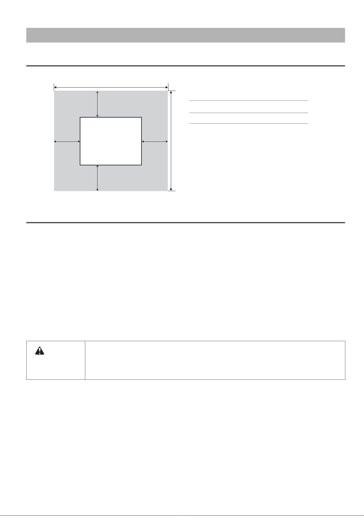
Install the product in an environment that satisfies the conditions in the table below.
Installation environment conditions
Power supply
specifications
Printer Voltage: AC 100 V to 240 V ±10%
Frequency: 50/60 Hz ±1 Hz
Capacity: No less than 3 A
Heater ×2 Voltage: AC 100 V to 120 V ±10% / AC 200 V to 240 V ±10%
Frequency: 50/60 Hz ±1 Hz
Capacity
• Heater 1: No less than 10 A (AC 100V to 120V)
• Heater 1: No less than 10 A (AC 200V to 240V)
• Heater 2: No less than 10 A (AC 100V to 120V)
• Heater 2: No less than 0 A (AC 200V to 240V)
Environmental
conditions
Operating environment Temperature 20 to 28 °C, Humidity 40 to 60%
No condensation
Recommended Printing
Environment
Temperature 22 to 28 °C, Humidity 40 to 60%
No condensation
Environment for storage • Storage without ink charging: up to 6 months
Temperature -20 to +60 °C, Humidity 20 to 80%
• Storage with ink charging: up to 30 days *1*2
Temperature 5 to 30 °C, Humidity 20 to 80%
*1Perform the Daily Maintenance instructed in the Operation
manual.
*2Always leave the printer in sleep mode and check the
remaining ink level once a week.
Agitate ink in the cartridge once a week as instructed.

8 Assembling
Assembling
Follow the procedure below to assemble the stand.
Assemble the printer
Four or more people are required to assemble this printer.
Procedure for assembling the stand
[1] Assemble the right stand.
[2] Attach the right leg part to the right base part so that four screw holes
in the base part are at the front.
[3] Tighten two hexagon socket head cap screws using a hexagonal wrench (supplied accessory).
[4] Assemble the left stand in the same way as in Step 2, 3.
[5] Fasten the connector bar to the right stand using two hexagon socket
head cap screws.
• Attach the connector bar with the groove facing the rear as shown
left.
Assembling
CAUTION
Leg (right)
Base
Hexagon socket head cap
screws
Screw holes
Front
Screw holes
Front
Leg (left)
Base
Hexagon socket head cap
screws
Stand (right)
Connector bar
Hexagon socket
head cap screws the groove surface
Front

Assembling 9
Follow the procedure below to attach the stand to the printer.
[6] Fasten the connector bar to the left stand in the same way as in Step 5.
[7] Attach the waste fluid tank holder to the right stand using four screws.
[8] Shake the stand to make sure that each part is firmly attached.
Procedure for attaching the stand
[1] Turn the four adjusters as shown below to prevent the stand from
moving.
[2] Insert the two transfer stays into the right and left transfer brackets, lift
the printer with four or more people and place it on the stand.
[3] Remove the two transfer stays and fasten the printer to the stand
using eight butterfly screws.
• 1: Transfer stays
•2:Stand
•3:Butterflyscrews
Stand (left)
Connector bar
Hexagon socket
head cap screws
Front
Stand (right)
Screws
Waste uid tank holder
Stand
Adjusters Adjusters
Stand
Transfer stay Transfer stay Transfer bracket
2
3
3
3
2
3
3
3
1
1

10 Assembling
Follow the procedure below to attach the waste fluid tank.
Procedure for attaching the waste fluid tank
[1] Place the waste fluid tank in the waste fluid tank holder.
[2] Attach the waste fluid tube to the tank.
• Attach the waste fluid tube to the tank.
• Pull out the absorbent material tray.
Important!
Make sure the inner tube is fully inserted into the waste fluid tank.
If not, waste ink may be spilled from the tank.
Insert the waste fluid sensor cable into the connector on the bottom
of the printer.
[3] Confirm that the waste fluid valve is closed.
Waste fluid tank
Waste fluid
tube
Absorbent
material tray
Waste fluid sensor
connector
Waste fluid sensor cable
Waste fluid valve

Assembling 11
Follow the procedure below to detach all protective materials.
Detaching fastening materials
[1] Remove all tapes from each cover.
[2] Open the front cover and remove all protection materials fixed with tape.
[3] Peel off the tape, be careful not to come in contact with T fence, and
remove the Bearer collapse prevention material and Bearer fix.
Important!
Make sure not to damage T fence during operation. If T fence is damaged,
it will affect print results.
[4] Remove the tape, and move the media holder plates to the left and
the right edge.
[5] Raise the media loading lever.
[6] Peel off the tape, and remove the protective material from the head
strike prevention sensor.
T fence
Media holder plate

12 Assembling
[7] Remove a screw from the carriage bracket and then remove the
bracket.
[8] Close the front cover.
[9] Open the right maintenance cover.
Remove the cushioning material from the printer.
• Close the maintenance cover.
[10] Open the left maintenance cover, then place the tray.
• Close the maintenance cover.

Assembling 13
Checking the levelness
[1] Turn the following adjusters in the direction as shown left to prevent
the printer from moving.
[2] Open the front cover.
[3] Set the level on the right and left platens and adjust so that the printer
stays flat.
Level

14 Assembling
To print on a rigid media, follow the steps below to assemble the media-feed tables.
Assembling the media-feed table (optional)
[1] Use hexagon socket head cap screws (4 pieces) to fix the
reinforcement between the legs (right and left).
• Place the convex sections of the legs (right and left) along the notch
of the reinforcement to assemble.
[2] Place the Frame on the legs and fix it with four hexagon socket head
cap screws.
• Firmly insert the protruding portions of the legs to the holes of the
Frame to fix it.
[3] Use the lug screw to fix Stopper on Frame.
• Install Stopper on the side of rail retaining screw.
• Install Stopper so that the curved part matches Frame.
[4] Use the screws (2 pieces each) and fix Installation plates (R and L) on
Frame.
• Install Installation plates on the opposite side of rail fixing screw.
Reinforcement
Leg (Left)
Leg (Right)
Hexagon socket head cap screw
Frame
Hexagon socket
head cap screw
Stopper
Lug screw
Rail retaining
screw
Screw
Screw
Installation plates (R)
Installation plates (L)

Assembling 15
Before printing on a rigid media, follow the steps below to install the media-feed tables.
Required items:
• Hexagonal spanner (supplied with the media-feed table)
• Level (supplied with the printer)
Attaching the media-feed table (optional)
Rear side procedure
[1] Loosen the fixing levers on the right and left side of the rear. Set the
distance between the roll media holders wider than the roll media
width.
[2] Check that the leveling screws on the left and right side of the table
are tightened.
Note
When fixing the leveling screws, hold the frame while pressuring the rubber foot, and
then turn the screw until it doesn’t turn any further.
[3] Insert the positioning guide of Media-feed table into the square hole of Paper guide R.
Positioning guide
Square hole

16 Assembling
[4] Turn the screws on the caster of Media-feed table (2 places, ones closer to the printer) with a spanner.
Adjust so that there is a 6 mm gap between the top side of the square hole of Paper guide R and the top side of the
positioning guide.
Note
• Caster of Media-feed table has two types of screws. Turn the bottom screw.
• Turn the screw clockwise to raise Media-feed table.
[5] Place the level at the edge of printer’s platen, and check the position of the air bubble.
[6] Place the level on the frame of Media-feed table.
Place the level on the same side as when you placed it on the printer.
6 mm
Positioning guide
Platen
Level
Level
Frame

Assembling 17
[7] Turn the screw of Media-feed table’s caster (the one further from the printer) with a spanner, and adjust the slant.
Make sure that the position of the level’s air bubble is at the same position as when you place it on the printer.
[8] Adjust the slant on the other side in the same way.
Front side procedure
[1] Check that the leveling screws on the left and right side of the table
are tightened.
Note
When fixing the leveling screws, hold the frame while pressuring the rubber foot, and
then turn the screw until it doesn’t turn any further.
[2] Insert the positioning guide of Media-feed table into the square hole of Paper guide F.
Level
Positioning guide
Square hole

18 Assembling
[3] Turn the screws on the caster of Media-feed table (2 places, closer to the printer) with a spanner.
Adjust so that there is a 6 mm gap between the top side of the square hole of Paper guide F and the top side of the
positioning guide.
Note
• Caster of Media-feed table has two types of screws. Turn the bottom screw.
• Turn the screw clockwise to raise Media-feed table.
[4] Place the level at the edge of printer’s platen, and check the position of the air bubble.
[5] Place the level on the frame of Media-feed table.
Place the level on the same side as when you placed it on the printer.
6 mm
Positioning guide
Level
Platen
Level
Frame

Assembling 19
[6] Turn the screw of Media-feed table’s caster (the one further from the printer) with a spanner, and adjust the slant.
Make sure that the position of the level’s air bubble is at the same position as when you place it on the printer.
[7] Adjust the slant on the other side in the same way.
Level

20 Connecting the cables
Connecting the cables
Connecting power cable
1. Before connecting the cables...
[1] Close the front cover.
[2] Make sure that the printer is turned off.
Note
If the power switch is in a pressed-inward state, it is turned on and you must press it
again to turn it off.
[3] Make sure that the blower heater is turned off.
Connecting the cables
Check!
OFF
Table of contents
Other Muton Printer manuals

Muton
Muton XPJ-1641SR User manual

Muton
Muton XPJ-1642WR User manual

Muton
Muton XPJ-1682WR User manual

Muton
Muton XPJ-1682D User manual

Muton
Muton ValuejetVJ-1604 User manual

Muton
Muton VJ-1626UH User manual

Muton
Muton VJ-1608 Hybrid User manual

Muton
Muton XPJ-1642WR User guide

Muton
Muton XPJ-461UF User guide
Popular Printer manuals by other brands

Samsung
Samsung ML-2551N user guide

Canon
Canon Pixma iP6000 installation instructions

Konica Minolta
Konica Minolta magicolor 7450 installation guide

Stahl
Stahl Hotronix DUAL Air Fusion Operator's manual

Epson
Epson WorkForce WF-M1030 Start here

Infinite Peripherals
Infinite Peripherals PP-50 Developer's guide