SH - NLFREN - v1.1 - 01122016
4
NL
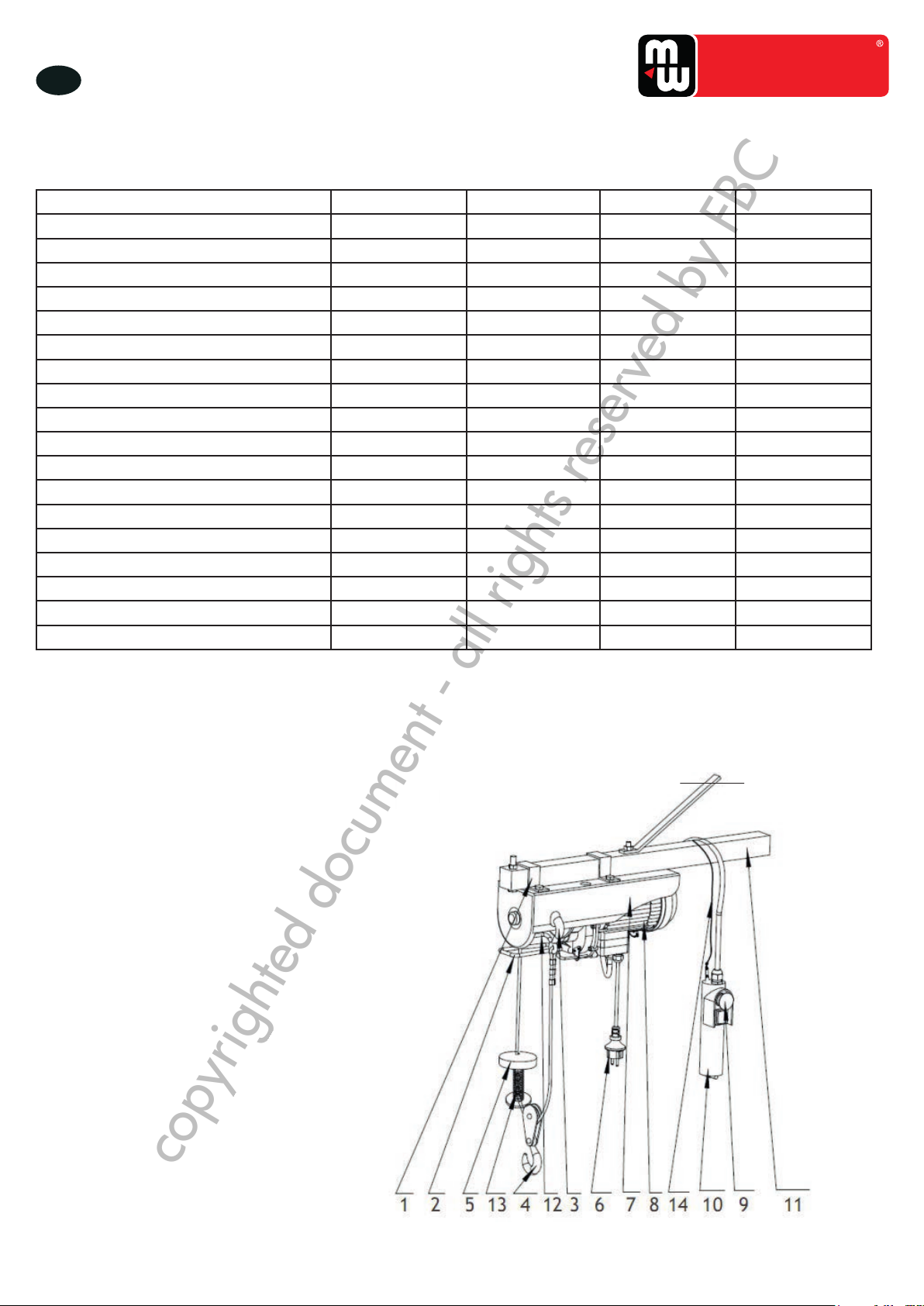
TOOLS
4 Toepassingsgebied
• Deze takel is geschikt voor het optillen en neerlaten van lasten.
• Het is verboden mensen of dieren op te tillen.
• De lasten moeten altijd verticaal opgetild worden.
• Elk ander gebruik is verboden.
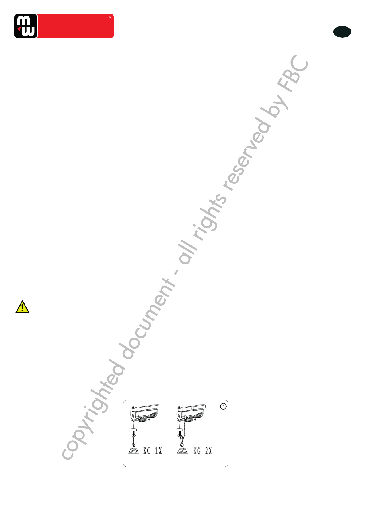
• Als het vermogen te laag is om een last op te tillen, controleer of de netspanning 230 V bedraagt. De takel werkt optimaal
met een 230 V spanning. Als de spanning lager is, verminder de belasting.
5 Voorbereiding
Voor het begin van het werk, moeten sommige voorbereidingsoperaties uitgevoerd worden:
• Maak zeker dat de kenmerken van het stroomnet met deze van het toestel overeenstemmen, en dat het toester met een
stekker is uitgerust.
• Maak een test zonder last, en controleer de volgende punten:
a. De exibiliteit van de “Op/Neer knop (up/down), voor een goede controle van de beweging van de lasthaak,
b. De werking van de bovenste stop, die de stroomtoevoer onderbreekt,
c. De werking van de onderste stop, die de stroomtoevoer onderbreekt als de kabel bijna ontrold is,
d. Abnormale geluiden tijdens de werking,
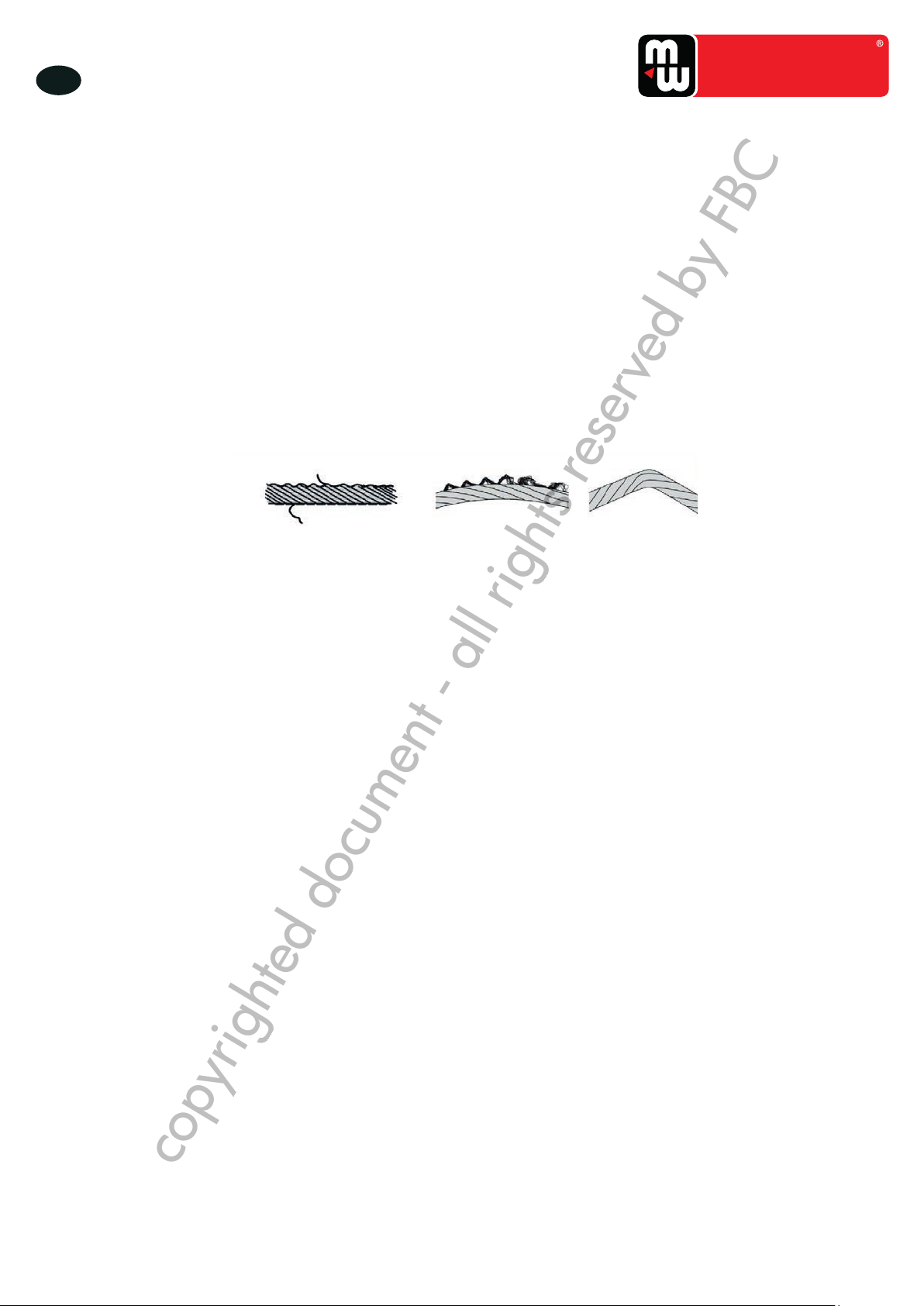
e. Als de stalen kabel beschadigd is (gerafeld of gebogen), of als hij 20 werkuren heeft bereikt, vervang deze.
• Controleer het remschijf alle 20 werkuren. Als de last niet goed gehouden is, of als de rem niet soepel werkt, vervang de
beschadigde onderdelen onmiddellijk.
• Controleer de haak voor gebruik, en vervang deze als beschadigd of vervormd.
• Het toestel is met een reststroom beveiliging uitgerust (rode noodstop knop), die extra bescherming biedt in geval van
gevaar en in noodsituaties. Nadat de noodstop werd geactiveerd, draai de knop in de richting van de pijl, om deze te
ontgrendelen nadat het gevaar verwijderd is.
• Zorg voor een voldoende smering van de onderdelen. Smeer de haak, de kabeltrommel, de vertragingsdoos en de lagers
alle zes maanden.
• Smeer de houder van de as van de trommel wanneer u de stalen kabel vervangt. Vervang de kabel onmiddellijk als deze
beschadigd is.
• Ontkoppel de takel van de stroomtoevoer voor het onderhoud of reparatiewerken.
• Voor de ingebruikname, controleer de takel op transportschade. Als er een probleem is neem onmiddellijk contact op met
uw verdeler.
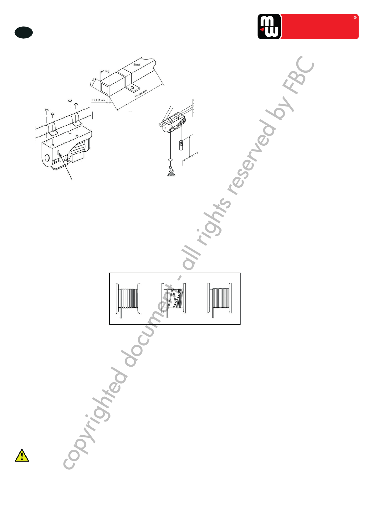
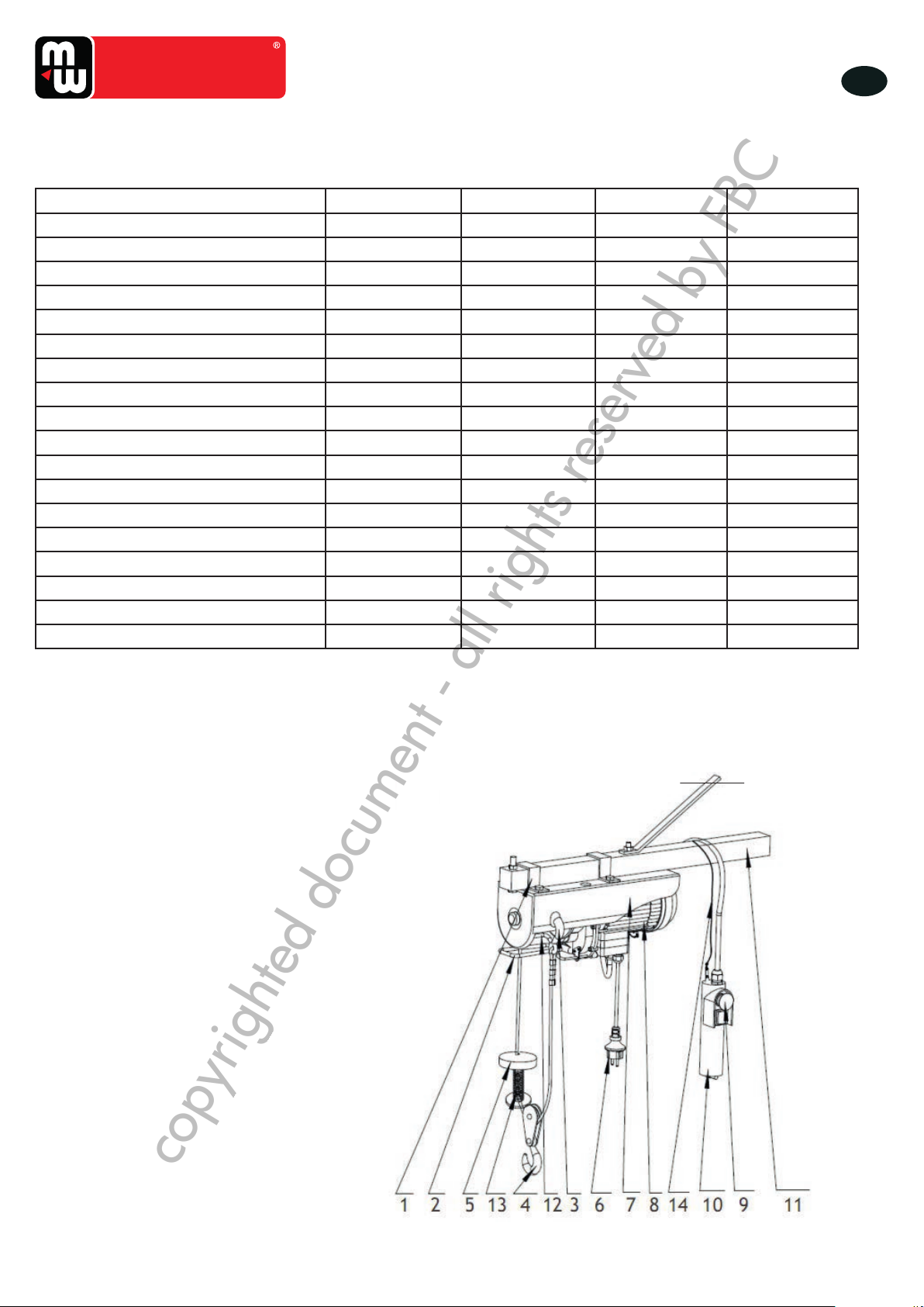
6 Installatie
1. Installeer de takel op een stalen balk (zie afb. 2). Gebruik enkel de meegeleverde houder, die aan de bovenkant van de
behuizing bevestigd kan worden door middel van de schroeven, sluitringen en veerringen. De stalen balk moet tenminste
tweemaal het gewicht van het toestel kunnen dragen. Contacteer een professionele installateur voor het beste resultaat.
2. De stalen balk moet een minimale diameter van 46 mm hebben, een wanddikte van tenminste 2,3 mm en een lengte van
tenminste 450 mm (zie afb. 2, onder).
3. De stalen balk moet stevig in de muur bevestigd zijn. De bevestiging moet stevig genoeg zijn om de last te dragen.
4. Maak zeker dat de takel horizontaal wordt geïnstalleerd, en niet schuin.
5. De afstandbediening moet op elk ogenblik bereikbaar zijn, en moet dus op een afstand tussen 0,8 m en 1,5 m van de
grond geïnstalleerd worden (zie afb. 3, boven).
6. Steek de lasthaak in de haakhouder van de behuizing, wanneer u een extra haak gebruikt met een afwijkende as.
7. De elektrische riemschijf moet aan de bovenkant bevestigd worden. Bevestig de riemschijf met het frame op de dwarsbalk.
De balk wordt vervolgens op de steunkolommen bevestigd. De kolommen moeten op de werkoppervlak bevestigd worden,
volgens de behoeften van de gebruiker. Ze moeten stabiel en stevig bevestigd worden. Ze moeten ook in staat zijn
langdurig te weerstaan aan de nominale belasting.
Technical Specifications
Type YT-125/250-A YT-300/600 YT-500/999
capacity
-for single cable
125 kg
250 kg300 kg
600 kg
500 kg
999kg
Cable speed
-for single cable
-For double cable
8m/min
4m/min 8m/min
4m/min 8m/min
4m/min
Sound pressure
level (LWA)
71 dB(A) 71 dB(A) 71 dB(A)
•The LWA valuesstated here only indicate the loudness emitted by this machine.Whether the operator
is required to wear hearing protection can’tbe determined here.This depends on how much noise
reaches the ear of the operator.And this,among other things,depends on the existing ambient
conditions (such as other sources of noise nearby).Even though it may not be explicitly required,it is
in your own interest to always wear hearing protection when operating this machine.
YT-125/250-A, YT-300/600
YT-500/999
Electric Principle Drawing
Be sure to fix 10 Amp fuse or air switch on the loop of power supply when using this cable winch.
Environmental Protection
Discarded electric appliances are recyclable and should not be discarded in
the domestic waste! Please actively support us in conserving resources
and protecting the environment by returning this appliance to the collection
centres (if available).
Schakelschema
Zorg ervoor, dat er een 10 A zekering of een
veiligheidsschakelaar op de stroomvoeding is bij het gebruik
van het toestel.
copyrighted document - all rights reserved by FBC