3
M1.2.PPH20B.NLFREN - 05032019
FR
1 Sécurité
• Ne pas utiliser la presse pour d’autres usages que ceux pour lesquels elle a été conçue.
• Ne pas travailler sur les pièces à presser lorsque le piston est en mouvement ou sous pression.
• La soupape de sécurité est tarée et plombée par le constructeur: Ne pas tenter de la démonter ou d’en modier le réglage.
• Le non-respect de ces recommandations peut causer les dommages, mêmes graves, à la personne et/ou personnes qui
travaillent avec la presse.
• Le constructeur décline toute responsabilité en cas de dommages qui pourraient être causés aux personnes ou aux biens
par suite d’une utilisation impropre de la presse ou de ses accessoires.
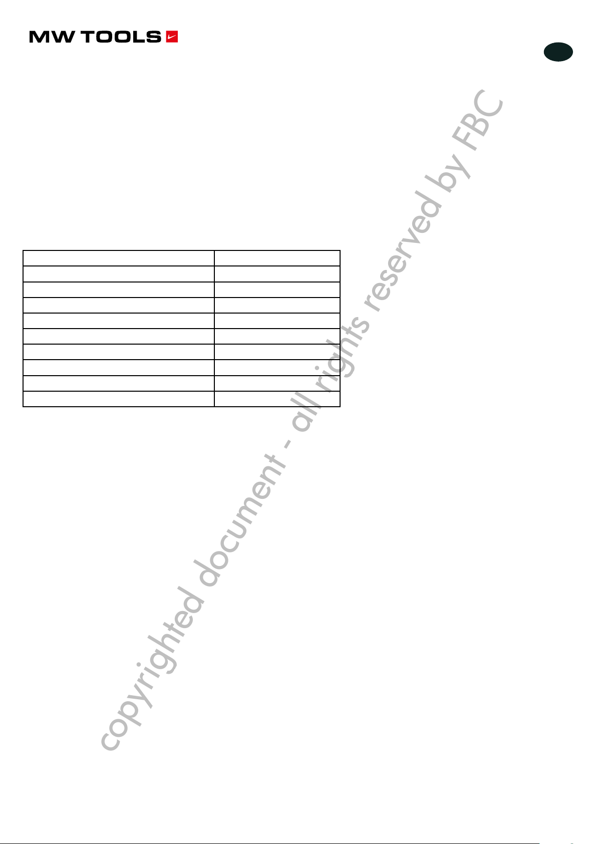
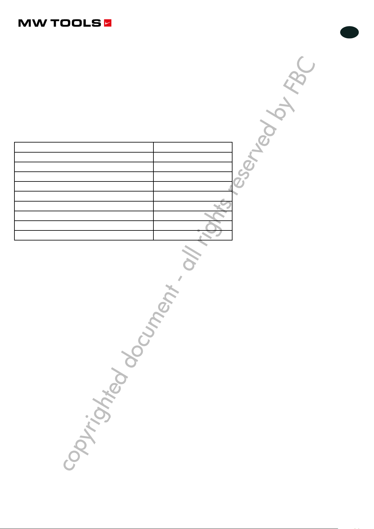
2 Données techniques
Modèle PPH20B
Capacité 20 t
Course du cylindre 176 mm
Distance minimale de la pièce 45 mm
Pression d’air requise 8 bars
Course 185 mm
Vitesse montée sous pression / sans pression 62 / 185 mm/min
Vitesse descente sous pression / sans pression 370 /185 mm/min
Dimensions (L x l x h) 725 x 270 x 1740 mm
Poids net 151 kg
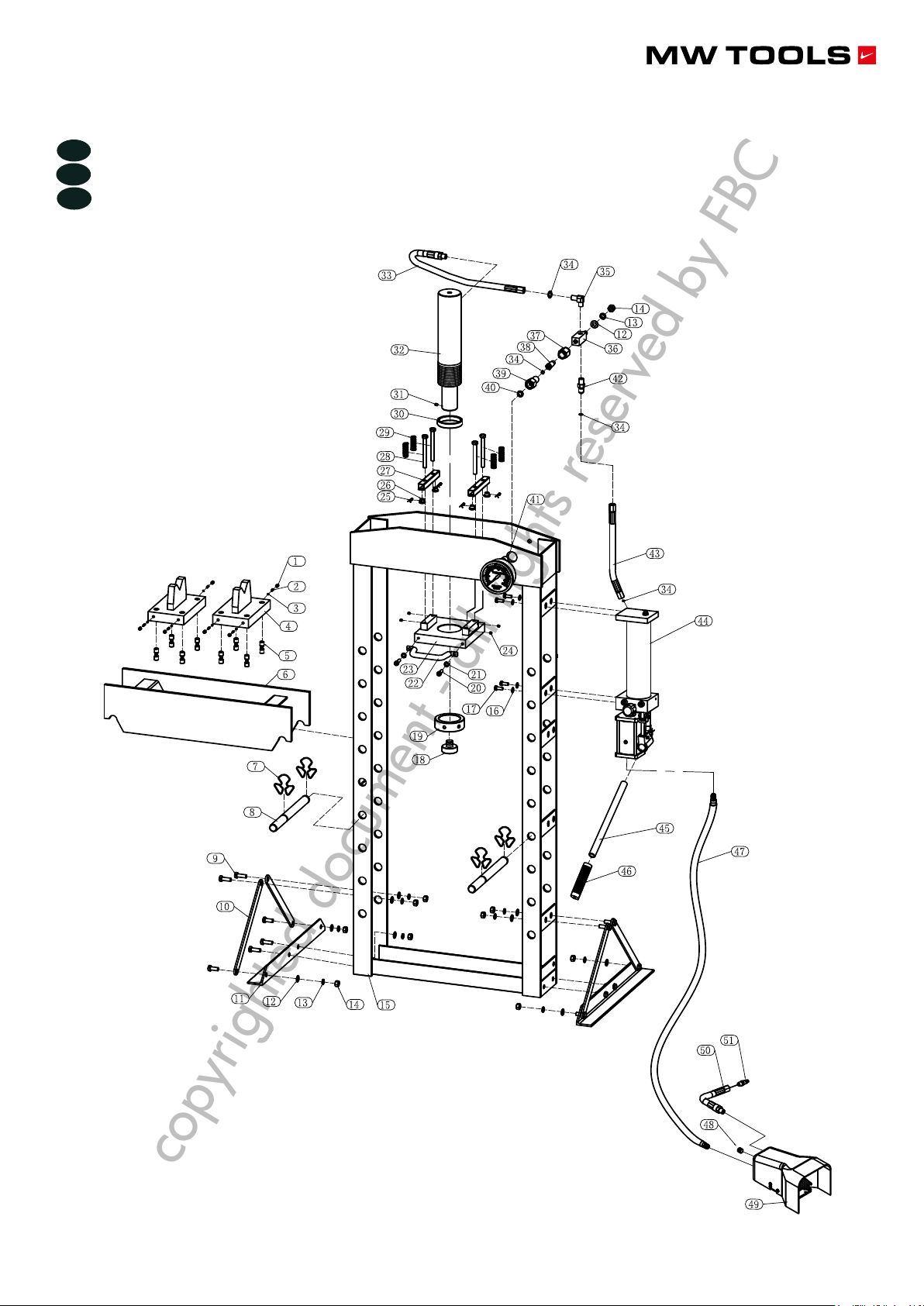
3 Utilisation
• Assurez-vous que le châssis est à la position minimum et que le treuil est lâché.
• Mettez le bloc de talon (4) sur le châssis (6), insérez ensuite l’objet sur le bloc de talon. Fermez la soupape de décharge
(P20) en la tournant dans le sens horaire jusqu’à ce qu’elle soit bien fermée.
• Connectez le raccord rapide du tuyau d’air (51) au raccord de la source d’air, ouvrez la soupape d’air (49) pour faire
fonctionner la pompe jusqu’à ce que la selle dentelée (18) s’approche de l’objet, arrêtez ensuite la soupape d’air.
• Si aucune source d’air n’est disponible, pompez avec la poignée (45) jusqu’à ce que la selle dentelée (18) s’approche de
l’objet. Alignez l’objet et le mandrin pour centrer la pression. Ouvrez la soupape d’air (ou pompez avec la poignée) pour
appliquer la pression sur l’objet.
• Quand le travail est terminé, arrêtez la soupape d’air (ou cessez de pomper avec la poignée), retirez lentement et
prudemment la pression de l’objet en tournant la soupape de décharge (P20) dans le sens contraire des aiguilles d’une
montre par petites étapes. Une fois que le mandrin s’est entièrement rétracté, retirez l’objet du châssis de la presse.
• Déconnectez le raccord d’entrée d’air de la source d’air.
4 Entretien
• Huilez les parties mobiles tous les six mois et contrôlez le bon fonctionnement du manomètre.
• Tous les six mois, graissez le treuil et les câbles. Ces derniers devront être contrôlés visuellement sur toute leur longueur et
remplacés s’il présentent le moindre défaut.
• L’unité hydraulique (pompe/vérin) est un système fermé qui, en utilisation normale, ne demande qu’une lubrication
semestrielle des parties mobiles. Dans le cas où l’unité hydraulique présenterait une fuite d’huile et serait démontée pour
remplacement des joints, il sera nécessaire de refaire le plein d’huile par l’orice de remplissage situé sur la pompe,
jusqu’à ce que le niveau de l’huile atteigne le bord de l’orice. Cette opération doit être faite avec le piston du vérin en
position de repos, c’est à dire complètement rentré. L’huile de l’unité hydraulique doit, de toutes façons, être remplacée tous
les deux ans, quel que soit l’état de l’unité hydraulique. Utilisez de l’huile hydraulique de viscosité 22°E à 25°E.
copyrighted document - all rights reserved by FBC