MW TOOLS CAT415 User manual

M1.1.CAT415.NLFREN 14062018
HANDLEIDING - MODE D’EMPLOI - MANUAL
CAT415 (754751444)
Zandstraalcabine
Cabine de sablage
Sandblast cabinet
P.02 Gelieve te lezen en voor later gebruik bewaren
P.07 Veuillez lire et conserver pour consultation ultérieure
P.12 Please read and keep for future reference
FR
EN
NL
copyrighted document - all rights reserved by FBC

M1.1.CAT415.NLFREN 14062018
2
NL
1 Inleiding
De zandstraalcabine CAT415 heeft twee zijdeuren en een elektrisch-pneumatisch bedieningssysteem. Met een grote, goed
afgesloten cabine, een transparant glazen zichtvenster en rubberen handschoenen, geschikt voor zwaar werk, is ze gemakkelijk
en veilig om mee te werken en echt een milieuvriendelijk product voor diverse toepassingen.
Er worden 2 straalpistolen bijgeleverd, het ene met een vaste exibele metalen buis, die vrij van richting kan veranderen en
bediend wordt met een pedaalschakelaar, het andere, handbediend en beweegbaar, wordt aangebracht als een hulppistool
als alternatief voor de gebruiker. Met een luchtdrukbereik tussen 4 bar (60 Psi) en 8 bar (120 Psi) voor het aanleveren van de
straalmiddelen kan de cabine gebruikt worden voor verschillende oppervlaktebehandelingen en decoratieve doeleinden, zoals
verwijderen van roest, verf, schilfers of andere vreemde aantasting van metaal of voor het maken van grove patronen op glas.
2 Technische kenmerken
1. Algemene afmetingen: 1000 x 610 x 1630 mm
2. Werkruimte: 945 x 605 x 605 mm
3. Luchtdruk: 4 bar - 8 bar (60 Psi - 120 Psi)
4. Straalmiddelcapaciteit: ongeveer 18 kg
5. Straalmiddelen: Siliciumzand, glasparels, siliciumcarbide, normaal korund, plasticzand, enz.
6. Stroomvereisten: 110 V/60 Hz of 230 V 50 Hz
7. Voltage uit: 12 V
Inhoud
1 Inleiding................................................................................................................................................................2
2 Technische kenmerken.............................................................................................................................................2
3 Instructies voor de montage .....................................................................................................................................3
4 Aansuiting van de luchttoevoer.................................................................................................................................3
5 Installatie van het vaste pistool .................................................................................................................................3
6 Installatie van het beweegbare pistool.......................................................................................................................3
7 Instructies voor de bediening ...................................................................................................................................4
8 Verlichting en elektrisch-pneumatisch systeem .............................................................................................................4
9 Functiebeschrijving van onderdelen voor bediening en controle....................................................................................5
10 Instructies voor het gebruiken van de elektrische bediening ........................................................................................5
11 Hoe het straaleffect onder controle houden ..............................................................................................................5
12 Onderhoud .........................................................................................................................................................5
13 Problemen oplossen..............................................................................................................................................6
14 Elektrisch schema ...............................................................................................................................................17
15 Onderdelen.......................................................................................................................................................18
16 EG conformiteitsverklaring ...................................................................................................................................19
copyrighted document - all rights reserved by FBC

M1.1.CAT415.NLFREN 14062018
3
NL
3 Instructies voor de montage
1. Verwijder alle onderdelen uit de cabine, alsook van het vloerrooster uit de bodem van de kist, onder het karton.
2. Verwijder alle onderdelen uit de cabine.
3. Zet de cabine ondersteboven
4. Maak de poten vast met 4 1/4 x 1/2” bouten.
a. Op de linkervoorpoot hangt het naamplaatje
b. Voor de achterpoten heeft u ook 2 zelftrekkende schroeven nodig.
5. Zet de cabine rechtop
6. Zet de voetpedaal tussen de voorpoten
7. Maak de deuren vast met 4 moeren
8. Los de bouten op de deurhendels, beweeg ze naar het uiterste punt en maak de bouten weer vast. Ze iets naar binnen
bewegen zal de afdichting van de deur dicht maken.
9. Plaats het glas op de cabine.
10. Plaats de lichtarmatuur op het glas met de schakelaar aan de rechterkant. Maak aan de cabine vast met 4 1/4 x 3/4”
bouten en platte sluitringen.
11. Stofafzuiging
a. Maak de stofafzuiging vast aan de achterkant (rechts) met 1/4 x 3/4”bouten en platte sluitringen.
b. Plaats de bovenkant van de stofafzuiging (met de motor en de lter) erop en doe de 2 hendels naar boven.
c. Neem de zuigmond van de stofafzuigslang binnen in de cabine af en maak de buis vast. Zet de zuigmond terug.
12. Maak alle bouten, moeren en schroeven vast.
13. Plaats het vloerrooster met de uitgesneden hoek naar de rechter voorkant van de cabine. Steek de slangen door de
opening.
14. Steek de stekker van de stofafzuiging in het contact dat vanuit de verlichting komt. Steek de stekker van de verlichting in
een 115 V/60 Hz stopcontact. Zet de schakelaar van de afzuiging aan, de schakelaar op de cabine zal het licht en de
stofafzuiging aanzetten.
15. Doe straalmiddel in de cabine door het vloerrooster (ongeveer 1/4 zak).
4 Aansluiting van de luchttoevoer
1. Haal de zelfsluitende aansluiting uit de binnenverpakking. Wikkel tape rond de draad van de aansluiting. Schroef hem in
de luchtinlaat aan de achterkant van het elektrische bedieningspaneel en maak vast.
2. Duw het koppelstuk van de zelfsluitende aansluiting naar de luchtinlaat tot u een kegelvormige uiteinde ziet. Steek dit in
de slang van de compressor en klem het vast. Duw nogmaals tegen het koppelstuk en duw het in de andere kant van het
kegelvormige uiteinde. Laat los en de koppeling is verzekerd.
5 Installatie van het vaste pistool
1. Verwijder de zuigkop van het vaste pistool en steek er een luchtspuit in. Maak de zuigkop weer vast. Maak de M6 schroef
op de zijkant van het pistool los en installeer de bijhorende spuitkop. Maak de schroef terug vast
2. Verbind de zijarm van het pistool met een afzuigslang. Verbind de achterste ingang van het pistool met de exibele
metalen buis in de cabine. Schroef ze vast.
3. Maak de andere kant van de afzuigslang vast aan de passende afzuigbuis.
6 Installatie van het beweegbare pistool
1. Maak een kant van de hoge-druk luchtslang vast aan de luchtkoppeling aan de rechterkant van het elektrische
bedieningspaneel en de andere aan de luchttoevoer van het beweegbare pistool.
2. Maak een kant van de zuigslang vast aan de zijkant van het beweegbare pistool, de andere aan de vaste afzuigbuis.
3. De installatie van de luchtspuit en spuitkop zijn dezelfde als bij het vaste pistool.
4. Plaats het beweegbare pistool op het mazenschrerm.
copyrighted document - all rights reserved by FBC

M1.1.CAT415.NLFREN 14062018
4
NL
7 Instructies voor de bediening
1. Luchtspuit en spuitmond moeten in grootte overeenkomen.
2. Giet ongeveer 18 kg schuurmiddel in de trechter via de zijdeur van de cabine.
3. Plaats een lter op de ens aan de zijkant van de cabine en verbind met een stofafzuiging. Dit voorkomt dat stof de motor
binnendringt en de machine beschadigt.
4. Als de luchtdruk van de compressor 4 bar (60 Psi) bereikt, zet de schakelaar dan op “ON”. Het indicatielampje zal
beginnen branden.
5. Deze machine wordt geleverd met twee pistolen, maar met het elektrisch-pneumatisch bedieningssysteem kunnen ze niet
tegelijk gebruikt worden. Als het lampje voor het beweegbare pistool brandt, is dat beschikbaar om mee te werken. Als
het lampje voor “deuren gesloten” brandt, duw op de pedaalschakelaar en het vaste pistool zal onmiddellijk werken. Het
lampje voor het beweegbare pistool gaat dan ook uit.
6. Er is een sensor aangebracht aan de binnenkant van de deur om te controleren of de deur open of dicht is. Als het lampje
“deuren gesloten” niet brandt, zal het vaste pistool niet werken, ongeacht of de pedaalschakelaar ingedrukt wordt of niet.
7. Als de luchtdruk hoger is dan 4 bar (60 Psi) kan er een test gedaan worden. Steek de handen in de rubber handschoenen,
neem het werkstuk vast, breng het in positie onder het vaste pistool, stap op het pedaal en het straalproces begint. U kan
ook met het beweegbare pistool werken. Controleer na een tijdje het effect op het oppervlak van het werkstuk.
8. Het straalmiddel zal na het stralen op de bodem van de trechter vallen en kan opnieuw gebruikt worden.
Noot: De gebruikte lucht moet droog genoeg zijn, gebruik anders een waterlter om het water op te vangen voor het de
elektrische bediening binnengaat.
8 Verlichting en elektrisch-pneumatisch systeem
Het pneumatische systeem wordt door een elektrisch circuit bediend, dat zich in een doos op de cabine bevindt.
Zo ziet het frontpaneel van de elektrische bediening eruit:
1Zekering 2 Stroomschakelaar
3Lichtschakelaar 4 Schakelaar stofafzuiging
5 Controlelampje stroomtoevoer 6 Controlelampje
7Controlelampje “Deuren gesloten” 8 Vast pistool controlelampje
9 Beweegbaar pistool controlelampje 10 Luchtdrukmeter
11 Luchtdrukklep
CAT415 - NLFREN - v1.0.1 - 21042017
4
NL
TOOLS
7 Instructies voor de bediening
1. Luchtspuit en spuitmond moeten in grootte overeenkomen.
2. Giet ongeveer 18 kg schuurmiddel in de trechter via de zijdeur van de cabine.
3. Plaats een lter op de ens aan de zijkant van de cabine en verbind met een stofafzuiging. Dit voorkomt dat stof de motor
binnendringt en de machine beschadigt.
4. Als de luchtdruk van de compressor 4 bar (60 Psi) bereikt, zet de schakelaar dan op “ON”. Het indicatielampje zal
beginnen branden.
5. Deze machine wordt geleverd met twee pistolen, maar met het elektrisch-pneumatisch bedieningssysteem kunnen ze niet
tegelijk gebruikt worden. Als het lampje voor het beweegbare pistool brandt, is dat beschikbaar om mee te werken. Als
het lampje voor “deuren gesloten” brandt, duw op de pedaalschakelaar en het vaste pistool zal onmiddellijk werken. Het
lampje voor het beweegbare pistool gaat dan ook uit.
6. Er is een sensor aangebracht aan de binnenkant van de deur om te controleren of de deur open of dicht is. Als het lampje
“deuren gesloten” niet brandt, zal het vaste pistool niet werken, ongeacht of de pedaalschakelaar ingedrukt wordt of niet.
7. Als de luchtdruk hoger is dan 4 bar (60 Psi) kan er een test gedaan worden. Steek de handen in de rubber handschoenen,
neem het werkstuk vast, breng het in positie onder het vaste pistool, stap op het pedaal en het straalproces begint. U kan
ook met het beweegbare pistool werken. Controleer na een tijdje het effect op het oppervlak van het werkstuk.
8. Het straalmiddel zal na het stralen op de bodem van de trechter vallen en kan opnieuw gebruikt worden.
Noot: De gebruikte lucht moet droog genoeg zijn, gebruik anders een waterlter om het water op te vangen voor het de
elektrische bediening binnengaat.
8 Verlichting en elektrisch-pneumatisch systeem
Het pneumatische systeem wordt door een elektrisch circuit bediend, dat zich in een doos op de cabine bevindt.
Zo ziet het frontpaneel van de elektrische bediening eruit:
1Zekering 2 Stroomschakelaar
3Lichtschakelaar 4 Schakelaar stofafzuiging
5 Controlelampje stroomtoevoer 6 Controlelampje
7Controlelampje “Deuren gesloten” 8 Vast pistool controlelampje
9 Beweegbaar pistool controlelampje 10 Luchtdrukmeter
11 Luchtdrukklep
copyrighted document - all rights reserved by FBC

M1.1.CAT415.NLFREN 14062018
5
NL
9 Functiebeschrijving van onderdelen voor bediening en controle
1Zekering Zorgt voor bescherming tegen overbelasting en kortsluiting
2 Stroomschakelaar Om de stroom in of uit te schakelen
3Lichtschakelaar Om het licht aan of uit te doen
4 Stofschakelaar Om de stofafzuiging aan of af te zetten
5Controlelampje “deuren gesloten” Als het brandt, zijn de deuren dicht en kan met het vaste pistool
gewerkt worden.
6 Controlelampje vast pistool Als het brandt, werkt het vast pistool
7 Controlelampje beweegbaar pistool Als het brandt, werkt het beweegbare pistool
8 Luchtdrukmeter Duidt de luchtdruk voor het stralen aan
9 Luchtdrukklep Regelt de luchtdruk waarmee gewerkt wordt. Draaien in
wijzerzin verhoogt de druk, in tegenwijzerzin verlaagt de druk.
10 Pedaalschakelaar Bedient de werking van het vaste pistool
11 Elektromagnetische klep Regelt het wisselen van de luchtuitlaat
10 Instructies voor het gebruiken van de elektrische bediening
1. Steek de stekker in een geaard stopcontact.
2. Zet de stroomschakelaar op “ON”, het controlelampje begint onmiddellijk te branden. Indien niet, controleer dan de
stroomvoorziening , de kabel en de zekering. Gebruik indien nodig vervangstukken van hetzelfde type.
3. Zet de lichtschakelaar op “ON”, het licht begint onmiddellijk te branden.
4. De sensor voor “deuren gesloten” beschermt de operator en de directe omgeving tegen de straalmiddelen. Als het
controlelampje brandt, zijn de deuren goed dicht en kan met het vaste pistool gewerkt worden.
5. Als het bedieningssysteem uitvalt of er iets niet goed werkt, laat het dan door een gespecialiseerde technieker herstellen.
11 Hoe het straaleffect onder controle houden
1. Kies afhankelijk van hoe jn u het werkstuk wil zandstralen de juiste spuitmond en luchtspuit.
2. Gebruik de juiste dikte van schuurmiddel. Omdat het slijt tijdens het straalproces, wordt aangeraden een dubbele laag van
gewoon venster te gebruiken om het straalmiddel te weerstaan na enige tijd.
3. Beweeg het werkstuk of het pistool gelijkmatig en in draaiende bewegingen tijdens te stralen.
4. De luchtdruk moet tijdens het werken stabiel blijven.
5. Zorg voor een goede verlichting om een goed overzicht van de cabineruimte te hebben.
12 Onderhoud
1. De luchtslangen mogen niet geblokkeerd, gedraaid of met kracht samengedrukt worden.
2. Deeltjes straalmiddel kunnen tussen de deurafsluiting raken. Gebruik een zachte borstel om ze na verloop van tijd weg te
vegen.
3. Als de zichtbaarheid in de cabine vermindert, vervang dan de beschermende lm op het kijkvenster.
4. Als het stralen gedaan is, verwijder dan resterende straalmiddelen tussen luchtspuit en spuitmond.
copyrighted document - all rights reserved by FBC

M1.1.CAT415.NLFREN 14062018
6
NL
13 Problemen oplossen
Probleem Oorzaak Oplossing
Verminderde
straalmiddelenstroom
Straalmiddel vast in spuitmond 1. Nat straalmiddel, zorg dat het
droog wordt.
2. Verwijder het water uit de
compressor
Het gezandstraald oppervlak is
niet zo jn of grof als gewenst Verkeerde dikte van straalmiddel Vervang door het juiste
straalmiddel
Ongelijke straling Straalmiddel versleten Vervang het straalmiddel
Licht is defect 1. Transformator beschadigd
2. Lamp beschadigd
3. Slecht contact
1. Vervang de transformator
2. Vervang de lamp
3. Laat herstellen door een
gespecialiseerde technieker
Stof ontsnapt 1. Kijkvenster niet goed afgedicht
2. Deur niet goed afgedicht
3. Trechter niet goed afgedicht
Vervang de respectievelijke
afdichtingsstrip.
copyrighted document - all rights reserved by FBC

7
M1.1.CAT415.NLFREN 14062018
FR
1 Introduction
La cabine de sablage CAT415 est équipée de deux portes latérales et d’un système de commande électrique-pneumatique.
Avec une cabine bien fermée, un hublot en verre transparent et des gants qui conviennent au travail lourd, elle est facile et sûre
à utiliser. C’est un produit non-polluant qui convient pour des applications diverses.
Elle est livrée avec deux pistolets de sablage, l’un connecté avec un tuyau métallique exible xe, qui peut changer de direction
librement et qui est commandé par une pédale, et l’autre, commandé à la main, qui est fourni comme pistolet supplémentaire
pour donner une alternative à l’utilisateur. Avec une pression d’air variant entre 4 et 6 bars (60 Psi et 120 Psi) pour livrer les
substances abrasives, la machine peut être utilisée pour différents traitements de surface ou décoration, comme l’enlèvement de
rouille, peinture, écailles ou d’autres substances adhérant au métal, ou pour dessiner de gros motifs sur du verre.
2 Spécications techniques
1. Dimensions générales : 1000 x 610 x 1630 mm
2. Espace de travail : 945 x 605 x 605 mm
3. Variation de pression d’air : 4 bars - 8 bars (60 Psi -120 Psi)
4. Capacité pour l’abrasif : environ 18 kg
5. Substances abrasives : Sable de silice, perles de verre, carbone de silice, corindon normal, sable plastique, etc.
6. Alimentation électrique : 110 V/60 Hz ou 230 V/50 Hz
7. Tension de sortie : 12 V
Table des matières
1 Introduction ...........................................................................................................................................................7
2 Spécications techniques.........................................................................................................................................7
3 Assemblage...........................................................................................................................................................8
4 Connexion de l’entrée d’air .....................................................................................................................................8
5 Installation du pistolet xe........................................................................................................................................8
6 Installation du pistolet mobile ...................................................................................................................................8
7 Utilisation..............................................................................................................................................................9
8 Éclairage et système électrique-pneumatique..............................................................................................................9
9 Éléments de contrôle et d’afchage ........................................................................................................................10
10 Utilisation du boîtier de commande électrique........................................................................................................10
11 Comment contrôler le sablage .............................................................................................................................10
12 Entretien............................................................................................................................................................10
13 Résolution de problèmes......................................................................................................................................11
14 Schéma électrique ..............................................................................................................................................17
15 Pièces détachées................................................................................................................................................18
16 Déclaration de conformité CE ..............................................................................................................................19
copyrighted document - all rights reserved by FBC

8
M1.1.CAT415.NLFREN 14062018
FR
3 Assemblage
1. Enlevez toutes les pièces de l’intérieur de la cabine, y compris la grille du bas de la boîte, sous le carton.
2. Enlevez toutes les pièces de l’intérieur de la cabine.
3. Mettez la cabine à l’envers.
4. Fixez les pieds avec les boulons 1/4 x 1/2”
a. Le pied gauche devant la plaque avec le nom.
b. Pour les pieds arrières, vous aurez aussi besoin de 2 vis autoperceuses.
5. Mettez la cabine sur les pieds.
6. Placez la pédale entre les pieds.
7. Attachez les portes avec 4 écrous.
8. Desserrez les boulons sur les loquets, mettez-les à pleine extension et serrez les boulons. Si vous les rapprochez un peu,
cela va resserrer le joint de la porte.
9. Placez le verre sur la cabine.
10. Mettez l’armature de l’éclairage sur le hublot avec l’interrupteur à droite. Fixez-la avec 4 boulons 1/4 x 3/4” et 4
rondelles.
11. Aspiration de la poussière :
a. Attachez le corps de l’aspirateur de poussière à l’arrière (côté droit) avec des boulons 1/4 x 3/4” et des rondelles.
b. Mettez le haut de l’aspirateur de poussière (avec moteur et ltre) sur le corps. Levez les 2 loquets.
c. Enlevez la boîte d’entrée qui couvre le tuyau de l’aspiration, xez le tuyau et remettez la boîte d’entrée.
12. Fixez tous les boulons, écrous et vis.
13. Mettez la grille avec le coin coupé vers la droite devant de la cabine et insérez les tuyaux.
14. Attachez la che de l’aspirateur à celle venant de l’éclairage et connectez le câble de l’éclairage à l’alimentation
115 V / 60 Hz. Allumez l’aspirateur, l’interrupteur sur la cabine allumera la lampe et l’aspiration.
15. Versez de la substance abrasive dans la cabine par la grille (environ 1/4 sac).
4 Connexion de l’entrée d’air
1. Enlevez le connecteur autoserrant de l’emballage interne. Mettez du ruban adhésif autour du câble du connecteur. Visez-le
dans le trou d’entrée d’air à l’arrière du boîtier de commande électrique et xez.
2. Poussez l’assemblage du connecteur vers le trou d’entrée d’air, le bout conique va sortir immédiatement. Attachez-le au
tuyau d’air connecté au compresseur et xez-le. Poussez l’assemblage encore un fois et attachez-le à l’autre extrémité du
bout conique. Lâchez et la connexion est xée.
5 Installation du pistolet xe
1. Enlevez la tête d’aspiration du pistolet xe. Placez un jet d’air. Reconnectez la tête d’aspiration et xez. Deserrez la vis M6
sur le côté du pistolet et installez le suceur correspondant. Serrez la vis.
2. Connectez le bras de côté du pistolet avec un tuyau d’aspiration, connectez l’arrière du pistolet au tuyau métallique exible
dans la cabine.
3. Connectez l’autre bout du tuyau d’aspiration au tuyau correspondant.
6 Installation du pistolet mobile
1. Attachez un bout du tuyau à air au connecteur d’air du côté droit du boîtier de commande électrique et l’autre au trou
d’entrée d’air du pistolet mobile.
2. Attachez une extrémité du tuyau d’aspiration au côté du pistolet et l’autre au tuyau d’aspiration xe de la cabine.
3. L’installation du jet d’air et du suceur se fait de la même manière que pour le pistolet xe.
4. Mettez le pistolet mobile sur la grille.
copyrighted document - all rights reserved by FBC

9
M1.1.CAT415.NLFREN 14062018
FR
7 Utilisation
1. Le jet d’air et le suceur doivent être compatibles.
2. Mettez environ 18 kg de matière abrasive dans l’entonnoir par la porte latérale de la cabine.
3. Mettez un ltre sur le collet à l’arrière de la cabine et connectez-le avec l’aspirateur de poussière. Ceci évite l’entrée
de poussière dans le moteur, ce qui pourrait endommager la cabine.
4. Quand la pression d’air du compresseur atteint 4 bars (60 Psi), mettez l’interrupteur du courant sur “ON”. La lampe
témoin s’allume.
5. Cette cabine est livrée avec 2 pistolets de sablage, mais la commande par système électrique-pneumatique ne
permet l’utilisation que d’un pistolet à la fois. Si la lampe témoin du pistolet mobile est allumée, celui-ci est disponible
pour le travail. Pendant que le témoin “portes fermées” est allumé, poussez la pédale. Le pistolet xe va tout de suite
commencer à sabler. Le témoin du pistolet mobile s’éteint en même temps.
6. Il y a une sonde sur les portes qui indique si elles sont ouvertes ou fermées. Si le témoin “portes fermées” est éteint, le
système de commande se met en sécurité, et le pistolet xe ne marchera pas, même si la pédale est actionnée.
7. Si la pression d’air est supérieure à 4 bars (60 Psi), l’utilisateur peut commencer un test. Mettez les mains dans les
gants, tenez la pièce à sabler, mettez-la sous le pistolet xe, actionnez la pédale et le sablage commence. Vous
pouvez aussi utiliser le pistolet mobile. Observez la surface sablée après un certain temps, pour vérier le résultat.
8. La matière abrasive va tomber au bas de l’entonnoir après le sablage et peut être utilisée à nouveau.
Note: L’air sous pression doit être sec. S’il y a trop d’humidité, attachez un ltre à eau pour séparer l’humidité avant que
l’air ne rentre dans le boîtier de commande électrique.
8 Éclairage et système électrique-pneumatique
Le système pneumatique est commandé par un circuit électrique, qui se trouve dans le boîtier sur la cabine.
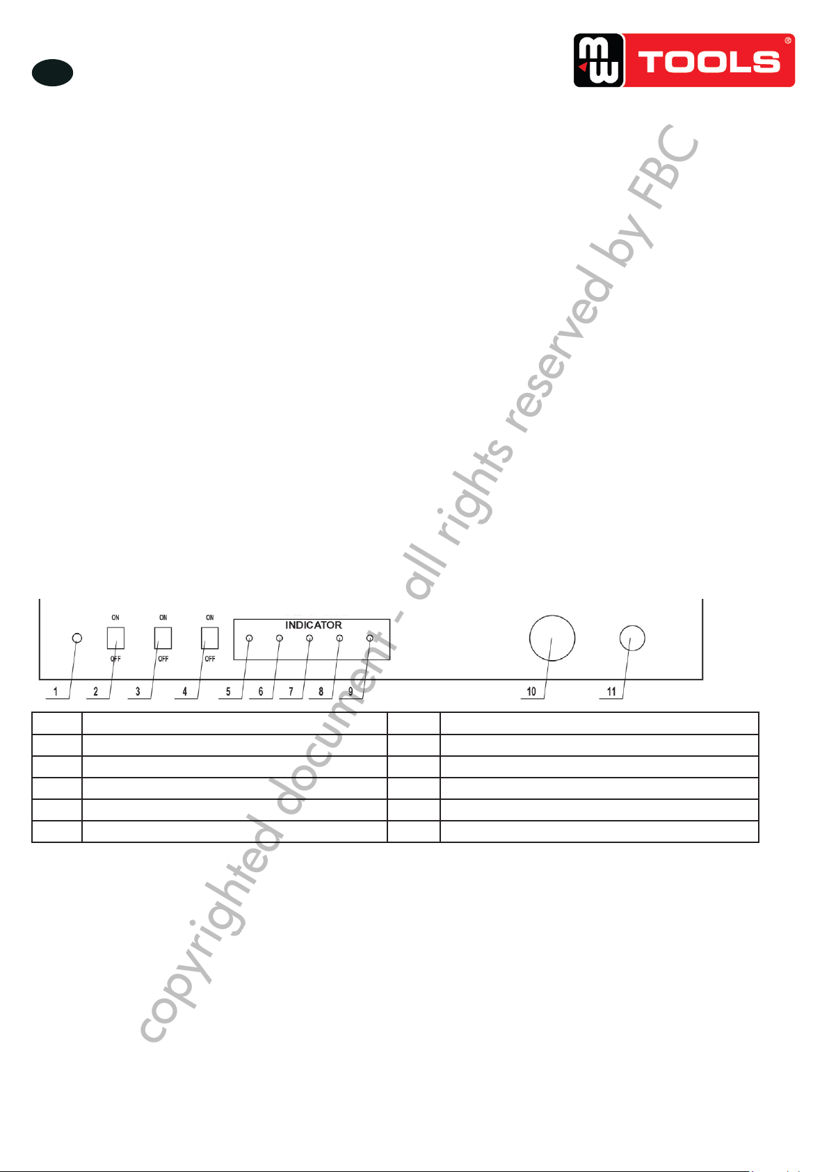
Le panneau du boîtier de commande électrique se présente comme suit :
1 Fusible 2 Témoin lumineux alimentation électrique
3Interrupteur de l’éclairage 4 Interrupteur de l’aspirateur
5 Interrupteur alimentation électrique 6 Témoin lumineux
7Témoin lumineux “portes fermées” 8Témoin lumineux pistolet xe
9Témoin lumineux pistolet mobile 10 Jauge de pression d’air
11 Valve de pression d’air
CAT415 - NLFREN - v1.0.1 - 21042017
4
NL
TOOLS
7 Instructies voor de bediening
1. Luchtspuit en spuitmond moeten in grootte overeenkomen.
2. Giet ongeveer 18 kg schuurmiddel in de trechter via de zijdeur van de cabine.
3. Plaats een lter op de ens aan de zijkant van de cabine en verbind met een stofafzuiging. Dit voorkomt dat stof de motor
binnendringt en de machine beschadigt.
4. Als de luchtdruk van de compressor 4 bar (60 Psi) bereikt, zet de schakelaar dan op “ON”. Het indicatielampje zal
beginnen branden.
5. Deze machine wordt geleverd met twee pistolen, maar met het elektrisch-pneumatisch bedieningssysteem kunnen ze niet
tegelijk gebruikt worden. Als het lampje voor het beweegbare pistool brandt, is dat beschikbaar om mee te werken. Als
het lampje voor “deuren gesloten” brandt, duw op de pedaalschakelaar en het vaste pistool zal onmiddellijk werken. Het
lampje voor het beweegbare pistool gaat dan ook uit.
6. Er is een sensor aangebracht aan de binnenkant van de deur om te controleren of de deur open of dicht is. Als het lampje
“deuren gesloten” niet brandt, zal het vaste pistool niet werken, ongeacht of de pedaalschakelaar ingedrukt wordt of niet.
7. Als de luchtdruk hoger is dan 4 bar (60 Psi) kan er een test gedaan worden. Steek de handen in de rubber handschoenen,
neem het werkstuk vast, breng het in positie onder het vaste pistool, stap op het pedaal en het straalproces begint. U kan
ook met het beweegbare pistool werken. Controleer na een tijdje het effect op het oppervlak van het werkstuk.
8. Het straalmiddel zal na het stralen op de bodem van de trechter vallen en kan opnieuw gebruikt worden.
Noot: De gebruikte lucht moet droog genoeg zijn, gebruik anders een waterlter om het water op te vangen voor het de
elektrische bediening binnengaat.
8 Verlichting en elektrisch-pneumatisch systeem
Het pneumatische systeem wordt door een elektrisch circuit bediend, dat zich in een doos op de cabine bevindt.
Zo ziet het frontpaneel van de elektrische bediening eruit:
1Zekering 2 Stroomschakelaar
3Lichtschakelaar 4 Schakelaar stofafzuiging
5 Controlelampje stroomtoevoer 6 Controlelampje
7Controlelampje “Deuren gesloten” 8 Vast pistool controlelampje
9 Beweegbaar pistool controlelampje 10 Luchtdrukmeter
11 Luchtdrukklep
copyrighted document - all rights reserved by FBC

10
M1.1.CAT415.NLFREN 14062018
FR
9 Éléments de contrôle et d’afchage
1 Fusible Protège contre la surtension et les courts-circuits
2 Interrupteur alimentation électrique Pour allumer ou éteindre l’appareil
3Interrupteur de l’éclairage Pour allumer et éteindre l’éclairage
4 Interrupteur de l’aspirateur Pour allumer ou éteindre l’aspiration de poussière
5Témoin lumineux “portes fermées” Si allumé, les portes sont fermées et vous pouvez utiliser le pistolet xe
6Témoin lumineux pistolet xe Si allumé, le pistolet xe fonctionne
7Témoin lumineux pistolet mobile Si allumé, le pistolet mobile fonctionne
8 Jauge de pression d’air Indique la pression d’air pour le sablage
9 Valve de pression d’air Pour le réglage de la pression d’air avec laquelle vous travaillez.
Tourner à droite augmente la pression, tourner à gauche la diminue.
10 Pédale de commande Pour commander le pistolet xe
11 Valve électromagnétique Pour le réglage du changement de sortie d’air
10 Utilisation du boîtier de commande électrique
1. Branchez le câble à l’arrière dans une prise de terre.
2. Mettez l’interrupteur principal sur “ON”, le témoin lumineux de l’alimentation électrique s’allume immédiatement. S’il ne
s’allume pas, contrôlez la source du courant, le câble et le fusible. S’il y a des pièces à remplacer, prenez des pièces du
même type que les pièces originales.
3. Mettez l’interrupteur de l’éclairage sur “ON”. La lumière s’allume immédiatement.
4. La sonde de contrôle pour la fermeture des porte est une pièce de sécurité pour la protection de l’opérateur et les environs
contre la matière abrasive. Si le témoin “portes fermées” est allumé, les portes sont bien fermées et le pistolet xe peut être
utilisé au moyen de la pédale de commande.
5. Si le système de commande ne fonctionne plus, faites effectuer la réparation par un technicien qualié.
11 Comment contrôler le sablage
1. Choisissez un suceur et un jet d’air de adapté au degré de nesse de la surface de la pièce de travail.
2. Utilisez une matière abrasive adaptée.
3. En sablant, bougez le pistolet et la pièce de travail de façon régulière et circulaire.
4. La pression d’air doit être stable pendant le sablage.
5. Prévoyez un bon éclairage pour une vue clair dans la cabine.
12 Entretien
1. Les tuyaux d’air ne peuvent pas être bouchés, tordus ou écrasés.
2. De la matière abrasive peut pénétrer dans le joint des portes. Après quelque temps, enlevez-la avec une brosse douce.
3. Si la visibilité dans la cabine à diminué, remplacez le lm protecteur sur le verre.
4. Quand le sablage est ni, enlevez la matière abrasive résiduelle entre le jet d’air et le suceur.
copyrighted document - all rights reserved by FBC

11
M1.1.CAT415.NLFREN 14062018
FR
13 Résolution de problèmes
Problème Cause Solution
Débit de matière abrasive diminué Matière abrasive dans le suceur 1. Matière abrasive mouillée, Séchez-la.
2. Enlevez l’eau du compresseur
La surface sablée n’est pas aussi ne
ou grosse que désiré
Matière abrasive non adaptée Remplacez par la matière abrasive adaptée
Sablage inégal Matière abrasive usée Remplacez la matière abrasive
L’éclairage ne fonctionne pas 1. Transformateur endommagé
2. Lampe endommagée
3. Mauvais contact
1. Remplacez le transformateur
2. Remplacez la lampe
3. Faites réparer par un technicien qualié
De la poussière s’échappe 1. Hublot mal fermé
2. Porte mal fermée
3. Entonnoir mal fermé
Remplacez les joints
copyrighted document - all rights reserved by FBC

12
M1.1.CAT415.NLFREN 14062018
EN
1 Introduction
The sandblast cabinet CAT415 features double side doors and an electric-pneumatic control system. With al large tightly closed
cabinet space, a transparent glass viewing window and a heavy-duty rubber glove, it’s easy and safe to operate and it really is
an ideal environment friendly product for various purposes.
The machine is delivered with two sanding guns, one connected with a xed exible metal pipe that can change direction
freely and is triggered by a pedal switch, the other, hand triggered and movable, is attached as an auxiliary gun for user’s
alternative. With an air pressure range of 4 bar - 8 bar (60 Psi - 120 Psi) to deliver abrasive materials, the machine can be
used for various surface treatment and decoration purposes, such as removing rust, paint, scale and other build-ups from metal
workpieces, or for making coarse patterns on glass.
2 Technical specications
1. Overall dimensions: 1000 x 610 x 1630 mm
2. Working area: 945 x 605 x 605 mm
3. Air pressure range: 4-8 bars (60-120 Psi)
4. Sand capacity: Approx. 18 kg
5. Abrasive materials: silica sand, glass beads, silicon carbide, emery, plastic sand, etc.
6. Power Requirement: 110 V / 60 Hz or 230 V / 50 Hz
7. Output voltage: 12 V
Contents
1 Introduction .........................................................................................................................................................12
2 Technical specications.........................................................................................................................................12
3 Assembly instructions ............................................................................................................................................13
4 Connection of air supply .......................................................................................................................................13
5 Installation of xed gun.........................................................................................................................................13
6 Installation of movable gun....................................................................................................................................13
7 Operating instructions...........................................................................................................................................14
8 Illumination and electric-pneumatic system................................................................................................................14
9 Function descriptions for controlling and indicating parts ...........................................................................................15
10 Operating instruction for the electric control box.....................................................................................................15
11 How to control the blasting effect..........................................................................................................................15
12 Maintenance .....................................................................................................................................................15
13 Troubleshooting..................................................................................................................................................16
14 Circuit diagram..................................................................................................................................................17
15 Spare parts .......................................................................................................................................................18
16 EC declaration of conformity................................................................................................................................19
copyrighted document - all rights reserved by FBC

13
M1.1.CAT415.NLFREN 14062018
EN
3 Assembly instructions
1. Remove all parts from inside cabinet including oor grate from bottom of crate, underneath cardboard.
2. Remove all parts from inside cabinet.
3. Place cabinet on its top.
4. Attach legs using four 1/4 x 1/2” bolts.
a. Front leg has name plate.
b. Rear legs will also take 2 self tapping screws
5. Put cabinet upright on legs.
6. Place foot pedal between front legs.
7. Attach doors with nuts
8. Loosen bolts on door catches and move out to full extent and tighten bolts. Moving them in slightly will tighten door seal.
9. Place glass on top of cabinet.
10. Place light xture on glass with light switch to the right. Fasten with four 1/4 x 3/4” bolts and at washers.
11. Dust collector
a. Attach body of dust collector to rear panel (right side) with 1/4 x 3/4 bolts and at washers.
b. Place top of dust collector (motor and lter) into top of unit and do up 2 catches.
c. Remove inlet box that covers the dust collector pipe inside the cabinet and place a bead of caulking around the pipe to
seal it. Put inlet box back in place.
12. Tighten all bolts, nuts and screws
13. Place oor grate with cut out corner to the front right of the cabinet. Bring hoses through opening.
14. Plug dust collector into female plug coming from light, then plug male cord from light into 115 V /60 Hz supply. Turn on
switch on vacuum, the switch on the cabinet will turn on light and vacuum or dust collector.
4 Connection of air supply
1. Take out the self-locking connector from the inner package. Wrap a sealing tape around the connector thread. Screw it into
the air inlet hole on the rear side of the electric control box and tighten.
2. Push the coupler of the self-locking connector toward the air inlet hole, the cone-shaped end of the connector will
immediately pop out. Fit it into the air hose connecting to the air compressor. Fasten with a clamp. Push the coupler again
and t in the opposite side of the cone-shaped end. Release and the connection is secured.
5 Installation of xed gun
1. Remove the suction head from the xed gun. Fit in an air jet. Reconnect the suction head and tighten. Loosen the M6 screw
on the gun side and install the corresponding nozzle. Tighten the screw.
2. Connect the side branch of the gun with a suction hose and connect the rear inlet of the gun to the exible metal pipe in
the cabinet. Screw until secured.
3. Connect the other end of the suction hose tot corresponding suction pipe.
6 Installation of movable gun
1. Connect one end of the high pressure air hose to the air connector on the right side of the electric control box, the other
end to the air inlet of the movable gun. Tighten with clamps.
2. Connect one end of the suction hose tot de side branch of the movable gun, the other end to the xed suction pipe.
3. Installation of air jet and nozzle are the same as for the xed gun.
4. Put the movable gun on the mesh screen
copyrighted document - all rights reserved by FBC

14
M1.1.CAT415.NLFREN 14062018
EN
7 Operating instructions
1. The air jet and the nozzle should match each other in size
2. Pour abrasive material approx. 18 kg into the funnel through the side door of the cabinet.
3. Cover a lter on the ange on the rear side of the cabinet and connect with a dust collector. This can prevent dust from
entering the motor and causing damage to the machine.
4. When the air pressure form the compressor reaches 4 bar (60 Psi), put the power switch to “ON”. The power indicator
lights up.
5. This machine is delivered with two sanding guns, but under the control of the electric-pneumatic system only one of them at
a time is available for working. When the movable gun indicator is on, the movable gun is available for working. While
the door-closed indicator is on, step on the pedal switch and the xed gun will immediately start to blast. At the same time,
the movable gun indicator will turn off.
6. There is a tester inside the doors to check whether they are open or closed. If the door-closed indicator is not on, the control
system is in a protecting mode and the xed gun will not work, no matter if the pedal switch is pushed or not.
7. When the air pressure exceeds 4 bar (60 Psi), you can start a test blast. Insert hands into the gloves, grasp the workpiece,
position it under the xed gun and step on the pedal switch to start the blasting process. You can also use the movable
gun. Check the blasted surface to see the effect after a while.
8. The abrasive material will drop to the bottom of the funnel after blasting and can be recycled.
Note: The high pressure air should be dry. If it contains too much moisture, attach a water lter to separate moisture before the
air enters the electric control box.
8 Illumination and electric-pneumatic system
The pneumatic system is controlled by an electric circuit, which is set inside a box on top of the cabinet.
Layout of the front panel of the electric control box:
1Fuse 2Power switch
3Light switch 4 Dust switch
5 Power indicator 6 Control indicator
7 Door-closed indicator 8 Fixed gun indicator
9 Movable gun indicator 10 Air pressure gauge
11 Air pressure valve
CAT415 - NLFREN - v1.0.1 - 21042017
4
NL
TOOLS
7 Instructies voor de bediening
1. Luchtspuit en spuitmond moeten in grootte overeenkomen.
2. Giet ongeveer 18 kg schuurmiddel in de trechter via de zijdeur van de cabine.
3. Plaats een lter op de ens aan de zijkant van de cabine en verbind met een stofafzuiging. Dit voorkomt dat stof de motor
binnendringt en de machine beschadigt.
4. Als de luchtdruk van de compressor 4 bar (60 Psi) bereikt, zet de schakelaar dan op “ON”. Het indicatielampje zal
beginnen branden.
5. Deze machine wordt geleverd met twee pistolen, maar met het elektrisch-pneumatisch bedieningssysteem kunnen ze niet
tegelijk gebruikt worden. Als het lampje voor het beweegbare pistool brandt, is dat beschikbaar om mee te werken. Als
het lampje voor “deuren gesloten” brandt, duw op de pedaalschakelaar en het vaste pistool zal onmiddellijk werken. Het
lampje voor het beweegbare pistool gaat dan ook uit.
6. Er is een sensor aangebracht aan de binnenkant van de deur om te controleren of de deur open of dicht is. Als het lampje
“deuren gesloten” niet brandt, zal het vaste pistool niet werken, ongeacht of de pedaalschakelaar ingedrukt wordt of niet.
7. Als de luchtdruk hoger is dan 4 bar (60 Psi) kan er een test gedaan worden. Steek de handen in de rubber handschoenen,
neem het werkstuk vast, breng het in positie onder het vaste pistool, stap op het pedaal en het straalproces begint. U kan
ook met het beweegbare pistool werken. Controleer na een tijdje het effect op het oppervlak van het werkstuk.
8. Het straalmiddel zal na het stralen op de bodem van de trechter vallen en kan opnieuw gebruikt worden.
Noot: De gebruikte lucht moet droog genoeg zijn, gebruik anders een waterlter om het water op te vangen voor het de
elektrische bediening binnengaat.
8 Verlichting en elektrisch-pneumatisch systeem
Het pneumatische systeem wordt door een elektrisch circuit bediend, dat zich in een doos op de cabine bevindt.
Zo ziet het frontpaneel van de elektrische bediening eruit:
1Zekering 2 Stroomschakelaar
3Lichtschakelaar 4 Schakelaar stofafzuiging
5 Controlelampje stroomtoevoer 6 Controlelampje
7Controlelampje “Deuren gesloten” 8 Vast pistool controlelampje
9 Beweegbaar pistool controlelampje 10 Luchtdrukmeter
11 Luchtdrukklep
copyrighted document - all rights reserved by FBC

15
M1.1.CAT415.NLFREN 14062018
EN
9 Function descriptions for controlling and indicating parts
1Fuse Safety feature for overload and short circuit protection
2Power switch To connect or disconnect power source
3Light switch To turn of or on light
4 Power indicator If lit, power source is connected
5 Door-closed indicator if lit, doors are closed and xed gun is available for working
6Fixed gun indicator if lit, xed gun is blasting
7 movable gun indicator if lit, movable gun is ready for working or is blasting
8 air pressure gauge Indicates air pressure for blasting
9 Air pressure valve Controls the working pressure of compressed air, turn clockwise
to increase, turn counterclockwise to decrease
10 Pedal switch Controls the blasting time of the xed gun
11 Electromagnetic valve Controls the shift of air outlet
10 Operating instruction for the electric control box
1. Connect the power cord on the rear panel to a grounded power source.
2. Press the power switch to “on”, the power indicator will immediately light up. If not, check the power source and the cord
and see if the fuse is broken. Should any part be replaced, use one of the same type.
3. Press the light switch to “on”, the light will immediately be on.
4. The door status tester is a safety feature designed to protect the operator and surrounding environment from the abrasive
material. When the door-closed indicator is on, it indicates that the door is closed securely and the xed gun is available
for working, controlled by the pedal switch.
5. If the control system breaks down or if there is any malfunction, have it repaired by a qualied technician.
11 How to control the blasting effect
1. Choose a nozzle and air jet of suitable size according to the desired grade of neness or coarseness of the surface of the
workpiece.
2. Use a suitable grade of abrasive. And because it wears during the blasting process, a double layer of ordinary window
screen is recommended to strain the abrasive after some time of use.
3. When blasting, move the gun or workpiece evenly an circularly.
4. The air pressure should be stable when blasting.
5. Ensure a good illumination to have a clear view of the cabinet space.
12 Maintenance
1. The air hoses should not be blocked, twisted or crushed by force.
2. Abrasive particles may work their way into the door liner. Use a soft brush to clean after some time of use.
3. If visibility of the cabinet is reduced, replace the protecting lm on the organic glass.
4. When blasting is nished, clean the passage from air jet to nozzle. Make sure no abrasive material is left.
copyrighted document - all rights reserved by FBC

16
M1.1.CAT415.NLFREN 14062018
EN
13 Troubleshooting
Problem Cause Solution
Abrasive ow decreasing Abrasive build-up in the nozzle 1. Wet abrasive, have it dried
2. Drain water from the air
compressor
The blasted surface is not as coarse or
as ne as intended Wrong grade of abrasive material Replace by abrasive material of right
grade
Uneven blasting Abrasive material worn Strain or replace abrasive material
Light failure 1. Transformer damaged
2. Light damaged
3. Bad contact
1. Replace transformer
2. Replace light
3. Have it repaired by a qualied
technician
Dust leakage 1. Viewing window not sealed
properly
2. Door not sealed properly
3. Funnel not sealed properly
Replace corresponding foam sealing
strip.
copyrighted document - all rights reserved by FBC

17
M1.1.CAT415.NLFREN 14062018
NL
FR
EN
14 Elektrisch schema
14 Schéma électrique
14 Circuit diagram
17
CAT415 - NLFREN - v1.0.1 - 21042017
TOOLS
NL
FR
EN
14 Elektrisch schema
14 Schéma électrique
14 Circuit diagram
copyrighted document - all rights reserved by FBC

18
M1.1.CAT415.NLFREN 14062018
NL
FR
EN
15 Onderdelen
15 Pièces détachées
15 Spare parts
18
CAT415 - NLFREN - v1.0.1 - 21042017
TOOLS
NL
FR
EN
15 Onderdelen
15 Pièces détachées
15 Spare parts
copyrighted document - all rights reserved by FBC

19
M1.1.CAT415.NLFREN 14062018
Fabrikant/Invoerder
Fabricant/Importateur
Manufacturer/Retailer
Verklaart hierbij dat het volgende product :
Déclare par la présente que le produit suivant :
Hereby declares that the following product :
Product
Produit
Product
Zandstraalcabine
Cabine de sablage
Sandblast cabinet
Order nr. :
Geldende CE-richtlijnen
Normes CE en vigueur
Relevant EU directives
2006/42/EC
2014/30/EU
EN61000-6-1:2007
EN61000-6-3:2007+A12011
Overeenstemt met de bestemming van de hierboven aangeduide richtlijnen - met inbegrip van deze betreffende
het tijdstip van de verklaring der geldende veranderingen.
Répond aux normes générales caractérisées plus haut, y compris celles dont la date correspond aux
modications en vigueur.
Meets the provisions of the aforementioned directive, including, any amendments valid at the time of this
statement.
Vynckier Tools sa
Avenue Patrick Wagnon, 7
ZAEM de Haureu
B-7700 Mouscron
16 EG conformiteitsverklaring
16 Déclaration de conformité CE
16 EC declaration of conformity
CAT415 (754751444)
FR
EN
NL
Bart Vynckier, Director
VYNCKIER TOOLS sa
Mouscron, 14/06/2018
copyrighted document - all rights reserved by FBC
This manual suits for next models
1
Table of contents
Languages:
Other MW TOOLS Power Tools manuals

MW TOOLS
MW TOOLS CATOMA 20S User manual

MW TOOLS
MW TOOLS CAT02010 User manual

MW TOOLS
MW TOOLS PH15BT User manual

MW TOOLS
MW TOOLS PPH75B User manual

MW TOOLS
MW TOOLS CATOMA 30S User manual

MW TOOLS
MW TOOLS CAT420 User manual

MW TOOLS
MW TOOLS CAT8301OTS User manual

MW TOOLS
MW TOOLS CAT880 User manual

MW TOOLS
MW TOOLS PPH20B User manual

MW TOOLS
MW TOOLS CAT990 User manual