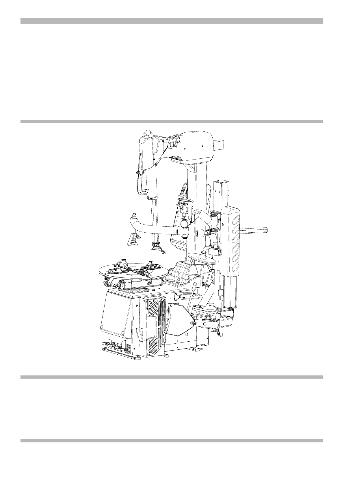
Snap-On EEWH337A User manual

OPERATION INSTRUCTIONS
Air-Electric tilt back tower tire changers for passenger car, light commercial vehicle
and motorcycle tires designed for one-piece rims. Dimensions based on OEM tires
and wheels only. This tire changer is designed for ease of operation, safe handling of
rims, reliability and speed.
AIR/ELECTRIC TIRE CHANGER
EEWH337A

Snap-on EEWH337A
ii EN
SAFETY INFORMATION
For your safety, read this manual thoroughly
before operating the Tire Changer
This tire changer is intended for use by properly trained automotive technicians. The safety mes-
sages presented in this section and throughout the manual are reminders to the operator to exer-
cise extreme caution when servicing tires with these products.
There are many variations in procedures, techniques, tools, and parts for mounting and demoun-
ting of tires, as well as the skill of the individual doing the work. Because of the vast number of
wheel and tire applications and potential uses of the product, the manufacturer cannot possibly
anticipate or provide advice or safety messages to cover every situation. It is the automotive tech-
nician’s responsibility to be knowledgeable of the wheels and tires being serviced. It is essential
to use proper service methods in an appropriate and acceptable manner that does not endanger
your safety, the safety of others in the work area or the equipment or vehicle being serviced.
It is assumed that, prior to using that tire changer, the operator has a thorough understanding of
the wheels and tires being serviced. In addition, it is assumed he has a thorough knowledge of
the operation and safety features of the rack, lift, or •oor jack being utilized, and has the proper
hand and power tools necessary to service the vehicle in a safe manner.
Before using the present tire changer, always refer to and follow the safety messages and service
procedures provided by the manufacturers of the equipment being used and the vehicle being
serviced.
IMPORTANT !! SAVE THESE INSTRUCTIONS - DO NOT DISCARD !!

Snap-on EEWH337A
EN iii
IMPORTANT SAFETY INSTRUCTIONS
When using this equipment, basic safety precautions should always be followed,
including the following:
1. Read all instructions.
2. Do not operate equipment with a damaged power cord or if the equipment has been
damaged - until it has been examined by a quali•ed authorized service technician.
3. If an extension cord is used, a cord with a current rating equal to or more than that
of the machine should be used. Cords rated for less current than the equipment may
overheat. Care should be taken to arrange the cord so that it will not be tripped over
or pulled.
4. Always unplug equipment from electrical outlet when not in use. Never use the cord
to pull the plug from the outlet. Grasp plug and pull to disconnect.
5. To reduce the risk of •re, do not operate equipment in the vicinity of open contai-
ners of •ammable liquids (gasoline).
6. Keep hair, loose •tting clothing, •ngers and all parts of the body away from moving
parts.
7. Adequate ventilation should be provided when working on operating internal com-
bustion engines.
8. To reduce the risk of electric shock, do not use on wet surfaces or expose to rain.
9. Do not hammer any part of the machine, it isn’t designed to be an anvil.
10. Do not allow unauthorized personnel to operate the equipment.
11. Do not disable or bypass the safety systems and follow all the safety procedures.
12.
Use only as described in this manual. Use only manufacturer’s recommended attachments.
13. Always securely lock the rim before actuating rotation.
14. ALWAYS WEAR SAFETY GLASSES. Everyday eyeglasses only have impact resi-
stant lenses, they are NOT safety glasses.
15. The equipment is for indoor use only.
SAVE THESE INSTRUCTIONS

CSA C22.2 Standards complying
. Accessories guide.
May 2021
Release:______ A ______
Page 5
Page 7
Page 7
Page 7
Page 8
Page 8
Page 8
Page 8
Page 9
Page 9
Page 10
Page 13
Page 15
Page 15
Page 17
Page 18
Page 18
Page 19
Page 20
Page 21
Page 21
Page 21
Page 22
Page 23
Page 23
Page 23
Page 24
Page 25
Page 27
UPDATING GUIDE
Snap-on EEWH337A
iv EN
TABLE OF CONTENTS
Safety Lables
1.0 Introduction
1.1 Nomenclature
1.2 Speci!cations
1.3 Accessories and Consumables
1.4 Dimentions Of The Machine
1.5 General Cautions
1.5.1 Precautions
2.0 Accessories Installation
2.1 Installing the Sliding jaw +4 inch kit
2.2 Rapid change-over kit for +4 inch extension
3.0 Controls
4.0 Mounting And Demounting-Precautions
4.1 Demounting Tubeless Tires
4.1.1 Use the bead presser as a Demounting Device
4.2 Mounting Tubeless Tires
4.2.1 Use the bead presser as a Mounting Help device
4.3 Beading the Tires
4.4 Mounting And Demounting Motorcycle Tires
5.0 Demounting Tube-Type Tires
5.1 Mounting Tube-Type Tires
5.2 In"ating Tube-Type Tires
6.0 Maintenance
7.0 Disposing of the unit
7.1 Disposal Informations
i Installation requirements
ii Carriage – Uncrating - Moving the machines
iii Installation procedures
WARRANTY/SERVICE AND REPAIR

Snap-on EEWH337A
EN 5
INSTRUCTIONS: Safety Label Meanings
IMPORTANT!! SAVE THESE INSTRUCTIONS
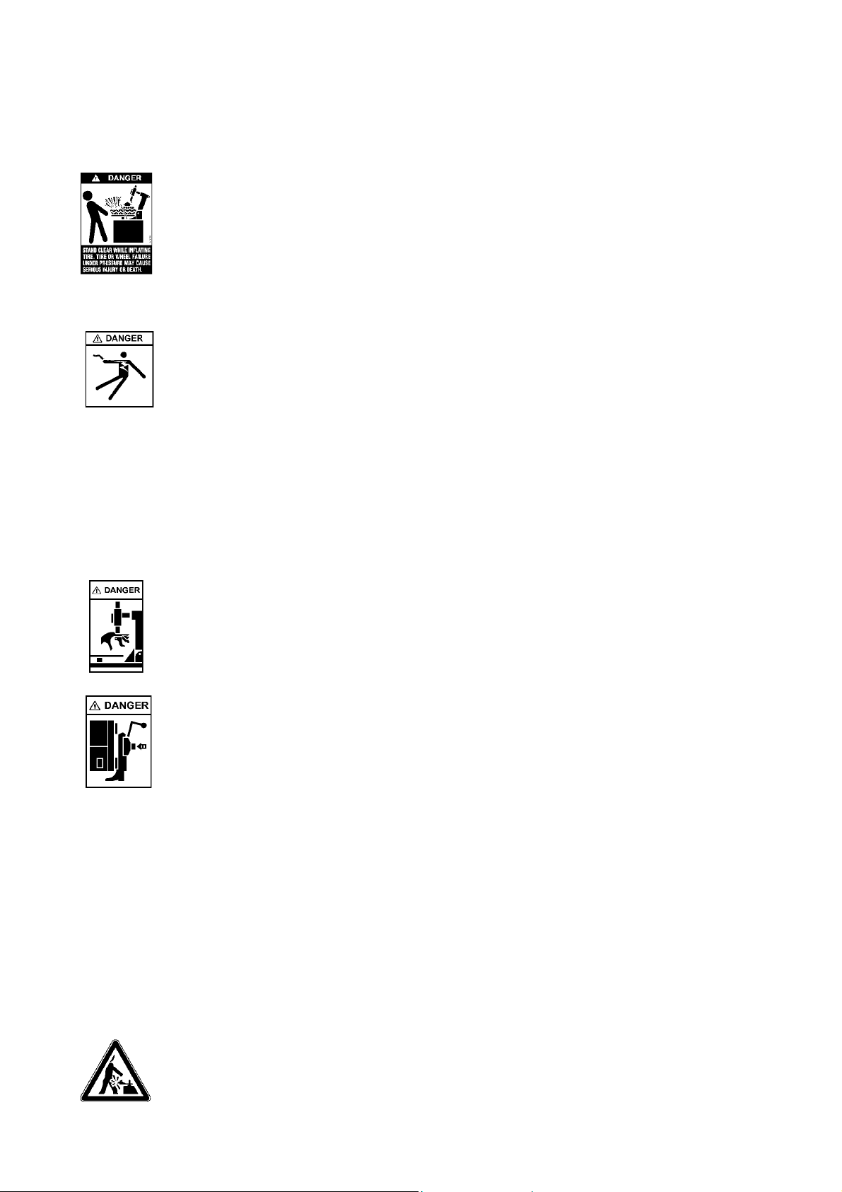
Overinflated tires or tires mounted on the wrong sized rims can explode producing hazardous fl
ying debris.
· Read and understand the operation instructions before using this tire changer.
· Never mount tire on rim with di"erent sized diameter.
· Never exceed maximum in#ation pressure listed on tire sidewall.
· Always use safety restraint arm to hold wheel in place while in#ating.
· Always use attached air hose to in#ate tires.
Exploding tires can cause death or serious injury.
Risk of electrical shock.
· Do not operate equipment with a damaged power cord or if the equipment has been dropped or damaged,
until it has been examined by a quali$ed service person.
· If an extension cord is necessary, a cord with a current rating equal to or greater than that of the equipment
should be used. Cords rated for less current than the equipment can overheat.
· Unplug equipment from electrical outlet when not in use. Never use the cord to pull the plug from the outlet.
Grasp plug and pull to disconnect.
· Do not expose the equipment to rain. Do not use on wet surfaces.
· Plug unit into correct power supply.
· Do not remove or bypass grounding pin.
Contact with high voltages can cause death or serious injury.
Risk of electrical shock. High voltages are present within the unit.
· There are no user serviceable items within the unit.
· Service on the unit must be performed by quali$ed personnel.
· Do not open any part of the unit other than noted and allowed areas.
· Turn power switch o" and unplug the unit before servicing.
Contact with high voltages can cause death or serious injury.
Risk of crushing.
· Become familiar with all controls before proceeding with operation.
· Stand away from the bead breaker arm when in operation.
· Apply air to breaker in bursts if necessary to control arm depth.
· Don’t allow to approach extraneous people to the service.
Contact with moving parts could cause injury.
Risk of pinching or crushing hands and fingers.
· Keep hands and $ngers clear of rim edge during demounting and mounting process.
· Keep hands and $ngers clear of mount/demount head during operation.
· Keep hands and other body parts away from moving surfaces.
· Do not use tools other than those supplied with tire changer.
· Do not use unapproved accessories
· Do not bypass any safety features.
· Use proper tire lubricant to prevent tire binding.
Contact with moving parts could cause injury.
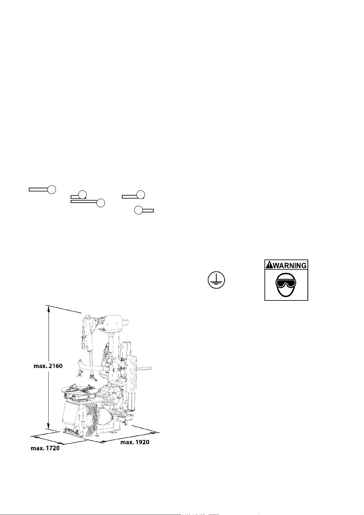
Risk of eye injury. Debris, dirt, and fluids may drop from wheels.
· Remove any debris from tire tread and wheel surfaces.
· Remove excess tire lubricant before in#ating.
· Knock o" any loose debris. Clean surfaces as needed to avoid any materials from falling.
· Wear approved safety glasses during mount and demount procedures.
Debris, dirt, and fluids projection can cause serious eye injury.
Risk of injury. Tools may break or slip if improperly used or maintained.
· Use the correct tool for the task.
· Frequently inspect, clean, and lubricate (if recommended) all tools.
· Follow recommended procedures when performing wheel services.
Tools that break or slip can cause injury.
Collision and dragging hazard:
· do not rotate the turntable without wheel on board
· do not approach the turntable plate while it is moving
· pay attention to the jaws when these stick out of the turntable plate
· do not place any protruding objects on the turntable plate
· do not place any protruding objects near the turntable plate
Contact with moving parts could cause injury.

Snap-on EEWH337A
6EN
Tires and Rims that are not the same diameter are mismatched.
· NEVER attempt to mount or inflate any tire and rim that are mismatched.
· ALWAYS check to see that tire and rim diameters are the same.
A mismatched tire and rim will explode causing death or serious personal injury
Over-pressurized tires can explode causing flying debris.
· Read and understand Operator’s Manual before operating.
· Keep bystanders away from work area.
· ALWAYS wear Safety Goggles.
· ALWAYS check to see that Tire and Rim diameters are the same.
· NEVER attempt to mount or inflate any Tire and Rim with different diameters.
· Inspect tires, NEVER inflate tires that are damaged, rotten or worn.
· NEVER inflate ‘Split Rim Wheels’ on this tire changer, remove them and use only an approved
safety inflation cage designed for this purpose.
· Lock turntable Clamp on inside of rim before attempting to inflate tire.
· Use approved tire bead lubricant before removing or installing tire on rim.
· ALWAYS position the “Safety Restraint Arm” (optional) over the wheel to hold it to the turntable
while inflating if so equipped.
· If a tire explodes on this tire changer, STOP using it until the “Safety Restraint Arm” has
been replaced, which must be done even if no damage is seen.
· NEVER place head or body over a tire during inflation process.
· Use short bursts of air to seat tire beads, check tire air pressure frequently.
· NEVER exceed tire manufacturer’s pressure limits.
· NEVER attempt to bypass or alter the built in air pressure limiter. Only inflate tire with air
hose supplied with tire changer. NEVER use shop inflation hose to inflate a tire.
· Tire Changer must be properly anchored to concrete floor.
Exploding Tires can cause serious injury.

1-1
1
19 18
17
16
2
4
315
22
5
6
8
7
9
11 10
13
14 12
20
21
{
23
Snap-on EEWH337A
925 lbs (420 Kg)
psi 110-170 (8-12 bar)
lbs 3300 (15 kN)
230 V, 1 ph, 50/60 Hz,16A
kW 0.9 (Hp 1,2)
lbf·ft 738 (Nm 1000)
7-14 rpm
44” (mm 1120)
17” (mm 430)
12”-26”
14”-26”
10”-25”
<70 dBA
120dBA
EN 7
1.0 Introduction
Congratulations on purchasing the
“EEWH337A”
electric/
air tire changer.
This tire changer is designed for ease of operation, safe
handling of rims, reliability and speed.
This combination of features means more pro!t and
added versatility for your shop, enabling you to work with
aluminium or magnesium alloy wheels without damaging
customer’s rims.
With a minimum of maintenance and care your tire
changer will provide many years of trouble-free operation.
Please read this manual thoroughly before operating the
unit. Instructions on use, maintenance and operational
requirements of the machine are covered in this manual.
STORE THIS MANUAL IN A SAFE PLACE FOR
FUTURE REFERENCE. READ THIS MANUAL
THOROUGHLY BEFORE USING THE MACHINE.
1.1 Nomenclature
Before installing and using the electric/air tire changer it is
suggested that you become familiar with the nomenclature
of the machine’s components (Fig. 1-1).
1.2 Specifications
Electric-air tire changer for car, light commercial vehicle
and motorcycle tires designed for one-piece rims.
Weight
Air pressure required
Bead breaker force
Electric specifi
cations:
Motor power
Max. torque
Turntable rotation speed:
Max. wheel diameter
Max. wheel width
Rim diam. outside locking
Rim diam. inside locking
Motorcycle wheels adapters (optional)
Acoustic pressure:
Acoustic pressure - bead seater
1 Vertical slide
2 Mounting arm, horizontally displaceable
3 Lever with push-button
4 Handle
5 Mount/demount head
6 Tower or column
7 Turntable
8 multi-position Jaw
9 Bead breaker arm
10 Bead breaker blade
11 Bead breaker pads
12 Lube Pail
13 Foot pedal controls
14 Bead seater/in"ator pedal
15 In"ation gauge
16 Air jets
17 Top bead roller
18 Bead assist arm
19 Rise/fall control lever
20 Bead depressor arm
21 Bead depressor tool
22 Bottom bead roller
23 ON-OFF functionality
When the unit does not have a power switch on and o#,
disconnect and reconnect the power plug.
CAUTION: WE RECOMMEND SWITCHING OFF THE
UNIT AT THE END OF EACH WORKING DAY.

1-3
1-2
B
2 3
45
1
D
Snap-on EEWH337A
8EN
1.3 Accessories and consumables
A series of accessories are usually available for the
machine. All accessories are indicated on the website:
http://service.snapon-equipment.net/
After accessing the website, proceed as follows:
Fig. 1-2
·Select Accessory Plan (1).
·Select the reference brand in the !eld Brands (2).
·Select the Type of product “Tyre changers” in the !eld
Product lines (3).
·Open the field Model (4) and select the specific
machine model among the ones in the list.
·Enter “SEARCH” (5) to display the list of available
accessories.
NOTE: Use the codes in the list for the purchase
orders.
1.4 Dimensions of the Machine
Fig.1-3
Dimensions expressed in mm.
1.5 General Cautions
A. DURING USE AND MAINTENANCE OF THE MACHINE
IT IS MANDATORY TO COMPLY WITH ALL LAWS AND
REGULATIONS FOR ACCIDENT PREVENTION.
B. THE ELECTRICAL POWER SOURCE MUST HAVE A
GROUND CABLE AND THE GROUND CABLE OF THE
MACHINE (YELLOW WITH GREEN) MUST BE CONNECTED
TO THE GROUND CABLE OF THE POWER SOURCE (B).
C. BEFORE PERFORMING ANY MAINTENANCE OR
REPAIRS THE MACHINE MUST BE DISCONNECTED FROM
THE AIR AND ELECTRIC SUPPLY.
D. NEVER WEAR TIES, CHAINS OR OTHER LOOSE
ARTICLES WHEN USING, MAINTAINING OR REPAIRING
THE MACHINE. LONG HAIR IS ALSO DANGEROUS AND
SHOULD BE KEPT UNDER A HAT.
THE USER MUST WEAR PROPER SAFETY ATTIRE I.E.:
GLOVES, SAFETY SHOES AND GLASSES (D).
E. MAINTAIN ALL ELECTRIC CORDS IN GOOD REPAIR.
F. KEEP SAFETY FEATURES IN PLACE AND IN WORKING
ORDER.
G. KEEP WORKING AREA CLEAN. CLUTTERED AREAS
INVITE ACCIDENTS.
H. AVOID DANGEROUS ENVIRONMENTS. DON’T USE
POWER TOOLS OR ELECTRICAL EQUIPMENT IN DAMP OR
WET LOCATIONS, OR EXPOSE THEM TO RAIN.
J. KEEP THE WORK AREA WELL LIGHTED.
1.5.1 Precautions
ANY MISUSE OR MODIFICATION OF THIS DEVICE OR OF ITS
PARTS OR COMPONENTS NOT PREVIOUSLY AUTHORIZED
BY THE MANUFACTURER WAIVE THE MANUFACTURER
FROM ANY DAMAGE CONSEQUENT OR RELATED TO THE
ABOVE MENTIONED MISUSES.
REMOVING OR BYPASSING SAFETY DEVICES OR
WARNING LABELS OF THE MACHINE IS A VIOLATION OF
THE SAFETY REGULATIONS.
THE USE OF THIS DEVICE IS ALLOWED ONLY IN
LOCATIONS WITH NO EXPLOSION OR FIRE HAZARD.
THIS EQUIPMENT IS DESIGNED TO RECEIVE ORIGINAL
SPARE PARTS AND ACCESSORIES ONLY.
THE INSTALLATION SHALL BE CARRIED OUT ONLY BY
QUALIFIED PERSONNEL AND WITHIN THE SCOPE OF THE
INSTRUCTIONS PROVIDED IN THIS MANUAL.
IN CASE A DEFECTIVE FUNCTIONING CONDITION IS
DETECTED, STOP USING THE MACHINE AND CALL 800-
225-5786 FOR SERVICE.

2-1
2-2
A
B
R
C
D
E
Snap-on EEWH337A
EN 9
2.0 Accessories Installation
2.1 Installing the OPTIONAL KIT:
EAA0331G91A - Sliding jaw +4 inch kit
WARNING
BEFORE INSTALLATION, DI SCONNECT THE
ELECTRICAL AND AIR SUPPLY FROM THE TIRE
CHANGER.
See Figure 2-1
1) Remove the standard jaws (R), present on the tire
changer turntable.
2) Insert the +4” jaws supplied in the kit on the turntable
sliding parts and align the side holes (A) with the holes
(B) in the sliding parts.
CAUTION: SECURE THE SLIDING PARTS WITH BOTH
SCREWS IN THE HOLES PREPARED.
See Figure 2-2
3) Insert the screws (C) in the side holes in the jaws, put
the washers (D) on the opposite side and secure with
the nuts (E).
NOTE: If the holes (B) in the sliding parts are blocked by
dirt, clean them by MANUALLY inserting an 8 mm diameter
spiral bit in them several times.
CAUTION: AFTER INSTALLATION, THE JAWS MUST
BE EQUIDISTANT FROM THE CENTER OF THE
TURNTABLE.

2-3
2-4
E
D
C
F
H
G
Snap-on EEWH337A
10 EN
2.2 Installing the OPTIONAL KIT:
EAA0304G80A -
Rapid change-over kit for mount
dismount head with +4 inch extension
WARNING
BEFORE INSTALLATION , DISCON NECT THE
ELECTRICAL AND AIR SUPPLY FROM THE TIRE
CHANGER.
Preliminary operations
See Figure 2-3
1) Remove the two screws (A) from the mount dismount
head !tted on the tire changer.
2) Unscrew and remove the retaining screw (B) underneath
the M/D head.
3) The hexagonal rod will have to be held back by hand
to prevent the vertical spring from pushing it out upwards.
Remove it from the hexagonal rod.
Installing the Kit
See Figure 2-4
4) Insert the threaded ring nut (C), the washer 41x53x2
(D) and place the connection bush (E) on the hexagonal
rod, positioned so that the holes for the adjuster screws
are facing upward and in line with the holes in the rod.
5) Screw in the screw 10x20 (G) by hand, without
tightening, also !tting the washer 10x32 (H).
6) Screw in the two screws (F) supplied in the kit by the
same amount, without tightening, so that the bushing
remains centred.
7) Tighten the screws (F) fully, tightening them by small
amounts in turn, then to conclude tighten the screw
underneath (G).

2-6
2-5
P
M
RS
N
Q
L
Snap-on EEWH337A
EN 11
Installing the offset mount dismount head
supplied in the Kit
See Figure 2-5
8) Fit the M/D head supplied in the Kit (L) on the snap
connection for the extension, positioned so that the
adjuster screws (M) are in line with the seats (N) on the
hub of the connection.
9) Screw in the screws (M) on the M/D head by the same
amount, without tightening fully.
10) Screw in the screw 10x30 (S) with the washer 10x38
(R) by hand, without tightening fully.
11) Fit the assembly formed as described onto the bushing
previously !tted. Tighten the ring nut with the wrench
supplied in the kit (Q).
N.B.: Place the mount dismount head in the same position
as the original removed from the tire changer.
Adjusting the mount dismount head:
See Figure 2-6
After the mount dismount head has been !tted on the
snap connection, it must be adjusted by means of the two
screws (M) to position the mount dismount head correctly
in relation to the wheels on which it is to work.
12) Connect the tire changer to the electricity and
compressed air supplies.
13) Clamp a new rim or a rim in good condition with 20”
diameter on the turntable.
14) Loosen the two screws (M) and the screw underneath
so that the M/D head is not rigidly locked in place but can
turn through a small sector relative to the support hub (P).
15) Move the M/D head towards the edge of the rim, as
for normal operation, then lock it in position.
16) Tighten one of the two adjuster screws until the inside
of the claw of the M/D head is about 1/25” (1 mm) from
the edge of the rim, as indicated by point (X) and on the
opposite side of the M/D head the edge of the M/D head is
aligned with the edge of the rim, as indicated by point (Y).
17) Tighten both screws, keeping the M/D head in this
position. Move the M/D head away from the edge of the
rim, then tighten the screw (S Fig. 2.0-5) under the mount
dismount head fully home, with a torque of 35 Nm.

2-7
2-8
P2
M
R
S
2/3”
(17mm)
1/25”
(1mm)
20”
Snap-on EEWH337A
12 EN
Installing and Adjusting the original tire
changer mount dismount head
See Figure 2-7
18) Fix the mount dismount head previously removed from
the tire changer onto the second snap connection (P2)
supplied with the kit. Repeat the installation operations
in points 8 to 11 of these instructions.
19) Adjust as already described in points 14 and 15.
20) Tighten one of the two adjuster screws until the inside
of the claw of the mount dismount head is about 1/25” (1
mm) from the edge of the rim, and at the same time, the
edge of the mount dismount head is flush with the edge of
the rim on the opposite side of the mount dismount head
in the point shown in the diagram (Y Fig. 2-8).
21) Complete the adjustment by proceeding as indicated
in point 17.
22) Remove the rim from the turntable.
The kit is now ready for use.
You can use the standard mount dismount head for
conventional rims or, if you need to handle rims with a
diameter greater than the tire changer’s rated capacity,
rapidly substitute it with the mount dismount head with
the +4 inch extension.
The offset mount dismount head is also useful by offering
additional tire clearance when removing and installing the
bottom bead of the tire.
Mount dismount head change-over is extremely fast,
allowing you to work on rims with a diameter up to four
inches larger than the maximum permitted on your tire
changer.

3-1
3-2
AB
C
Snap-on EEWH337A
EN 13
3.0 Controls
Before operating the machine, ensure that you have well
understood the operation and function of all the controls
(Fig.3-1).
A. Press down and release, WITH LEFT FOOT, the first
pedal from the left: the column tilts backwards.
Do it again: the column tilts forward.
WARNING: DANGER OF BODY CRUSHING
TO MINIMIZE THE RISK OF SCRATCHING ALLOY
RIMS, THESE SHOULD BE CLAMPED FROM THE
OUTSIDE. ALSO, SOME STEEL WHEELS ARE
TAPERED AND THEREFORE WILL NEED TO BE
CLAMPED FROM THE OUTSIDE AS WELL.
B. Press down and release, WITH LEFT FOOT, the
second pedal from the left: the clamps of the turntable will
retract. Do it again: the clamps will expand. If you press
the pedal prior to the end of the stroke and release, the
clamps may be stopped in any position.
WARNING: WATCH YOUR FINGERS AND LEGS!
C. Press down and hold, WITH RIGHT FOOT, the first
pedal from the right: the turntable turns clockwise.
1.
3/4 down approximately, the turntable rotates at the
minimum speed. The torque is maximum in this condition.
2. All the way down the turntable rotates at the
maximum speed (only for 220V).
Lift the pedal and the turntable turns counter-clockwise.
D. Open the bead breaker arm. Press down and hold,
WITH LEFT FOOT, the second pedal from the right: by
doing this you operate the bead breaker blade and the
arm will move towards the machine. Release the pedal:
the bead breaker blade will retract.
E. The push button on the handle allows to release the
arms and position the mount/demount head in the correct
position.
1. To unlock and let the slide with the head go up: push
the button firmly with the forefinger, in the direction of
the arrow (AFig. 3-2).
2. To unlock and let the slide with the head go down:
push the button with the thumb in the direction of the
arrow, until the resistance increases (BFig. 3-2).
3. To lock: push the button firmly with the thumb (C
Fig. 3-2).
ATTENTION! DANGER OF HAND CRUSHING

3-3
3-4
2
31 2
Snap-on EEWH337A
14 EN
F.
Press bead seater/inflator pedal on left side of the machine
down (1, Fig. 3-3): air will come from inflation hose end.
Only for Tubeless wheel models:
F1. Press bead seater/inflator pedal (1, Fig. 3-3) on left
side of the machine half way down: air will come from
inflation hose end only (2, Fig. 3-3).
F2. Press bead-seater pedal down swiftly to get air blast
from the inflator jets. Air simultaneously comes out of
inflator hose (2, Fig. 3-3).
Note: Air simultaneously continues to exit the hose
connected to the tire.
WARNING:
ONCE BEADING IS COMPLETE, IMMEDIATELY
STOP INTRODUCING AIR.
WHEN OPERATING THE BEADING DEVICE IT IS
MANDATORY TO WEAR EAR PROTECTORS AND
SAFETY GLASSES TO PREVENT CONTAMINATION
FROM NOISE, DUST AND CHIPS BLOWN BY THE
AIR JET.
DANGER OF TIRE EXPLOSION
Presetting of clamping jaws:
N.B.: Turntable capacity can be changed before pedal
control.
The turntable jaws can be positioned in three different
ways (Fig. 3-4).
Push the lever (C) on the left side of each jaw and shift at
the same each one (0/+2”/+4”).
VERY IMPORTANT: LOOK FOR PROPER INSERTION
OF THE PIN.
CAUTION! MAKE SURE ALL FOUR CLAMPING JAWS
ARE MOUNTED IDENTICALLY (1, 2 OR 3, FIG. 3-4).
OTHERWISE THE RIM MAY COME LOOSE AND
INJURE THE OPERATOR!

4-1
4-2
4-3
Snap-on EEWH337A
EN 15
4.0 Mounting And Demounting
Precautions
IMPORTANT!
BEFORE MOUNTING A TIRE ON A RIM ENSURE THE
FOLLOWING RULES ARE OBSERVED:
A. THE RIM MUST BE CLEAN AND IN GOOD
CONDITION: IF NECESSARY CLEAN AND PAINT
AFTER REMOVING ALL WHEEL-WEIGHTS INCLUDING
‘TAPE WEIGHTS’ INSIDE THE RIM.
B. THE TIRE MUST BE CLEAN AND DRY, WITH NO
DAMAGE TO THE BEAD AND THE CASING.
C. REPLACE THE RUBBER VALVE STEM WITH A NEW
ONE OR REPLACE THE ‘O’ RING IF THE VALVE STEM
IS MADE OF METAL.
D. IF THE TIRE REQUIRES A TUBE, MAKE SURE THE
TUBE IS DRY AND IN GOOD CONDITION.
E. LUBRICATION IS NECESSARY FOR CORRECT
MOUNTING OF THE TIRE AND PROPER CENTERING.
USE ONLY AN APPROVED LUBRICANT FOR TIRES.
F. MAKE SURE THE TIRE IS THE CORRECT SIZE FOR
THE RIM.
4.1 Demounting Tubeless Tires
A. Remove all wheel-weights from the rim.
Remove the valve stem or core and deflate the tire (Fig.
4-1).
NOTE: If the tire is over 13”(340 mm) wide, first set the
bead breaker in the “Wide” position as follow:
1) Pull up and hold pin (1, Fig. 4-2), and pull the bead
breaker assembly in the “Wide” position.
2) Release pin (1, Fig. 4-2) in its hole to lock the bead
breaker in the new position.
3) To lock or unlock the blade rotation insert or remove
the pin (2, Fig. 4-2).
B. Break both beads.
Pay extra attention during this operation as it easy to
mistakenly keep your foot on the bead breaker pedal too long.
This could result in immediate bead damage (Fig. 4-3).
WARNING: ON VEHICLES EQUIPPED WITH
TP MS SE NSO RS , BR EA K TH E B EA D AT 90
DEGREES OFFSET FROM THE VALVE STEM.
DAMAGE TO THE WHEEL WILL RESULT IF THE
BEAD IS BROKEN AT ANY OTHER POINT ON THE
RIM. NOTE THAT SOME EARLY FORD WHEELS
MAY HAVE A BANDED-STYLE SENSOR THAT IS
MOUNTED 180 DEGREES FROM THE VALVE STEM.

4-5
4-6
4-7
4-8
4-4
Snap-on EEWH337A
16 EN
C. Set the rim clamps to the proper position: retract clamps
to clamp the wheel from the inside and expand clamps to
clamp from the outside.
Clamping the wheels from the outside set the clamps at
diameter nearly equal to the rim diameter, before placing
the wheel on the clamps. This will avoid the risk of pinching
the tire.
NOTE: In order to make the locking of hard or lowered
tires easier, the operator can use the rim
pusher provided with the bead pusher (Item
1, Fig.4-4). Apply the rim pusher on the bead
pusher tool (2), position it at the centre of the
rim and low the rim as far as the clamps (3)
can lock the rim.
WARNING
TO MINIMIZE THE RISK OF SCRATCHING ALLOY
RIMS, THESE SHOULD BE CLAMPED FROM THE
OUTSIDE
D. Liberally lubricate both beads.
Place the wheel WITH DROP CENTER UP (Fig. 4-5)
on the turntable, and clamp in position. Hold the tire and
wheel down while clamping.
E. Position the mount/demount head in contact with the
rim edge and lock it into place: the tool automatically
moves away from the rim edge vertically. Lock the mount
dismount head into position with the yellow button (Fig.
4-6).
NOTE:
The plastic insert inside the mount/demount tool must
be periodically replaced. Every machine is
equipped with several plastic inserts (inside
standard equipment box). Follow the instructions
included with the replacement parts.
NOTE:
Once the mount/demount head is positioned properly,
matching wheels may be changed without
having to reset the head.
F. Rotate the wheel on vehicles equipped with TPMS
sensors so that the sensor is aligned with the back edge
of the mount/dismount head.
G. Insert the bead-lifting tool under the bead and over the
support of the mount/demount tool. Lift the bead onto the
mounting finger. To facilitate this operation, press with left
hand on the bead in position diametrically opposite to that
of the tool. If desired, the bead-lifting tool can be removed
after lifting the bead onto the finger (Fig. 4-7).
H. Rotate the turntable clockwise and at the same time
push down on the tire sidewall to move the bead into the
drop-center of the rim (Fig. 4-8).

4-12
4-10
4-11
4-9
Snap-on EEWH337A
EN 17
4.1.1 Use the bead presser as a demounting
help device.
A. Press down the sidewall of the tire to ease the
introduction of the tire bar (Fig. 4-10).
B. Position the lower disk next to the lower rim edge. Hold
firmly the handle, and at the same time rotate the turntable
(Fig. 4-11 / 4-12). This operation allows loosening the bead
if this is stuck and helps lifting the tire.
NOTE: A certain effort on the handle of the lower disk in
radial direction is normal to counter-balance
the action of the turntable that pushes the
disk off the center when rotating.
THE LOWER DISK DEVICE CANNOT BE LOCKED
BECAUSE OF SAFETY REASONS.
I. Repeat the process for removing the lower bead. With
left hand, lift the bead in position diametrically opposite
the tool to keep it in the drop center (Fig. 4-9). Tilt back
the tower assembly and remove the tire.

4-13
4-15
4-16
4-17
4-14
Snap-on EEWH337A
18 EN
4.2 Mounting tubeless tires
A. Lubricate the entire rim surface (Fig. 4-13).
Lubricate both beads, inside and outside, (Fig. 4-14).
WARNING
THE TIRE MUST BE SUFFICIENTLY LUBRICATED
WITH THE SUPPLIED TIRE PASTE AND BRUSH.
WARNING
OBS E RVE THE R OTATION DIRECTION O F
THE TIRE, IF REQUIRED. SOME TIRES HAVE
A COLOR DOT THAT MUST BE KEPT ON THE
OUTSIDE OF THE WHEEL.
B. Lock the rim on the turntable and rotate it to have the
valve in 5 o’clock position. This is particularly important
for cars equipped with TPMS sensors.
Place the tire to be mounted on the rim. Swing the
mounting arm forward so that the mount/demount head
is in the working position. Engage the lower bead OVER
the mounting wing and UNDER the mounting finger of the
mounting tool. Turn the wheel clockwise and push the tire
down into the drop center, opposite to the mount/demount
head (Fig. 4-15).
C. Mount the upper bead following the directions in section
B. With low profile tires, the pneumatic bead holding and
mounting tool can help to facilitate operations (Fig. 4-16).
4.2.1 Use the bead presser as a mounting
help device.
A. Mount the fi
rst bead.
Position the roller (Item 1) and the bead pusher tool (Item
2) as showed in Fig. 4-17.
B. Lower the bead pusher so that the roller and the bead
pusher tool on the tire help keeping the bead into the drop
center (Fig. 4-16).
The bead pusher tool follows the tire rotation during the
mounting operation.
Bring the roller and the bead pusher tool back to rest
position.

Snap-on EEWH337A
EN 19
4.3 Seating the beads
Safety Precautions:
For safety reasons a quick-inflating valve preset to 4,5
bar is fitted upstream of the pressure gauge for the pedal-
operated inflating device.
WARNING: DO NOT USE THE TIRE CHANGER TO
INFLATE TIRES.
COMPRESSED AIR DEVICES ON THE TIRE CHANGER
ARE ONLY DESIGNED TO FACILITATE THE TUBELESS
TIRE BEAD SEATING OPERATION.
NEVER EXCEED THE MAXIMUM PRESSUREALLOWED
BY THE TIRE MANUFACTURER.
THE OPERATOR MUST STAND CLEAR FROM THE
WHEEL WHEN BEAD SEATING THE TIRE, AND
PRESSURE MUST BE MONITORED FREQUENTLY TO
AVOID EXCESSIVE PRESSURE.
BEFORE SEATING THE TIRE BEAD, CHECK THE
CONDITION OF TIRE AND RIM.
CHECK FOR CORRECT SEALING BETWEEN THE
VALVE AND THE FITTING AT THE END OF THE
AIR HOSE. AN AIR LEAK CAN GIVE INCORRECT
PRESSURE READINGS AND CREATE SAFETY
HAZARDS
CHECK THAT THE READING ON THE PRESSURE
GAUGE IS “ZERO” WHEN IT IS NOT IN USE AND NOT
CONNECTED TO A TIRE.
THE COMPLETE SEATING THE BEAD ON THE RIM ISA
VERY DANGEROUS STAGE OF THE TIRE MOUNTING
PROCEDURE.
TO COMPLETE THE BEAD SEATING OPERATION
AND INFLATE THE TIRE CORRECTLY, PLACE IT IN AN
APPROPRIATE TYPE APPROVED CAGE.
A TIRE BURST, WHATEVER ITS CAUSE, CAN RESULT
IN SERIOUS INJURY OR DEATH.
AVOID MOUNTING TIRES THAT ARE 1/2” SMALLER
IN DIAMETER THAN THE RIM, DOING SO FAILS TO
ENSURE THAT THE BEADS ARE SEALED PROPERLY
IN THEIR SEATS: THIS COULD BE A SOURCE OF
DANGER WHEN DRIVING.

4-20
4-19
4-21
4-18
2
Snap-on EEWH337A
20 EN
• Place the wheel in a type approved device to finish
in"ating and completely settle the beads in their seats
on the rim.
Beading tubeless tires is sometimes difficult because the
beads may be very close together (e.g. owing to incorrect
stacking) and so fail to seal against the rim properly.In this
event it may be helpful to place the wheel on the "oor in a
vertical position and ‘bounce’ it while introducing air with
the pedal control or with the In"ator Gauge (Figura 4-18).
Beading with the GP device:
The machine can be provided with a GP device, necessary
for bead seating of tubeless tires.
(Figure 4-19)
• If possible lock the wheel from inside. Outside locking
reduces efficiency of the bead seater.
• Connect the compressed air hose to the valve (2).
• Lift the tire with both hands so that upper bead is sealed
to the rim edge (Fig. 4-19).
• Press the in"ation pedal (1) down swiftly. The top bead
is already sealed by the lifting motion. The air from the
bead seater jets will rebound into the bottom sidewall
driving it into place and creating a seal.
STOP THE COMPRESSED AIR AS SOON AS THE
BEADS GRIP THE RIM WELL.
• Place the wheel in a type approved cage to !nish
in"ating and completely settle the beads in their seats on
the rim.
(Figure 4-20)
WARNING: WHEN OPERATING THE BEADING DEVICE
IT IS COMPULSORY TO WEAR EAR PROTECTION TO
PROTECT AGAINST NOISE AND SAFETY GOGGLES
TO PREVENT ANY CONTAMINATION BY DUST AND
OTHER IMPURITIES BLOWN BY THE AIR JETS.
4.4 Mounting and Demount i n g
Motorcycle Tires (optional accessories)
To mount and demount motorcycle, motor scooter or
ATV tires it is necessary to utilize the optional adaptors
kit (EAA0329G53A) (Figure 4-21 and the small-wheel
bead breaker blade.
The bead breaking, mounting and demounting technique
is the same as per car tires.
NOTE: If the top tire bead is difficult to mount, see
paragraph 4.2.1.
WARNING!
MOTORCYCLE RIMS MUST ALWAYS BE CLAMPED
FROM THE OUTSIDE.
Table of contents
Languages:
Other Snap-On Tyre Changer manuals

Snap-On
Snap-On EEWH312A User manual

Snap-On
Snap-On EEWH311C User manual

Snap-On
Snap-On EEWH311B User manual

Snap-On
Snap-On EEWH326A User manual

Snap-On
Snap-On EEWH329A User manual

Snap-On
Snap-On EEWH316A User manual

Snap-On
Snap-On EEWH315A User manual

Snap-On
Snap-On EEWH312A User manual

Snap-On
Snap-On EEWH331A User manual
Popular Tyre Changer manuals by other brands

Coats
Coats CHD-4730 Operating and maintenance instructions

HPA-Faip
HPA-Faip M 824 Operator's manual

Coast
Coast APS 3000 Safety, Set Up, Operation and Maintenance Instructions

Fasep
Fasep RGU600E instruction manual

ATH-Heinl
ATH-Heinl M156 operating instructions

Mondolfo Ferro
Mondolfo Ferro AS 924 Operator's manual