MXN MXN10-TVI User manual
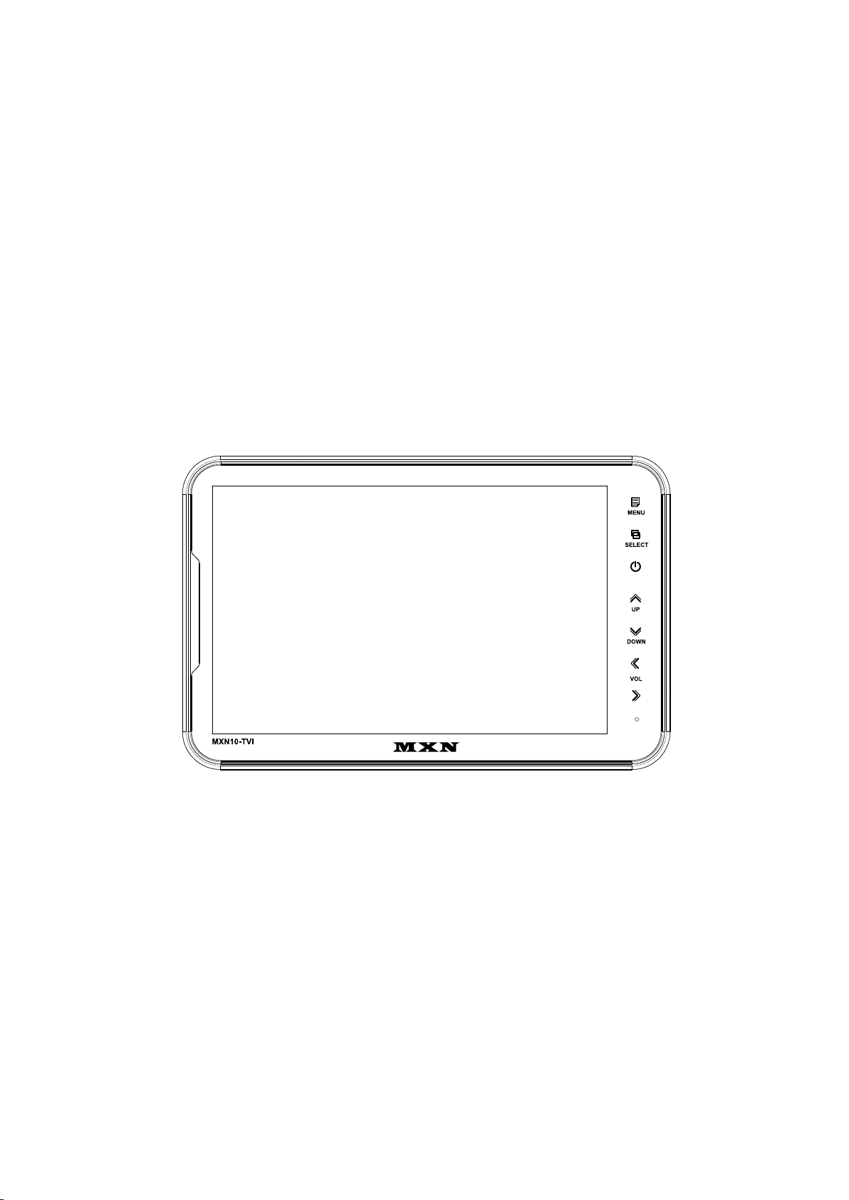
10.1” DIGITAL 3CH LCD
ALL ROUND VISION MONITOR
Model: MXN10-TVI
OWNER’S MANUAL
PLEASE READ CAREFULLY BEFORE
USING THIS PRODUCT.
Design and specifications are subject to change without notice.

INDEX
PACKAGE CONTENTS 03
OPERATION 04
SYSTEM SETTINGS
MENU STRUCTURE 05
FUNCTION 06
PICTURE MENU 07
NORMAL/MIRROR 07
AUDIO 08
TRIGGER AUDIO 08
CAMERA TRIGGER 09
DISTANCE MARKER 09
MARKER 09
DISTANCE MARKER ADJUSTMENT 10
AUTO PICTURE SCAN 11
CAMERA NAME 11
SPEED SWITCH 12
MENU
SPLIT 13
MANUAL SELECTION 13
MENU LOCK ON/OFF FUNCTION 14
AUTO PICTURE SCAN ON/OFF FUNCTION 14
CONNECTIONS
CAMERA INPUT 15
INSTALLATION
BRACKET 16
INSTALLATION OF HEAVY DUTY MOUNTING BRACKETS 17
SPECIFICATIONS 18

MXN10-TVI Owner's Manual
03
03
ITEM Q’TY
MONITOR 1
CAMERA INPUT CABLE 1
HEAVY DUTY MOUNT 1
MOUNT SCREWS (Machine Screw, M5 / 12mm) PH M5x12 4
BRACKET SCREWS (Tapping Screw, M5 / 25mm) TH 1, M5x25 4
MANUAL 1
PACKAGE CONTENTS
MONITOR MANUAL
CAMERA INPUT CABLE
BRACKET SCREWS MOUNT SCREWS HEAVY DUTY MOUNT
10.1” DIGITAL 3-CHANNEL-
SWITCHING LCD MONITOR
Model: MXN10-TVI
OWNER’S MANUAL
PLEASE READ CAREFULLY BEFORE
USING THIS PRODUCT.
Design and specifications are subject to change without notice.
10.1” HD LCD MONITOR
04
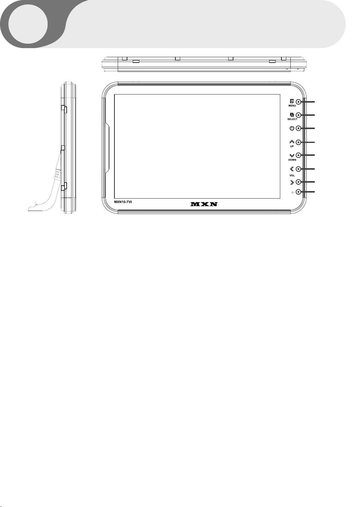
OPERATION
A
B
C
D
E
F
G
H
A. MENU
Press [MENU] button for system settings.
B. SELECT
Press [SELECT] button to select the respective channel.
[CAM1 - CAM2 - CAM3 - SPLIT].
C. POWER
Press [POWER] button to turn on/off the monitor.
D. UP
Press [UP] button to navigate the menu for system settings.
E. DOWN
Press [DOWN] button to navigate the menu for system settings.
F. LEFT
Press [LEFT] button to adjust the monitor volume.
Use [LEFT] button to change OSD setting during system settings.
G. RIGHT
Press [RIGHT] button to adjust the monitor volume.
Use [RIGHT] button to change OSD setting during system settings.
H. DAY/NIGHT SENSOR (CDS)
Automatic brightness control sensor

MXN10-TVI Owner's Manual
05
05
SYSTEM SETTINGS
MENU STRUCTURE
Change the setting value by pressing the MENU button.
FUNCTION
Set functions on the monitor.
PICTURE
Set the color and brightness on the monitor.
NORMAL/MIRROR
Input video can be reversed
AUDIO
Set the audio ON/OFF.
TRIGGER AUDIO
Set the audio ON/OFF when entering the TRIGGER signal.
CAMERA TRIGGER
You can adjust the Screen settings with the corresponding TRIGGER signal is on.
DISTANCE MARKER
DISTANCE MARKER can be set according to the TRIGGER signal input.
AUTO PICTURE SCAN
Set the automatic sequence switching time.
CAMERA NAME
Set the camera name.
SPEED SWITCH
By receiving TACHO signal, you can set the operation at the corresponding frequency.
SPLIT
Display the camera video at the set position on the SPLIT screen.
MANUAL SELECTION
When the SELECTION button is pressed, the output screen is set.
FUNCTION
PICTURE
NORMAL/MIRROR
AUDIO
TRIGGER AUDIO
CAMERA TRIGGER
DISTANCE MARKER
AUTO PICTURE SCAN
CAMERA NAME
SPEED SWITCH
SPLIT
MANUAL SELECTION
10.1” HD LCD MONITOR
06
LANGUAGE
SYSTEM
DIMMER
DAY BRIGHT
NIGHT BRIGHT
AUTO POWER
BUZZER
RESET
SYSTEM INFO
ENGLISH
AUTO
AUTO
90
50
OFF
ON
>>
VER 1.00
FUNCTION
LANGUAGE
Provide 6 Multi-lingual OSD [ENGLISH, SWEDISH, DANISH, NORWEGIAN, DUTCH, FINNISH].
Select the preferred LANGUAGE.
SYSTEM
Select AUTO/TVI/AHD/NTSC/PAL
DIMMER (Automatic Brightness Control)
Select AUTO or OFF to enable Automatic or Manual brightness control.
REMARK: By activating the DIMMER AUTO function,
the monitor adjusts the brightness according to the environment.
DAY BRIGHT
Select the DIMMER as 『AUTO』, set the value of backlight on DAY mode(0~100).
NIGHT BRIGHT
Select the DIMMER as『AUTO』, set the value of backlight on NIGHT mode(0~100).
AUTO POWER
Select monitor activation functions as below.
[AUTO] The monitor remembers the last settings from its memory.
[ON] The monitor is turned on with the『Power-ON』mode automatically.
[OFF] The monitor is turned on with the『tSand-By』mode automatically.
BUZZER
Select BUZZER sound 『ON』 and 『OFF』.
RESET
Press “>>” button to enter the factory default settings.
SYSTEM INFO
Refers to the system information of the monitor.
SYSTEM SETTINGS
MXN10-TVI Owner's Manual
07
07
CONTRAST
BRIGHTNESS
COLOR
TINT
CAM1
CAM2
CAM3
50
50
50
50
NORMAL
NORMAL
NORMAL
PICTURE MENU
NORMAL/MIRROR
Press [LEFT/RIGHT] button to adjust the PICTURE of the monitor.
PICTURE MENU is for the settings of PICTURE from CAM1, CAM2, CAM3, SPLIT MODE.
Each camera picture (CAM1/CAM2/CAM3) can be switched between
NORMAL& MIRROR image.
FISHEYE
When using the FISHEYE camera, 『ON』 will calibrate the screen on the FULL screen.
SYSTEM SETTINGS

10.1” HD LCD MONITOR
08
CAM1
CAM2
CAM3
SPLIT
ON
ON
ON
ON
TRIG1
TRIG2
TRIG3
SP SW
ENTER
ENTER
ENTER
ENTER
TRIG1 AUDIO
VOLUME
ON
10
AUDIO
TRIGGER AUDIO
Audio ACTIVATED Mode in normal mode.
When the mode is [ON], audio will be on (activated)
When the mode is [OFF], audio will be off (mute).
Audio ACTIVATED Mode in Trigger mode.
Choose the trigger and then press [ENTER].
The Audio settings menu will be shown as below.
When the mode is [ON], audio will be on (activated).
When the mode is [OFF], audio will be off (mute).
The user can adjust the volume.
SYSTEM SETTINGS
AUDIO
AUDIO
AUDIO
AUDIO
AUDIO
AUDIO
AUDIO

MXN10-TVI Owner's Manual
09
09
Select of DISTANCE MARKER. or ___
CAMERA TRIGGER
DISTANCE MARKER
MARKER
Select ON to have DISTANCE MARKER for CAM1, CAM2, CAM3
DISTANCE MARKER is displayed as the trigger signal is activated.
TRIGGER 1/2/3 (Trigger source selection)
Select the required trigger source at CAM1/CAM2/CAM3/SPLIT
REMARK
TRIGGER PRIORITY: TRIGGER 1 > TRIGGER 2 > TRIGGER 3
TRIG. DELAY
When a TRIGGER wire is connected to a pulse DC power signal (e.g.direction indicator lights) then the
[TRIGGER DELAY] function avoids repeating ON/OFF of the monitor.
SYSTEM SETTINGS
TRIGGER1
TRIGGER2
TRIGGER3
TRIG1. DELAY
TRIG2. DELAY
TRIG3. DELAY
TRIGGER1
TRIGGER2
TRIGGER3
MARKER
CAM1
CAM2
CAM3
2
2
2
ON
OFF
OFF
10.1” HD LCD MONITOR
10
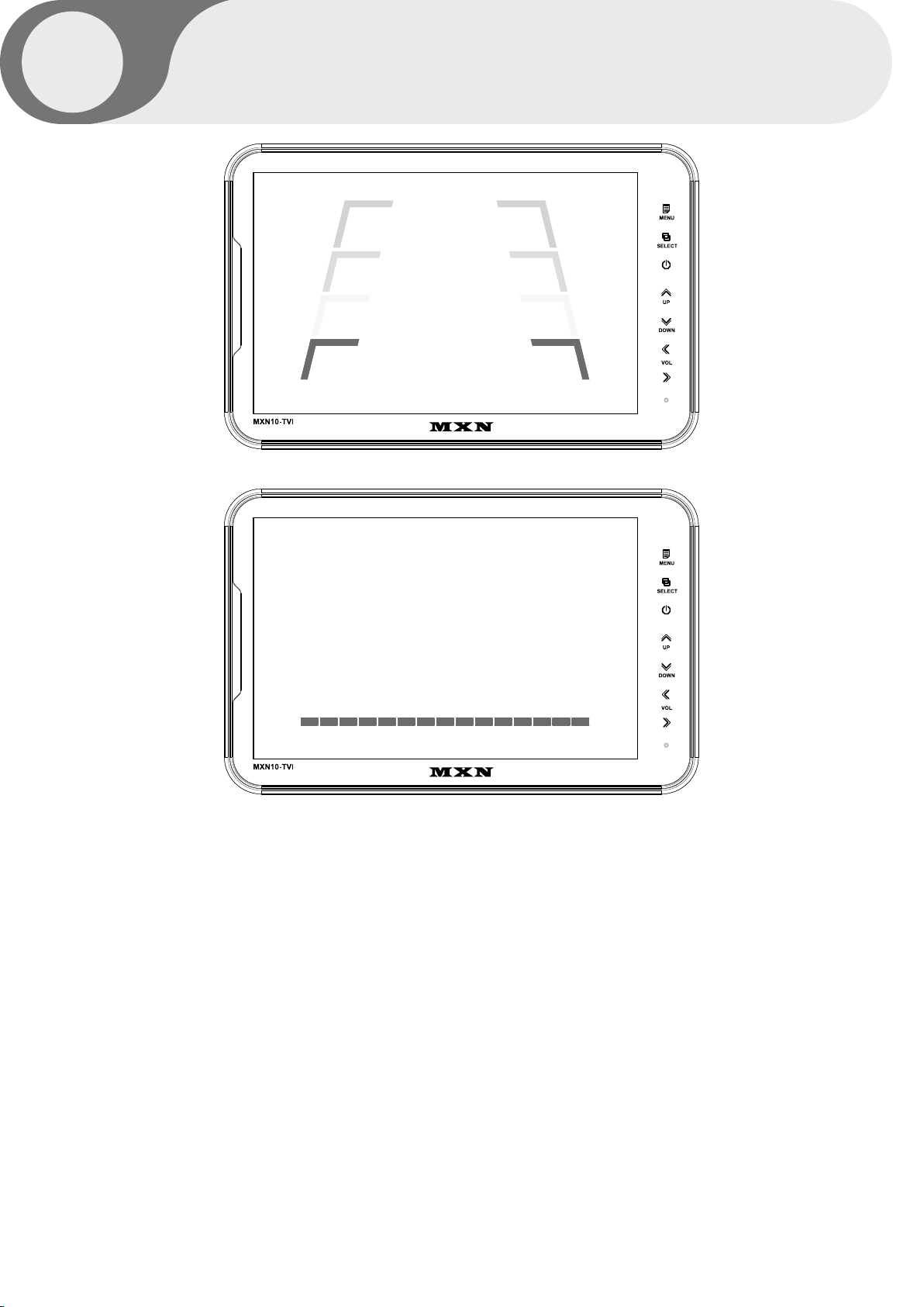
DISTANCE MARKER ADJUSTMENT
Users can make adjustments by pressing the SELECT button in the menu.
(It is not available on the split mode screen)
Marker A- Parking line
The left/right/both markers will be selected in order each time you press the SELECT button.
When the marker is red it can be adjusted UP/DOWN or LEFT/RIGHT.
When both distance markers are RED, you can adjust both markers LEFT/RIGHT/UP/DOWN.
When the left distance marker is RED, the left marker can be adjusted LEFT/RIGHT.
When the right distance marker is RED, the right marker can be adjusted LEFT/RIGHT.
Marker B- Horizontal line
Users can adjust the line UP/DOWN.
Users can adjust the horizontal line by pressing [UP/DOWN] buttons.
SYSTEM SETTINGS
>> Marker A
>> Marker B
Table of contents
Other MXN Monitor manuals


