manuals.online logo
Brands
  1. Home
  2. •
  3. Brands
  4. •
  5. My Fireplace Blower
  6. •
  7. Fireplace Accessories
  8. •
  9. My Fireplace Blower GA3450TA User manual

My Fireplace Blower GA3450TA User manual

Installation Videos:
MY
FireplaceBlower MyFireplaceBlower.com:
Installation Instructions:
Installer is responsible to check local codes
and read all instructions prior to installation.
Layout designed in U.S.A. © 2022
Drywall dust or other fragments may be present in your replace’s vent space, clean this area before you install the
blower kit. Any bearing or motor damage resulting from this condition is not covered by the warranty policy.
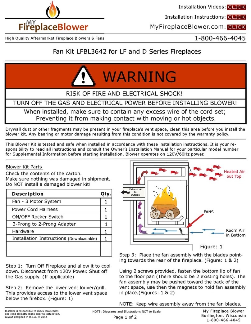
Instructions for Design Version - GA3450TA Blower Kit
This Blower Kit is tested and safe when installed in accordance with these installation instructions. It is your re-
sponsibility to read all instructions and consult the Owner’s Installation Manual for your particular model number
for Supplemental Information before starting installation. Blower operates on 120V/60Hz power.
CLICK
High Quality Aftermarket Fireplace Blowers & Fans 1-800-466-4045
Check the contents of the carton.
Make sure nothing was damaged in shipment.
Do NOT install a damaged blower kit!
Blower Kit Parts
Step 1: Turn O Fireplace and allow it to cool down.
Disconnect from 120V Power. Shut o the Gas supply.
Remove the louver which covers the lower vent space
below the rebox.
Figure: 1
CLICK
CLICK
NOTE: Diagrams and Illustrations NOT to Scale
Page 1 of 4
WARNING
RISK OF FIRE AND ELECTRICAL SHOCK!
TURN OFF THE GAS AND ELECTRICAL POWER BEFORE INSTALLING BLOWER!
When installed, make sure to contain any excess wire of the cord set;
Preventing it from making contact with moving or hot objects.
Description Qty.
Blower - with Mounting Bracket
Thermodisc / Heat Sensor
Variable Speed Control
Cord Set
Installation Instructions (Downloadable)
1
1
1
1
1
1
Packet of 6 Screws
My Fireplace Blower LLC
Burlington, Wisconsin
1-800-466-4045
•WHITE Wire - Connects to Metal Spade on Motor
•BLACK Wire - Connects to Variable Speed Control
and Heat Sensor, then to Metal Spade on Motor
•GREEN Wire - Push onto Metal Ground tab on side
of Motor (Figure: 4)
•Lay cord set on oor and connect wires (Figure: 1).
Plug Power Cord into “Live” Outlet. Test Blower operation
by placing ame to Silver Disc of Heat Sensor for 10
seconds. Verify Speed Control and Rocker Switch are in
“ON” Position. (ON is AUTO) (Figures: 1, 7 & 9).
* You may remove the Variable Speed Control and/or
Heat Sensor if you choose not to use them.
*
*
•Push disconnects together, one plastic insulator
ts inside the other. Black and White wires can go
to either Metal Spade on Motor, does not matter
which one.
Rocker Switch
ON(Auto) / OFF
Heat Sensor /
Thermodisc
Green
White
Green
On
110/115V
Blower
Motor
Black
Off
1
OFF
White
Black
Black
White

Figure: 2
CLICK
Figure: 3
Installer is responsible to check local codes
and read all instructions prior to installation.
Layout designed in U.S.A. © 2022
NOTE: Diagrams and Illustrations NOT to Scale
Page 2 of 4
MyFireplaceBlower.com:
Step 2: Removing Upper & Lower Louvers for access
to install Blower and Power Cord with Cord Set.
See (Figure: 2) for illustration of “Fin” or “Slit”
Louver types. Typically, screws are securing the
Louvers in place.
•A “Cross Member” or “Hood” may need to be
removed also (Figure: 2).
•Pull Louver Assembly straight out from replace.
My Fireplace Blower LLC
Burlington, Wisconsin
1-800-466-4045
Step 3: Removing Valve Cover Shield
•Open bottom Louver Assembly by swinging the
assembly down (Figure 3).
•Using short Phillips screwdriver, remove screw
under center of Cross Member if necessary.
Rotate Valve Cover Shield clockwise and slide out
(Figure 3 - #1).
•IMPORTANT: Do not remove Side Screw on left side
of Valve Cover Shield. Slide Valve Cover Shield o
Side Screw (Figure 3 - #2).
where you purchased this kit or DESA International at 1-800-972-
Upper Louver
Assembly
Blower Bracket
Mounting Holes
Hood and Upper Louver with “Slit” Formations
Hood
Cross Member and Upper Louver “Fin” Assembly
Blower Bracket
Mounting Holes
Upper Louver
Assembly
Cross Member
WARNING: Never attempt to service Fireplace
while it is plugged in, operating, or hot. Burns
and electrical shock could result.
Bottom Louver
Panel
Side
Screw Valve Cover
Shield
Side
Screw
Removing Valve Cover Shield
Firebox
Frame Support
Ring
Bushings
Step 4: Installing Blower
•Note: If you are using a mantel with your
heater, see (Figure: 4). If your heater is
Built-In Installation, see (Figures: 4 & 5)
for where Power Cord plugs into the Outlet
Receptacle.
•In top of heater cabinet, locate four mount-
ing holes on Back Wall. Align the four holes
with those on blower bracket assembly.
Secure blower bracket assembly to Back
Wall with 4 screws and place Heat Sensor
on Compartment Floor to the Right of
Blower (Figure: 4).
•Route Cord Set through hole in lower left
Side Panel. Pull Cord Set through lower
opening above where Valve Cover Shield
was removed. (Figure: 4.)
•Insert the 3 wires of Cord Set into one of
the round holes of Valve Cover Shield
Backing and through Rectangular Hole in
front of Valve Cover Shield (Figure: 4).
•Reconnect Green, White and Black wires to
where they were previously connected.
•Install switch plate on Valve Cover Shield
with 2 screws provided (Figure: 6)
CLICK
Installer is responsible to check local codes
and read all instructions prior to installation.
Layout designed in U.S.A. © 2022
NOTE: Diagrams and Illustrations NOT to Scale
Page 3 of 4
MyFireplaceBlower.com:
My Fireplace Blower LLC
Burlington, Wisconsin
1-800-466-4045
Figure: 4
Figure: 5
Step 5: Reinstall Valve Cover Shield (Figures: 3 & 4).
•Route power cord out of cabinet by inserting it through
hole on lower Side Panel (Figure: 4).
•Note: If you are using a mantel with your heater, see
(Figure: 4), if your Fireplace is Built-In see Below.
For Built-In Installation, reference (Figure: 5) for
location where the Power Cord plugs into the Outlet
Receptacle. *A licensed electrician must install the
Outlet Receptacle from the incoming electrical supply
to Valve Cover Shield in compliance to Local or
National Code (Figure: 5).
OFF
ON
For Built-In
Install snap bushings found in hardware kit into both holes
Make sure the wire harness is firmly connected to all
Cord Set
Blower
Assembly
Screw
Power
Cord
Valve
Cover
Shield
Valve Cover Shield Backing
Cord
Set
Switch Bracket
Rocker
Switch
Compartment
Floor
Hole to Channel Wires
in Compartment Floor
Power
Cord
Valve
Cover
Shield
Valve Cover
Shield Backing Clamp Connector
(not included)
* Outlet
Receptacle
MY
FireplaceBlower
NOTE: Diagrams and Illustrations NOT to Scale
Page 4 of 4
Installations in Canada must conform to the current CAN/CGAB-419.1 and .2 Gas Installation Code and local regula-
tions. When installing the blower fan kit, it must be electrically grounded in accordance with CSA C22.1 Canadian
Electrical Code Part 1 and/or Local Codes.
Installations in the USA must conform to local codes, or in absence of local codes or the National Fuel Gas Code,
ANSI Z223.1-1988. When installing the blower fan kit, it must be grounded in accordance with local codes, or in
absence of local codes, with the National Electrical Code, ANSI/NFPA 70-1987.
My Fireplace Blower LLC produces and sells aftermarket replace blower kits; which require consultation
of an Owner’s Installation Manual from the Manufacturer of a particular replace model number for in-
stallation. During Installation of a replace blower kit or replacement blower, refer to the Owner’s Instal-
lation Manual for your particular replace model to obtain supplemental information. My Fireplace Blower
LLC is not responsible for any damage incurred during installation or resulting from installation of a re-
place blower kit, which was directed and/or conducted from the information within this document.
Installation Videos:
Installation Instructions:
Figure: 7
CLICK
CLICK
CLICK
Installer is responsible to check local codes
and read all instructions prior to installation.
Layout designed in U.S.A. © 2022
My Fireplace Blower LLC
Burlington, Wisconsin
1-800-466-4045
MyFireplaceBlower.com:
Figure: 6
Step 6:
•Reinstall Upper and Lower Louvers; If gas supply
and/or 120 Volt Power are Turned O, turn them
back on.
•Plug fan kit into 120-Volt grounded power supply
and test operation. (Figure: 10)
•The ON(AUTO)/OFF Rocker Switch controls
power to the blower (Figure: 7). The Blower will
not come on and shut o immediately with the
Heat Sensor installed.
Valve Cover
Shield
Switch
Bracket
Screw
3 Prong Plug
Grounded Outlet
ON
OF
F
ON (Auto) / OFF Switch
SMALL DIAL
The fan will not run until the Thermodisc / Heat Sensor reaches approximately 120°F
and the Variable Speed Control is turn to the “ON” Position! This means the Heat
Sensor must be in contact with a hot spot on the underside of the Firebox.
•To adjust minimum speed:
Rotate clockwise to decrease
low-end speed; counter-
clockwise to increase low-end
speed. (Figure: 8)
•Turn the dial to counter-
clockwise to increase
speed until it clicks o,
turn right to reduce
speed. (Figure: 9)
Figure: 8
Figure: 9
Figure: 10

Other My Fireplace Blower Fireplace Accessories manuals

My Fireplace Blower GFK-160A User manual

My Fireplace Blower

My Fireplace Blower GFK-160A User manual

My Fireplace Blower FBL3642 Fan Kit User manual

My Fireplace Blower

My Fireplace Blower FBL3642 Fan Kit User manual

My Fireplace Blower BLOT240 User manual

My Fireplace Blower

My Fireplace Blower BLOT240 User manual

Popular Fireplace Accessories manuals by other brands

Vents KAM user manual

Vents

Vents KAM user manual

CMC Royale Heat Exchanger Installation & operating instructions

CMC

CMC Royale Heat Exchanger Installation & operating instructions

FireplaceXtrordinair DVS FACE FPX 32 user manual

FireplaceXtrordinair

FireplaceXtrordinair DVS FACE FPX 32 user manual

Valor LT1 2500K quick start guide

Valor

Valor LT1 2500K quick start guide

Dimplex EMP-400 install guide

Dimplex

Dimplex EMP-400 install guide

pleasant hearth IRIS SCROLL quick start guide

pleasant hearth

pleasant hearth IRIS SCROLL quick start guide

HITZE TRIBOX TRI54x54x53.G installation manual

HITZE

HITZE TRIBOX TRI54x54x53.G installation manual

Hearth and Home Technologies HEAT-ZONE-GAS installation instructions

Hearth and Home Technologies

Hearth and Home Technologies HEAT-ZONE-GAS installation instructions

Lopi 250-05675 manual

Lopi

Lopi 250-05675 manual

Enclume COUNTRY HOME FIREPLACE TOOL STAND FPTS2 Assembly and installation instructions

Enclume

Enclume COUNTRY HOME FIREPLACE TOOL STAND FPTS2 Assembly and installation instructions

Superior Fireplaces WCT6940-FAC-BLK installation instructions

Superior Fireplaces

Superior Fireplaces WCT6940-FAC-BLK installation instructions

Lennox Hearth Products Elite Series DBv-CK-LP TO NG installation instructions

Lennox Hearth Products

Lennox Hearth Products Elite Series DBv-CK-LP TO NG installation instructions

Allen + Roth FPDS101BLK manual

Allen + Roth

Allen + Roth FPDS101BLK manual

Empire Comfort Systems DFF30RBL installation instructions

Empire Comfort Systems

Empire Comfort Systems DFF30RBL installation instructions

RSF Woodburning Fireplaces FDDHE Installation instruction

RSF Woodburning Fireplaces

RSF Woodburning Fireplaces FDDHE Installation instruction

Valor G4 792FTZ installation manual

Valor

Valor G4 792FTZ installation manual

Valor BSK645 installation instructions

Valor

Valor BSK645 installation instructions

EmberGlow VFF15NLA OWNER'S OPERATION AND INSTALLATION MANUAL

EmberGlow

EmberGlow VFF15NLA OWNER'S OPERATION AND INSTALLATION MANUAL

manuals.online logo
manuals.online logoBrands
  • About & Mission
  • Contact us
  • Privacy Policy
  • Terms and Conditions

Copyright 2025 Manuals.Online. All Rights Reserved.