Geovent GTE-250 User manual

INSTRUCTION MANUAL
www.geovent.com
Version 1.0 10.06.2022
HOSE REEL
GTE-250
Dimension: ø 250 mm

2

3
Contents
1.0 Introduction ..............................3
2.0 Safety ..................................3
2.1 General safety .......................... 3
2.2 Danger .................................3
3.0 Machine overview ........................ 4
3.1 Description ............................. 4
3.2 Intended use ............................ 4
3.3 Machine specifications .................... 4
3.3.1 Design ............................... 4
3.3.2 Technical data ......................... 4
4.0 Transport, handling and storage . . . . . . . . . . . . . 5
5.0 Assembly, installation and start of operation ... 5
5.1 Location ............................... 5
5.2 Installation ............................. 5
5.3 Control and test of the security system ........7
6.0 Commissioning .......................... 8
6.1 After installation ......................... 8
7.0 Control, test and maintenance .............. 8
7.1 Control ................................ 8
7.2 Maintenance .............................8
8.0 Cleaning ................................8
9.0 Troubleshooting ......................... 8
10.0 Dismantling, disabling and scrapping ....... 11
11.0 Dimensions ........................... 11
12.0 Liability .............................. 11
13.0 Declaration of conformity ................ 12
1.0 Introduction
This manual is made and designed in order to facilitate
the best and most secure interaction with the product.
The manual is relevant for people involved in transpor-
tation, stocking, installation, using, maintaining and all
other thinkable interaction with the product.
The manual must be read in full and understood before
interacting with the product.
When the manual has been read and understood in full,
the table of contents can be used to find the relevant
information in each case.
The product is manufactured by:
Geovent A/S
Hovedgaden 86
DK-8861 Løgstrup
DENMARK
Tel.: (+45) 86 64 22 11
E-mail: [email protected]
www.geovent.com
This manual is to be used for all interactions with the
product including: Transportation, stocking, installation,
operation and maintenance.
This product is marked with: (example)
2.0 Safety
2.1 General safety
Carefully read this manual before use and observe the
safety instructions in order to avoid injuries!
Keep this manual in a safe place!
Secure that all users of the product have read this ma-
nual and that they follow the instructions as described.
Observe all instructions marked on the product!
Observe the indications of the manufacturer.
Never use the product if you are in doubt about how it
works or what you should do.
When doing maintenance follow the instructions in chap-
ter 7.0.
Do not modify the product or use spare parts from other
suppliers than Geovent, as this may hamper the product
and the function.
2.2 Danger
You must wear safety gloves when handling or using the
product to protect your hands from scratches etc.
Be aware that the product may tilt when you move it.
You must handle the product with care and tie it safely to
the truck or the fork lift when it is in transport.
Follow the instructions in chapter 7.0 when the product
is maintained.
When handling the product be sure that the there is no
risk for the installer, and secure that there are no people
around the product, secure that the product cannot fall
down risking to injure persons or subjects.

4
The product is not to be used in areas categorised as
ATEX zones, e.g. with dust from aluminium, flour, wood,
and other mediums that present an explosion hazard.
If a repair is not possible you should dispose of the pro-
duct. Please follow the instruction for disposal in chapter
10.0.
3.0 Machine overview
3.1. Description
Geovent hose reel for use for extraction of exhaust gas
or equivalent gas and polluted air.
3.2 Intended use
The Geovent hose reels are suitable for the extraction of
exhaust gasses, welding smoke and grinding dust, etc.
Do not use hose reels in areas categorized as ATEX-zo-
nes, e.g. for the extraction of aluminium dust, flour, texti-
le dust, nor for sawdust or other media, which are con-
nected with danger of explosion.
3.3 Machine specifications
3.3.1 Design
End plates: Coated RAL 7015
Discharge: ø250 mm nozzle
Frame: Galvanized steel frame.
Bearing by the drive side: Spherical ball bearing. The
bearing is maintenance-free.
Hose guide: Black PVC pipe.
GTE - motor - technical data:
• Motor: 230V/50Hz 410W 1,79A.
• Torque: 120Nm
• Speed: 9 rpm
• Max. No. of coils: 27 revs.
• Max. power time: 4 min.
• Motor diameter: 45 mm
• Length of cable: 190 cm
• Temperature protection: ~ 140 °C
• Temperature area: -15 / +80 °C
Remote control:
The frequency of transmission is at 868MHz.
Battery: 3V CR2430 H
3.3.2 Technical data
Dimensions
Model/Dimension Height
[mm]
Width
[mm]
Depth
[mm]
GTE-1700-xx-250 1405 1683 1262
Model/Dimension Weight
[kg]
Ø
[mm]
GTE-1700-xx-250 174 250
Temperature extracted air: Depending on the
hose used.
Temperature surroundings: 0 - 50°C
Noise data
The hose reel itself does not emit any noise (however, it
may emit a little noise during coiling). The noise level pri-
marily depends on the relation between the diameter of
the hose and the volume of the extracted air (wind roar).
Optimum air volume
Several factors are important when selecting the correct
hose reel. Depending on the application, use the table
below as a guideline for the volume of air, requested for
various requirements.
Type of vehicle Recommended air
volume
Recomm.
hose dimen.
Train /
Large vehicles 2000-3000 m³/h ø250 mm
The details of the table above apply to idle running and
are only intended as a guideline. Various applications
may involve situations in which deviations from the table
occurs.
Circuit breaker max. 13A

5
4.0 Transport, handling and storage
During transport in a truck or in another means of trans-
portation the product must be securely packed in a box
or a pallet and covered with a water proff material.
The product must be securely stowed in the truck so that
it will neither tilt nor shift during transport.
During transport over a short distance e.g. in a stock or
a factory, the product can be moved by means of a for-
klift or a stabeler.
When moved it must be secured that the product does
not tilt or shift. And it must be secured that the limitations
of the means of transportation is not exceeded.
Secure that there are no people around the product,
when the product is moved.
The product must be placed in a dry place and covered
securely, in order to secure that moist, metal parts or
other substances do not damage the product.
It is not allowed to place anything on top of the product.
5.0 Assembly, installation and start of
operation
5.1 Location
The hose reel is suitable both for mounting in the ceiling
as well as on the wall. Ceiling mounting is the best opti-
on, if possible, since this position secures the optimum
operation of the hose reel.
5.2 Installation
When the product is installed it is important that there is
space for
• Assembly and servicing of the hose reel.
• Connections for piping and automation.
Procedure:
1. Wear gloves. Remove the shield on the side of the
hose reel.
2. Loosen the hose reel from the pallet.
3. Carefully roll the hose reel onto another pallet covered
with cardboard or similar.
4. If necessary, use eye bolts when craning the hose
reel.
Max. weight hanging
Including nozzle: 15 kg
Max. weight hanging
Including nozzle: 15 kg
Mount on ceiling or wall.
Max. weight hanging
Including nozzle: 15 kg
Max. weight hanging
Including nozzle: 15 kg
Mount on ceiling or wall.

6
1. Firmly attach the hose reel to the ceiling or on the wall.
The wall or the ceiling must be capable of withstan-
ding a pull of at least 500 kg in order to prevent a
collapse. It must be ensured that the number of bolts
and the strength of the bolts are sufficient to keep the
hose reel clamped.
2. Important! Mount the hose reel on a plane and stable
installation surface and ensure that the reel/mounting
frame is not twisting. I.e. it must be able to rotate al-
most without friction around its own shaft. If the reel
twists, it may reduce the functionality or the service
life of the hose reel.
3. Connect the piping to the hose reel.
Since the inlet of the hose reel is a ø250 mm nipple,
use a ø250 mm coupling. Make sure not to twist the
hose reel, since it could damage the bearings.
4. Nozzle and automatics are factory-mounted optional
extras. Please order these parts when ordering the
hose reel.
Programming remote
New remote
When programming a new remote control, it is im-
portant that only the respective hose reel is turned
on.
Read all stages through to start programming.
A supply cable with plug for 230V / 50 Hz is supplied
from the factory.
There must be possible for the power supply for each
hose reel to be interrupted individually.
The remote control is programmed for each hose reel.
Only activate the hose reel, when you can see that there
is no obstacles and it has been adjusted correctly.
We recommend assigning a permanent place to keep
the remote control, e.g. on the wall or on the lift by the
individual workstation.
1. 2.
2.1.
1.
2.
Adding an extra remote control
Code an additional remote control with the existing
remote control.
Read all stages through before you start programming.
Press the button on the back
of the new remote control once
with the programming key.
Press the button on the back
of the new remote control once
with the programming key.
When the controller howl, press
the centre button of the existing
remote control to activate the
programming.
The controller howls for 5 se-
conds. Press the middle button on
the new remote control within the
5 seconds.
Press the programming button on
the back of the remote control 3
times.
Within 5 seconds, press once on
the existing remote
centre button. When cleared, the
controller will beep constantly.
When the controller howls,
press the middle button once
within 5 seconds, and the
controller beeps briey.
Delete remote
It is important that the hose reels that you want to
remove the remote control from are on.
Read all stages through before you start programming.
Blå
Jordforbindelse
Blå
Brun
Gul/Grøn
Gul/Grøn
230VAC
OPEN
CLOSE
COM
Brun
Sort
Motor
Forsynings-
spænding

7
5.3 Control and test of the security system
Always check whether the fan supplies the volume of air,
for which the equipment was dimensioned. If the correct
suction is not present, then there is an increased risk of
the hose melting, when extracting warm exhaust gas-
ses.
GTE – electrical motor
As standard, the hose reel GTE with electrical motor and
remote control comes pre-programmed ready for use.
Please note: Always adjust the hose reel to the wor-
king area by fine-tuning it.
Adjustment of end stop:
Adjust stop by means of a screwdriver.
750 mm
375 mm
ø12 mm x 22
Standard slangerulle
1092 - 1112mm
Slangerulle 1400
1492 - 1512mm
Hose reel
1580 mm
1560 mm
- +
+ -
Red = End stop
when coiled up (up)
White = End stop
when coiled down
(down)
The remote control will be programmed from the factory.
Connection of wall-mounted control (via cable)
On the TD terminal there is a cable for the one-pole
toggle switch (automatic reset).
Such switches are available in various shapes and
variations
Function: The first push activates the reel, the second
push stops it. The third push starts the reel again, howe-
ver, the drive reverses, etc.
Mounting of automatic start/stop
The switch for automatic start/stop (max. 250V 10A) (if
ordered, it is factory-mounted) must be mounted under
the protection shield. The two-pole switch sends a signal
to the control panel LWS/Multibox when activated and/or
a fast action motor damper.
See wiring diagram on page 10
Installation of GTE - Motor
Mounting sketch
TD

8
6.0 Commissioning
Never use the hose reel without connecting it to a swit-
ched-on fan (and an open damper). If there is no air pre-
sent or if the volume of air is not correct (too low), then
the hose will melt or become deformed (turn oval).
In cases where the exhaust gasses have a temperatu-
re higher than 150°C (e.g. if the motor starts running),
then the hose may also melt and/or become deformed.
In such cases, you must ensure to adapt the material/
solution to the job. Check the temperature of the exhaust
gasses before commissioning. Do so by testing with a
probe thermometer in the airflow.
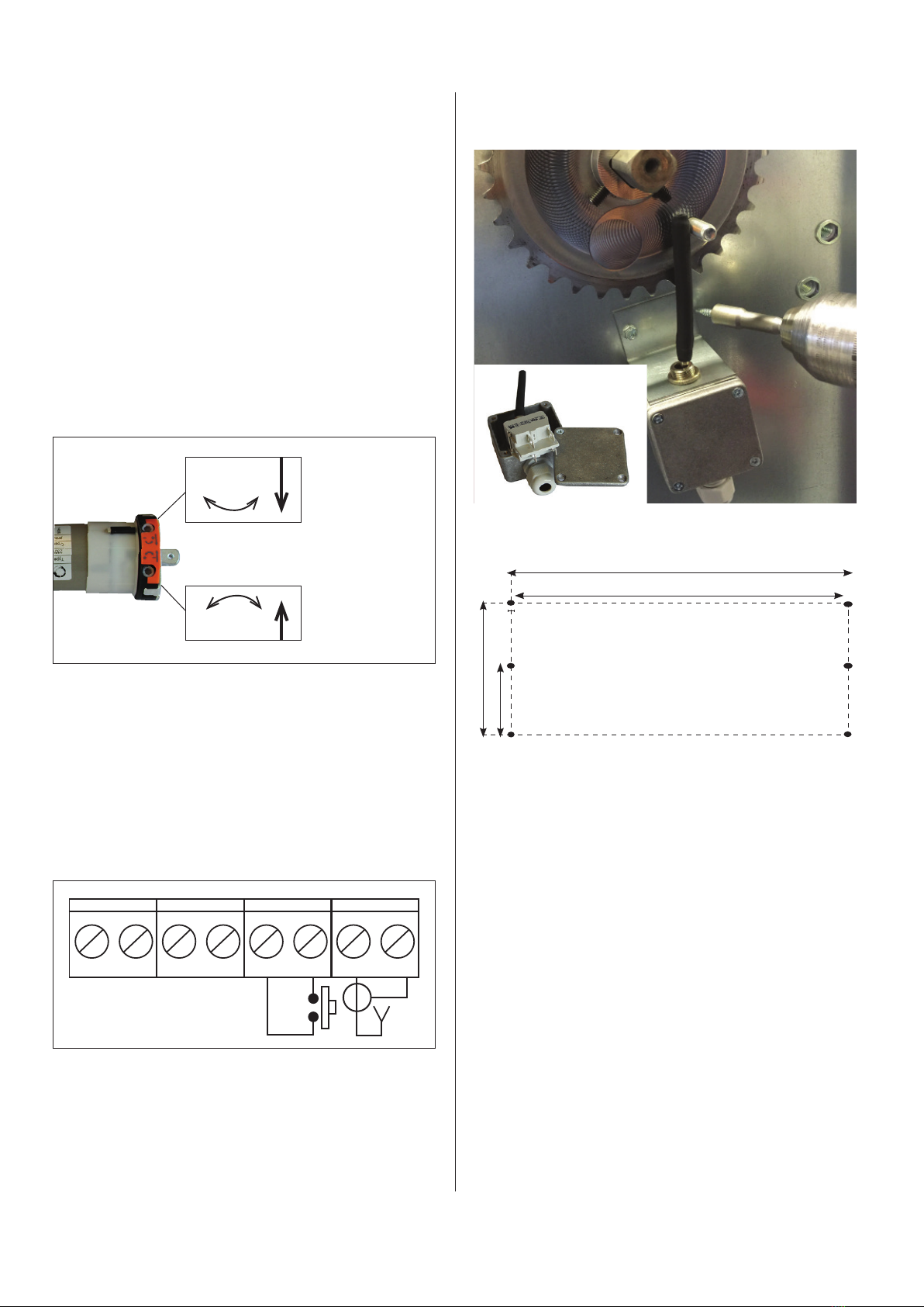
It is important that the fan is always switched on during
use of the hose reel. If you have automatics ensuring
that the fan starts, when using the reel, it is important
that the hose reel is not running in the opposite directi-
on at the commissioning, so that the actuation lever tips
back. If this happens, then the fan will be deactivated
and the hose may melt.
Thus, always check that there is suction on the nozzle,
when fixing it to the hose/upon commissioning.
IMPORTANT! WE SUPPLY HOSE REEL GTE PRE-
PROGRAMMED. I.E. THE REMOTE CONTROL IS CO-
DED FOR THE INDIVIDUAL HOSE REEL AND THE
END STOP IS SET.
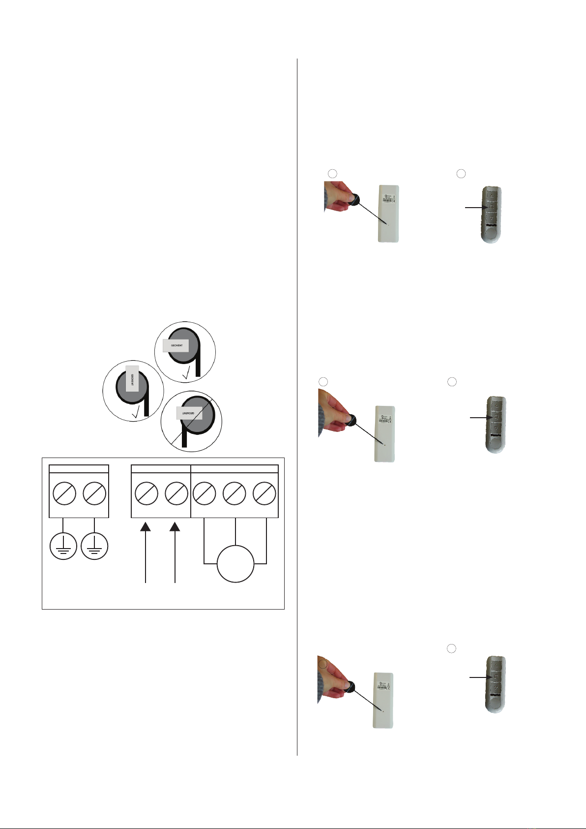
Using the remote control:
The top button (UP), coils up the hose. A push on the
button (DOWN) coils the hose down. The button in the
middle stops the hose. If you push the opposite directio-
nal button during operation, the drive will stop and then
start turning in the opposite direction.
The hose reel is not functioning as intended, if:
• Unauthorized parts are mounted on the Hose reel.
• The total lifting capacity of 22 kg has been exceeded.
See section 5.2 for re-programming the roller.
Coiling up:
When coiling the hose up, it is important to guide the
hose by hand.
The hose must not be rolled up when it is hot
6.1 After installation
Check the installation according to chapter 5.3.
7.0 Control, test and maintenance
7.1 Control
Check the installation according to chapter 5.3.
7.2 Maintenance
Periodic maintenance:
• At least once every year, grease the V-ring of the
hose reel in order to avoid deformation. Also, grease
between pipes and connecting branch. Failing to
maintain the hose reel will lead to squeaky noise
coming from the hose reel.
• You cannot carry out maintenance on the hose, how-
ever. To secure a long service life, try to avoid run-
ning over the hose with vehicles etc., make sure to
extract adequate volumes of air and ensure that the
hose does not bend too much immediately after the
exhaust pipe.
• Measure the volume of air on the hose reel at least
once every year. If the volume of air is inadequate, it
may result in burning a hole in the hose.
At least once every year, arrange for an authorized
service engineer to carry out an inspection of the
complete extraction system.
8.0 Cleaning
The outside of the product is cleaned with a vacuum
cleaner or a cloth.
9.0 Troubleshooting
In case of problems with the hose reel, check the fol-
lowing:
Problems with the operation of the hose reel:
• The pawl of the hose reel will not engage. Typically,
the pawl is worn or the spring for the pawl is defective.
Exchange defective parts.
• The hose reel coils slowly. Perhaps it is mounted on
an uneven surface, or the bracket of the hose reel is
deformed. Rectify by mounting the hose reel on an
even surface or by correcting the bracket.
Noise problems
• If the hose reel emits a squeaking noise, typically, the
V-ring of the inlet bearing is defective or out of positi-
on. Rectify it by replacing the V-ring or by adjusting it.

9
Remember to grease it!
• The base on which the hose reel and the fan are
mounted is unstable.
• More air is extracted than what the product has been
dimensioned for. Use an adjusting damper.
Problems with the hose
• The hose cannot withstand high temperatures; there-
fore, holes may have been burnt into the hose.
This happens if there is not sufficient suction in the
system. Rectify by increasing the suction of air th-
rough the system or by extending the hose with 1
–2 m of high-temperature hose, or with a full-length
high-temperature hose, depending on the temperatu-
re. Also you can add ”false air” in order to reduce the
average temperature.
GTE – electrical motor
Troubles with the remote control
The range is too short:
• Roll out the aerial.
• Do not twist the aerial around the power supply cable.
• Reposition the aerial (do not extend it).
• Avoid placing it close to products emitting radio inter-
ference (e.g. overhead travelling cranes). Large volu-
mes of electromagnetic noise may result in reduced
range/function.
• If the LED is lit, normally, the battery in the remote
control is sufficiently charged.
• If during the past few weeks the range has become
shorter, replace the battery.
The range is subject to serious periodic variation/
fluctuation:
• The remote control operates at the frequency of 433
MHz. In case other signals are using the same frequen-
cy, it may reduce the signal significantly, since the re-
ceiver/motor will block the signals for security reasons.
• For example, weather stations or radio-controlled tem-
perature sensors typically emit signals in cycles of 30-
90 seconds lasting approx.1 second.
• Headsets can also emit radio signals, just as airports
and military zones may have equipment causing noise.
• Try testing another position – or deactivate all other
equipment.
• Weak battery? Exchange it.
Change to a cables connection, there is too much elec-
tronic noise..

10
3
1
3
2
4
Contact set.
Terminals
1 2 3
GFD Damper
1 2 3
54
Sensing coil
Machine/welder
N F
380 V
N F J FF
Power Smart
230 V
GFD Damper
1 2 3
1
3
2
4
Contact set.
Micro Switch
Ect.
230 V
GFD Power
1 2
GFD Damper
1 2 3
NO - blue
Common
- (Black)
NC - Grey
Terminals: Max.
external connection
250V, 6A
Functions:
Black/blue=Connect
Black/grey=break
MULTI COUPLING DIAGRAM - TERMINALS, MULTIBOX AND FREQUENCY INVERTERS
N L
GFD Power
1 2
N L N L
START/STOP SIGNAL FOR
FAN/MULTIBOX
230 V230 V
GFD Power
1 2
GFD Damper
1 2
GTE Hose Reel GTS Hose Reel
Multibox III
T1 T2 T3 T4 T5 T6 T7 T8 T9 T10
J N 0 8 9 10
230 V
Alarm
Start/Stop signal
SRC
AI
GND
GND
COM
DI1
380 V
L1
L1
L1
PE
Fi
R-
R+
ABB ACS 150
Start/Stop signal
U + V + W +PE
1
2
3
4
5
6
7
8
9
L
DI2
SRC
AI1
AGND
GND
DCOM
DI1
380 V
L1
L1
L1
PE
Fi
R-
R+
Fi
R-
R+
ABB ACH 580
Start/Stop
signal
U + V + W +PE
1
2
3
9
10
11
12
13
24V
+24V
SRC
AI2
GND
PW
COM
S1
400 V
T
S
R
PE
INVT GD20
Start/Stop
signal
U + V + W +PE
+24V
SRC
AI1
GND
PW
COM
S1
400 V
T
S
R
PE
INVT GD350
Start/Stop
signal
U + V + W +PE
+24V
CNO
MOTOR
230 V
GFD trafo
1 2
1 2 3
N L
1
3
2
4
When T4 (floating input)
is activated the Multibox is
activated and CTS and relay
motor in the bottom is
activated
Connect one of the
following frequency
inverters
T10 is only used
in MultiboxT10 is only used
in Multibox
T10 is only used
in Multibox
T10 is only used
in Multibox
Balance
contact
Contact set.
GFD Damper
Adjusting frequency inverter:
See manual - important parameters, must be adjusted:
Motordata: Typically parameter group 99
Ramp up/down: Typically parameter group 22
Frequency Max/Min: Typically parameter group 20 and 11
OBS - IMPORTANT
Jumper on the bottom (S1) must be switched from “I” to “U”
This will change output from current to voltage.
Remember to bridge GND and COM.
Adjusting Multibox III::
Quickguide - also see manual
P0: Version selector - select 530 (most common)
P1: Adjustment set point [Pa]
P2: Min. Alarm limits [s] at too low pressure
P3: Max. Alarm limit [s] at too high pressure
P10: Shows current pressure.
Multicoupling diagram for switches, MultiBox III and frequency inverters

11
10.0 Dismantling, disabling and scrapping
Deactive the product by disconnection the electrical
mains.
Dismantle compressed air pipes and other pipes
or wires etc.
The inside of the product must be cleaned by means of
a vacuum cleaner with a filter which suits the purpose.
The inside of the product must be cleaned by means of
a vacuum cleaner with a filter which suits the purpose.
Dismantle plastic parts and dispose of it according to
local regulations.
Dismantle the metallic parts by unscrewing screws and
bolts. Afterwards cut the larger pieces into smaller pie-
ces and dispose of it according to local regulation.
The packing material must be sorted according to local
regulation in order to be able to reuse the material.
11.0 Dimensions
Hose reel ø250 mm
12.0 Liability
Warranty
Geovent A/S grants a warranty for products, which are
defective, when it can be proved that the defects are due
to poor manufacture or materials on the part of Geovent.
The warranty comprises remedial action (repair or ex-
change) until one year after the date of shipment.
No claims can be made against Geovent A/S in relation
to loss of earnings or consequential loss as a result of
defects on products from Geovent.
Wear on parts such as filter cartridges and hose is not
included in the warranty.
User liability
In order for Geovent to be capable of granting the decla-
red warranty, the user/fitter must follow this instruction
manual in all respects.
Under no circumstances may the products be chan-
ged in any way, without prior written agreement with
Geovent A/S.
Please refer to the current sales and delivery conditions
at www.geovent.com

12
14.0 Spare part list
Art. No. Description
09-156 GeoFlex Exhaust HT ø254 mm
09-135 GeoFlex Exhaust HT-450 ø254 mm
13.0 Declaration of conformity
The manufacturer: GEOVENT A/S
HOVEDGADEN 86
DK-8831 LØGSTRUP
Hereby declares that:
The product: Hose reel
Model: Hose reel 1700 mm ø250 mm
Complies with the relevant parts of the following directi-
ves and standards:
Directive 2006/42 / EC of the European Parliament and
of the Council of 17 May 2006 on machines and amen-
ding directives 95/16 / EC.
This declaration is no more valid if changes are made to
the product by others than the manufacturer.
Authorized to collect the technical file:
Lise Cramer
Date: 10.06.2022
Position: Director
Name: Thomas Molsen
Signature: ____________________________

13

14

15
Table of contents