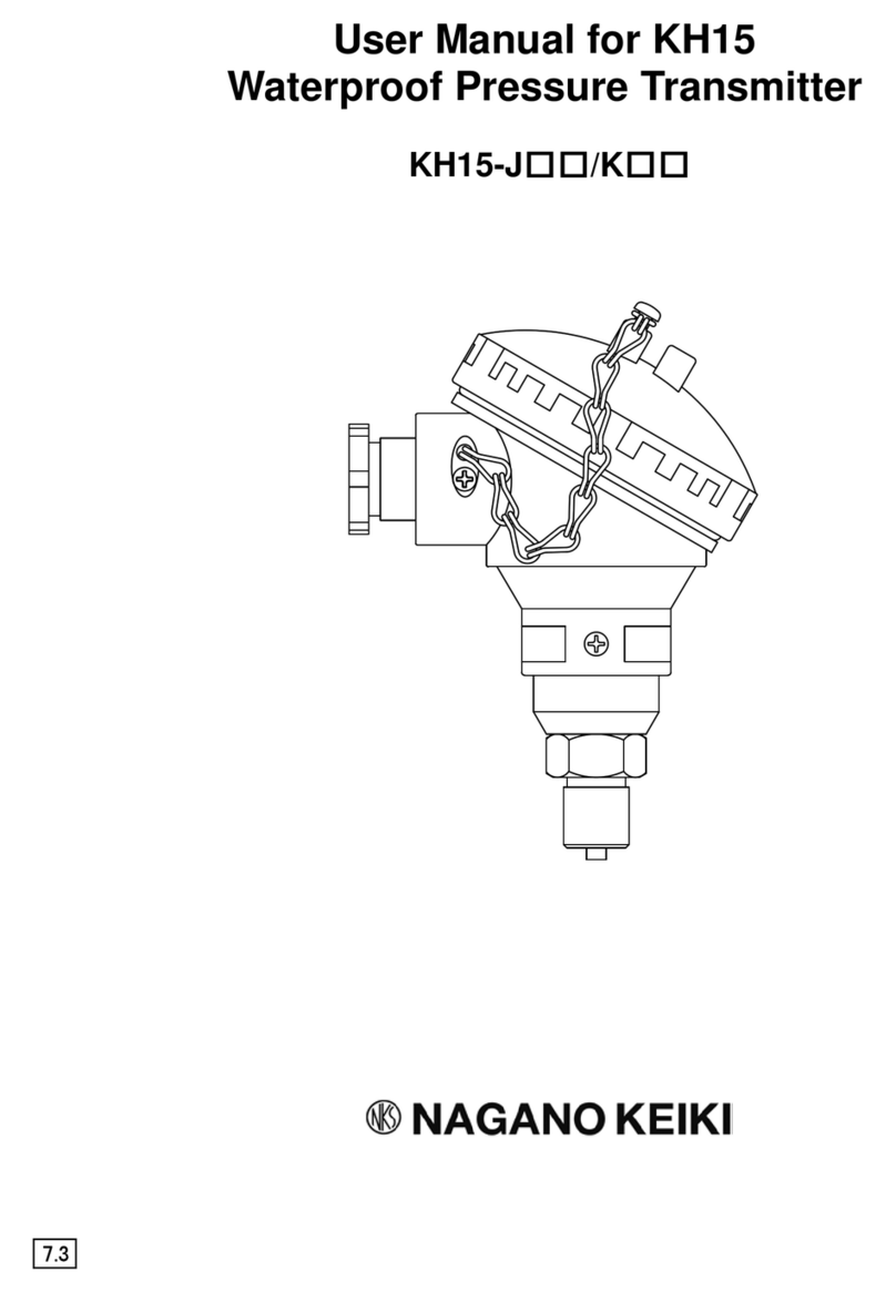
Nagano Keiki KJ55 Series User manual

1 TY-KJ55-002A Rev.3
User Manual for
KJ55 Intrinsically Safe
Pressure Transmitter
7.4

2 TY-KJ55-002A Rev.3
For Proper and Safe Use
Thank you for purchasing the KJ55 intrinsically safe pressure transmitter. To use this
product safely and properly, read this user manual carefully. This product is a marine
pressure transmitter conforming to the IEC intrinsically safe standards, which can be used
even in Zone 0 areas where explosive gas always exists. Incorrect use of it causes failures,
which may result in damage including faults or accidents.
Keep this manual safely after reading it so that you can always reference it.
■ Definition of Safety Terms
Safety precautions in this manual are categorized based on the following definition:
Indicates the risk that users may suffer from damage
including death or serious injury, and extremely high
urgency at the time of occurrence of risk.
Indicates the risk that users may suffer from damage
including death or serious injury.
Indicates the risk that users may suffer from minor injury
and the risk that only property damage may be caused.
■ Description of Graphic Symbols
Graphic
symbols
Meaning
Generally prohibited activities
Indicates prohibited activities in handling the product.
General instructions
Indicates activities based on instructions that users are forced to
conduct.
Other information
Indicates precautions, special operating methods, and other
important information.
DANGER
WARNING
CAUTION

3 TY-KJ55-002A Rev.3
■ Precautions for Handling Product
Do not give excessive load, vibration, and shock.
Damage to the product and release of a measured object may be
caused, which results in injury or damage to the surrounding
environment.
Do not apply pressure over the maximum allowable pressure.
Damage to pressure elements may be caused, which results in
injury or damage to the surrounding environment.
When a measured object is oxygen, do not use this product.
In case the product is damaged, oil reacts to oxygen, which causes
the risk of ignition or explosion.
Do not use this product for measured objects corrosive to
materials of wetted parts and gas contact parts.
This product is explosion-proof.
Do not use, install, store, or perform work that degrades the
explosive-proof performance in the environments listed below.
1) Installation that degrades the explosive-proof performance of
the intrinsically safe circuit
• A place with an ambient temperature of above 60 °C*1
• A place exposed to direct sunlight*1
• A place exposed to water such as rain*2
• A place where atmosphere contains moisture, salt, or sulfur
content*2
2) Wiring that degrades the explosive-proof performance of the
intrinsically safe circuit*3
3) Product inspection in a hazardous area*4
Do not use non-designated batteries and power supply.
Use of them causes failures, fires, or electric shocks.
If failures or malfunctions of this product may threaten human life
directly or cause harm to human bodies, do not use the product.
Do not modify this product.
Disassembly or modification of the product, or modification to add
new functions may cause harm to human bodies.
Conduct wiring correctly according to the wiring nameplate or the
wiring procedure described in the user manual.
Incorrect wiring may cause failures or fires.
!
WARNING

4 TY-KJ55-002A Rev.3
Use the product within the operating temperature range.
Otherwise, the product fails or is damaged, which causes injury or
damage to the surrounding environment.
*1 Install this product to avoid direct sunlight. Otherwise, the allowable intrinsically safe temperature of 60°C
is exceeded, resulting in degrading the intrinsically safe protective performance.
*2 Install this product to avoid rain and wind, sea breeze, and condensation. Otherwise, the case erodes,
degrading the intrinsically safe protective performance, or moisture in the air enters the case, degrading
the intrinsically safe insulating performance.
*3 For details, see "7. Wiring and Connection".
*4 Only an appearance check is allowed in a hazardous area. Be sure to perform other inspection checks in a
"non-hazardous" area.
Also, avoid electrostatic charge. To clean this product, use a water-soaked soft cloth.
Install the product according to the installation procedure
described in the user manual.
Contact us for repair.
Disassembly or modification of the product on your own may
cause failures.
CAUTION
!

5 TY-KJ55-002A Rev.3
Table of Contents
For Proper and Safe Use..........................................................2
■Definition of Safety Terms..............................................................................2
■Description of Graphic Symbols....................................................................2
■Precautions for Handling Product..................................................................3
Table of Contents ......................................................................5
1. Preface ...................................................................................6
2. Product Overview..................................................................6
■2.1 Features...................................................................................................6
■2.2 Operating Principles ................................................................................6
3. Specifications........................................................................7
■3.1 General Specifications.............................................................................7
■3.2 Intrinsically Safe Specifications ...............................................................8
4. Dimensions............................................................................9
5. Transportation and Unpacking..........................................10
■5.1 Precautions for Transportation ..............................................................10
■5.2 Precautions for Unpacking.....................................................................10
6. Installation and Removal....................................................10
■6.1 Transmitter.............................................................................................10
■6.2 Safety Barrier.........................................................................................10
■6.3 Cable......................................................................................................10
7. Wiring and Connection.......................................................11
■7.1 Transmission Cable (Applicable Transmission Cable)...........................11
■7.2 Wiring Diagram......................................................................................12
8. Operation (Energization)....................................................14
9. Measures against Noise.....................................................14
■9.1 Effects of Noise......................................................................................14
10. Storage...............................................................................15
■10.1 Precautions for Storage.......................................................................15
11. Maintenance.......................................................................15
■11.1 Inspection (Output Current Check)......................................................15
■11.2 Periodic Inspection...............................................................................15
■11.3 Adjustment ...........................................................................................16
■11.4 Service.................................................................................................16
12. Product Warranty and Export Administration
Regulations........................................................................17
■12.1 Product Warranty.................................................................................17
■12.2 Export Administration Regulations.......................................................17
13. Others.................................................................................17

6 TY-KJ55-002A Rev.3
1. Preface
Check the specifications of the delivered model.
An incorrect pressure range, power supply, or output causes accidents. Be sure to use the
model appropriate for specifications in the place suited for your operating environment,
and conduct secure wiring and installation.
2. Product Overview
This product is a pressure transmitter using a semiconductor strain gauge for the
pressure detection part and was certified as intrinsically safe electrical equipment
by Nippon Kaiji Kyokai (ClassNK).
This intrinsically safe pressure transmitter was designed based on a concept of
maintaining the safety by restricting explosive energy from being supplied from a
safety barrier, installed between intrinsically safe equipment installed in a
hazardous area and non-intrinsically safe equipment installed in a non-hazardous
area, to the intrinsically safe equipment installed in the hazardous area.
■ 2.1 Features
• With an intrinsically safe construction, this product can be used in Zone 0, 1, and 2
hazardous areas where almost all types of explosive gas exist.
• This product is so small in size and weight that it can be used easily.
• Using a semiconductor evaporated type (SS) pressure sensor, which has been
applied in various industrial fields, this product was integrally designed from the
semiconductor strain gauge part to the sensing part and to the pressure connection
part for higher durability and stability.
■ 2.2 Operating Principles
This product is equipped with an intrinsically safe construction to measure and output
pressure of 4 to 20mA DC through a safety barrier installed in a non-hazardous area.
The product converts measured pressure into distortion with the diaphragm in the
pressure receiving part and detects the amount of distortion with the semiconductor
strain gauge deposited onto the diaphragm.
A detection circuit has a full-bridge system where all of four edges of a bridge consist of
semiconductor strain gauges. Electric signals in proportion to distortion can be obtained
from this bridge circuit. Then, the signals are transmitted as direct current output of 4 to
20mA DC through the amplifier circuit and output circuit in the next step (See the block
diagram below).
<Figure 2-1 Block diagram>
0 V
+24 V
Reference power supply circuit
Amplifier circuit
Output circuit

7 TY-KJ55-002A Rev.3
3. Specifications
■ 3.1 General Specifications
*1 Accuracy includes linearity, hysteresis, and repeatability.
Item
Description
Measuring fluid
Gas or liquid (which does not erode wetted materials)
Pressure range
-0.1 to 0.4, 0.5, 1, 1.5, and 2 MPa
0 to 0.5, 1, 1.5, 2, 2.5, 3, 3.5, 5, 10, 15, 20, 25, 30, 35, and
50 MPa
Maximum allowable
pressure
200% of pressure range
Note: 1.5 times at ranges of 35 MPa or more.
Power supply voltage 24V DC +/-10%
Output 4 to 20mADC (2-wire system)
Accuracy *1+/-0.5%F.S. (23 C)
Load resistance 500 Ω max.
Operating
temperature/humidity
-20 to 60 C, 35 to 85%RH (non-freezing, non-condensing)
Storage
temperature/humidity
-30 to 80 C, 35 to 85%RH (non-freezing, non-condensing)
Temperature
coefficient
+/-0.05%F.S./ C (zero point), +/-0.05%F.S./ C (span)
Protection rating Equivalent to IP54
Case material ADC12 (aluminum alloy)
Wetted materials
Standard ....Diaphragm: SUS630 (17-4PH)
Fitting: SUS316
High corrosion resistance......Diaphragm: Co-Ni alloy
Fitting: SUS316
Threads G3/8B
G1/2B
Rc1/4
Cable outlet Cable gland JIS F 8801 20f
Insulation resistance 100 MΩ or more at 50V DC
Applicable standards EN61326-1: 2006, EN61326-2-3: 2006
Weight Approx. 0.7kg
<Table 3-1>

8 TY-KJ55-002A Rev.3
■ 3.2 Intrinsically Safe Specifications
3.2.1 KJ55 Pressure Transmitter (Hazardous Area)
Type approval No.
Intrinsically safe product certified by Nippon Kaiji
Kyokai (ClassNK)
Type approval No.: 08T610
Explosion-proof
construction
Safety barrier ratings
Allowable voltage of intrinsically safe circuit (Ui): 28 V
Allowable current of intrinsically safe circuit (li): 93 mA
Allowable power of intrinsically safe circuit (Pi): 651 mW
Internal inductance of intrinsically safe circuit (Li): 9 μH
Internal capacitance of intrinsically safe circuit (Ci): 0.065 μF
Ambient temperature: 60 C
External transmission
cable
Allowable inductance: 2.5 mH
Allowable capacitance: 0.015 μF
(The values vary depending on your safety barrier.)
Withstanding voltage
500 VAC, 1 minute
3.2.2 Insulating Barrier (Non-hazardous Area)
The specifications of a recommended insulating barrier (safety barrier) paired
with the KJ55 pressure transmitter are shown in the table below. An insulating
barrier does not need to be grounded as defined in the intrinsically safe
standards because it is isolated from the intrinsically safe circuit.
* A safety barrier can be selected by the user.
<Table 3-2>
<Table 3-3>
Exia
II C
T5
Temperature class
Gas group
Type of explosion-proof construction
according
to technical standards (by NK)
Cooper Industries Japan K.K.
MTL5541
12T607
Exia II C
Maximum voltage of intrinsically safe circuit (Uo) 28.0 V
Maximum current of intrinsically safe circuit (lo) 93.0 mA
Maximum power of intrinsically safe circuit (Po) 650 mW
Allowable inductance of intrinsically safe circuit (Lo) 3.05 mH
Allowable capacitance of intrinsically safe circuit (Co) 0.083 μF
Ambient temperature 60 °C
450 Ω max. (at 20mA DC)
Safety barrier ratings
Manufacturer
Model
Type approval No.
Explosion-proof construction
Safety area load resistance

9 TY-KJ55-002A Rev.3
4. Dimensions
2 x Ø 5.4
Model Thread size ab
KJ55-83□G3/8B 18 133
KJ55-84□G1/2B 20 135
KJ55-85□Rc1/4 115
<Figure 4-1>
JIS 20F
Gland
Mounting
hole
24 x 27.7 HEX.
Mounting
hole
Mounting dimensions
Mounting hole
(elongated)
2 x Ø 5.4

10 TY-KJ55-002A Rev.3
5. Transportation and Unpacking
■ 5.1 Precautions for Transportation
Do not drop this product or give a shock to it as it is precisely machined.
Otherwise, the product may become completely inoperable. Pay extra attention to
transportation.
■ 5.2 Precautions for Unpacking
Be careful not to handle the carton roughly when unpacking it. Unpack the carton and
remove the product from the carton in a sufficiently wide place to avoid the product from
being accidentally dropped.
6. Installation and Removal
■6.1 Transmitter
(1) The transmitter must be installed vertically in principle.
(2) The transmitter can be installed directly to a pressure pipe, or to a panel.
(3) Do not tighten the main case body with a pipe wrench in connecting to a
pressure line.
(4) Be sure to use a spanner to tighten the hex parts of the threads for installation.
(5) Use a flexible pressure pipe when installing on a panel and perform wiring while
preventing the instrument from being distorted.
(6) The product has superior vibration resistance. However, it must be installed in a
place to avoid application of intense vibration because it is a precision
instrument.
■ 6.2 Safety Barrier
For details, see the user manual of your purchased safety barrier.
■ 6.3 Cable
You can select any cable for connection in a hazardous area, but it must meet
the ratings shown on the barrier and the requirements specified in the user
manual. Be sure to pay attention to capacitance (Co) and inductance (Lo) in
particular. If the cable capacitance or inductance value determined based on the
cable size and cable length exceeds a value calculated by deducting the Li or Ci
value on KJ55 from the ratings shown on the barrier, the intrinsically safe
construction certification will be invalid.

11 TY-KJ55-002A Rev.3
7. Wiring and Connection
■ 7.1 Transmission Cable (Applicable Transmission Cable)
For the transmission cable used between KJ55 and the safety barrier, select a
two-core shielded cable that satisfies the following conditions:
(1) The sheath diameter must suit the KJ55 cable gland (JIS F 8801 20f), and the
core wire cross section must suit the internal terminal block. The cable must
also be suitable for the withstand voltage between the cable conductors (core
wires) and between the conductor and ground.
(2) The following values must be used for the allowable parameters (See "3.2
Intrinsically Safe Specifications") defined as the external wire of the intrinsically
safe circuit.
Core wire
count
Sheath
diameter
Core wire
cross
Withstand voltage AC (V)
1 minute
(Core) (mm)(mm
2
)(Conductor - ground)
212 to 15 0.5 to 0.75 500
Allowable capacitance Allowable inductance
(Μf) (mH)
0.015 2.5
<Table 7-1>
<Table 7-2>

12 TY-KJ55-002A Rev.3
■ 7.2 Wiring Diagram
Install the intrinsically safe equipment (KJ55) in a hazardous area and the
safety barrier (insulating barrier) and general equipment (power supply,
receiving device) in a non-hazardous area as shown in the wiring diagram
below.
If you purchase an insulating barrier, Class A grounding defined in the
intrinsically safe standards is not required. For other wiring details, see the user
manuals of your purchased products.
<Figure 7-1>
2: Input+
Transmitter
HazardousArea
Cable
2: Input +
1: Input -
11: Output -
12: Output +
Receiving
device
(GC95)
Power supply for receiving device
Power supply
20 to 35V DC
Barrier
14: Power Supply +
13: Power Supply -
Barrier/ Equipment
Non-Hazardous Area
Ground point

13 TY-KJ55-002A Rev.3
(1) System configuration diagram
(2) Intrinsically safe equipment and safety barrier
The intrinsically safe equipment must be paired with the safety barrier to satisfy
the conditions in the two tables below so that the intrinsically safe performance
can be secured. Be sure to observe the following pairing conditions (See "3.2
Intrinsically Safe Specifications").
Pairing conditions for safety holding ratings
Safety holding rating for
intrinsically safe equipment Pairing condition Safety holding rating for
safety barrier
Allowable voltage of
intrinsically safe circuit ≥Maximum voltage of
intrinsically safe circuit
Allowable current of
intrinsically safe circuit ≥Maximum current of
intrinsically safe circuit
Allowable power of
intrinsically safe circuit ≥Maximum power of
intrinsically safe circuit
Hazardous area
Non-hazardous
area
Intrinsically safe
equipment
(KJ55)
Safety barrier MTL5541 (insulating barrier)
Power supply
20 to 35 V
Receiving
device
+
-
(Ground)
+
-
+
-
+
-
+
-
+
-
2
1
14
13
12
11
E
Device
Terminal No.
ofthe barrier
Equipment terminal
1POWER (-)
2POWER (+)
Ground
GND
11 Output (-)
12 Output (+)
13 Power supply(-)
14 Power supply(+)
Power supply
KJ55
Receiving device
<Figure 7-2>
<Table 7-3>
<Table 7-4>

14 TY-KJ55-002A Rev.3
Pairing conditions for parameters
Parameter for intrinsically safe
equipment and wiring Pairing condition Parameter for safety barrier
Input inductance of intrinsically
safe equipment
+ Wiring inductance ≤Allowable inductance of
intrinsically safe circuit
Input capacitance of intrinsically
safe equipment
+ Wiring capacitance ≤Allowable capacitance of
intrinsically safe circuit
(3) Wire between the intrinsically safe equipment and safety barrier so that
electromagnetic induction or electrostatic induction does not induce voltage
and current that degrade the intrinsically safe construction of the intrinsically
safe circuit.
8. Operation (Energization)
Before operation, check the voltage input to the electrical connections and safety
barrier again.
If it exceeds the voltage specified for the safety barrier, it damages the safety barrier
and the fuse inside (This fuse cannot be replaced or repaired). Also, take extra
caution to check if the polarity is correct. Otherwise, it may damage the safety barrier.
After powering on, wait at least 5 minutes for warm-up and start a production run.
9. Measures against Noise
■ 9.1 Effects of Noise
If intermittent changes in measurement values or output are found, or if pressure values
different from actual ones are indicated, they may be affected by noise. Generally,
sources of noise include power supply, an output cable, peripheral equipment, and wiring.
Values may be subject to effects of noise depending on the installation place or position
of the product. When you identify the source and take the measures below, you can
reduce effects of noise.
Radiation noise
• Keep the product away from the source.
• Change the direction of the product toward the source to change an incidence angle
to a board.
• Install an electromagnetic shield to the source or the product.
• Ground the product so that the specified ground point is electrically grounded
(See "7.2 Figure 7-1").
Induction noise
• Keep the product away from the wiring carrying high current.
• Ground the product so that the specified ground point is electrically grounded
(See "7.2 Figure 7-1").
• Keep the product away from electrically charged machines or objects.
<Table 7-5>

15 TY-KJ55-002A Rev.3
10. Storage
■ 10.1 Precautions for Storage
Store this product in a place with less humidity and no vibration or dust.
If you stack it up, make sure that the carton case does not deform or drop.
11. Maintenance
■ 11.1 Inspection (Output Current Check)
You can measure the output current between the POWER+ terminal and CHECK
terminal on the terminal block inside the case without unwiring. Connect the “+” side
of the ammeter to the POWER+ terminal and the “-“ side to the CHECK terminal to
measure the output (Use an ammeter with an internal resistance of 20 Ω or less. It
must be explosion-protected equipment).
■ 11.2 Periodic Inspection
Structurally, this product rarely requires maintenance because the detection parts are not
movable. However, it may change over time depending on usage conditions, so it is
recommended that you stop the operation and conduct periodical inspection about once
every six months to make sure that there is no problem in each part.
Refer to the following check items of periodical inspection:
(1) Appearance check
(2) Corrosion check of the pressure inlet
(3) Output check with a reference pressure gauge
(4) Insulation resistance check between each terminal and the case (100 MΩ or more
at 50V DC)
(5) Leak check and re-tightening of the connection fittings
WARNING
Only an appearance check is allowed in a hazardous area. Be sure
to perform other inspection checks in a "non-hazardous" area.
<Figure 11-1>
!
Wiring from barrier
Output can be checked
without removing wiring
Ammeter needs to be:
-
Explosion-protected
-
20Ω or less internal
resistance

16 TY-KJ55-002A Rev.3
CAUTION
Avoid electrostatic charge.
To clean the appearance of the product, use a water-soaked soft
cloth.
Do not use thinner and benzine that cause degradation or failures.
■ 11.3 Adjustment
Remove the instrument cover by loosening the two screws.
• Zero point adjustment
Turn the zero trimmer with a slotted screwdriver to conduct zero-point adjustment.
• Span adjustment
Do not conduct span adjustment when you have no reference pressure gauge.
The procedure for conducting span adjustment with the reference pressure gauge is
described below.
1) Adjust the output to 4 mA with the minimum range pressure.
2) Apply the maximum range pressure and use the span trimmer to adjust the
output to 20 mA.
3) Repeat steps 1) and 2) alternately to adjust the span.
4) The zero and span trimmers are located as shown below.
■ 11.4 Service
If a failure is suspected, check any cable breakage or the power supply voltage before
contacting the agency where you purchased the product or our sales office nearest
you. Pack the product so that it is not damaged during transportation, with a note
describing the failure attached to the package.
<Figure 11-2>
!
Zero trimmer
Span trimmer

17 TY-KJ55-002A Rev.3
12. Product Warranty and Export Administration Regulations
■ 12.1 Product Warranty
If a delivered product within the warranty period (for one year since the date of delivery) is considered as
an incompatible one due to faults of our design or manufacturing, we repair the product or replace it with a
compatible one for free.
However, note that the conditions below are excluded.
• You or third parties other than us disassemble or modify the delivered product, replace parts, or add
functions.
• The information described in the user manual or catalog is not observed.
• The product is deteriorated because it has been used, or the product is damaged due to a natural
disaster, fire, or other forces beyond control.
• Secondary damage is generated from incompatibility of the product including the above conditions.
Note that traces of deformation, wear, and burnout of parts are apparently found regardless of recognition
of your incorrect handling, the product is out of the warranty range and is repaired or replaced for pay.
■ 12.2 Export Administration Regulations
To export the product, check Foreign Exchange and Foreign Trade Law as well as laws and regulations
regarding United States export administration, and then proceed with the necessary process of export.
13. Others
This user manual does not cover details or all variants of equipment. It is not intended to support all events
involved that you encounter in installing and maintaining the product.
Therefore, when you need further detailed information, or when the manual does not provide enough
information suited for your intent, contact us.

This is an English translation of the Japanese original (TY-KJ55-002 Rev.3).
All information and specifications in this user manual are subject to change without notice.
We have the copyright on all the information described in this user manual.
Copying or reprinting without permission is prohibited.
For other questions, contact our sales office nearest you, or call the number below.
User Manual for
KJ55 Intrinsically Safe
Pressure Transmitter
April 2019, Rev. 3
Website: http://www.naganokeiki.co.jp/?lng=eng
NAGANO KEIKI CO., LTD.
Head office 1-30-4, Higashi-magome, Ota-ku, Tokyo 143-8544
Phone: +81-3-3776-5328 Fax: +81-3-3776-5447
This manual suits for next models
3
Table of contents
Other Nagano Keiki Transmitter manuals
Popular Transmitter manuals by other brands

NIVELCO
NIVELCO NIPRESS D-300 Series user manual

ICS Schneider Messtechnik
ICS Schneider Messtechnik CPT-2 Series manual

Okayo
Okayo EJ-770T user manual

DSE
DSE ISTART 3 AM / FM installation guide

EUTECH INSTRUMENTS
EUTECH INSTRUMENTS 2-WIRE TEMPERATURE TRANSMITTER operating instructions

FMUser
FMUser FSN-301 user manual