Model
Maximumrotatingspeedatthecuttingtool
Maximumallowablemotorspeedforthespindle
AppropriateMotor
Reduction Ratio
StandardColletChuck(CHS-3.0)
Weight
RA-200
13,330min−1
20,000min−1
AM-300(R)(L)(RA)(LA)
AM-310(R)(L)(RA)(LA)
EM-250EM-255
1/1.5
φ3.0㎜
150g
The maximum allowable motor speed for RA-200 is less than 20,000 min-1 for continuous
use. Always use the reducer between the air motor(A -300
・
A -310) and RA-200.
!
CAUTION
+0
−0.01
1
Cautions for handling and operation
■Readthesecautionscarefullyandonlyuseinthemannerintended.
■Safetyinstructionsareintendedtoavoidpotentialhazardsthatcouldresultinpersonalinjuryor
damage to the device. Safety instructions are classified as follows in accordance with the
seriousnessoftherisk.
①
RA-200 is not a hand tool. It is designed to be installed in a machine.
②
Do not touch the tools , motor,or spindle when in operation.
③
Always wear safety glasses. Everyday eyeglasses only have impact resistant
lenses, they are not safety glasses. Also use a dust or face mask whenever the
motor is running.
④
Do not apply excessive force(such as deep single pass cuts or high feed rates) .
This may cause tool slippage or spindle damage.
⑤
Fasten the tool in the chuck firmly before working.
Thankyouforpurchasing90°AngleSpindle,RA-200.RA-200isdesignedfordrillingonsidefaces,
orworkingoncornersdifficulttoworkorunfitforworkingwithstraighttypespindles.
ElectricMotororAir MotorandAir LineKit with Lubricatorcombinationare used todrive
RA-200.
PleasereadthisOperationManualcarefullypriortouse.
A hazard that could result in bodily injury or damage to the device if the
safety instructions are not followed.
Degree of Risk
A hazard that could result in light or moderate bodily injury or damage to
the device if the safety instructions are not followed
Class
!
!
!
WARNING
CAUTION
WARNING
!
CAUTION
①
The maximum allowable motor speed for the spindle is less than 20,000min-1.Donot
exceed the specified motor speed by the manufacturer.
②
The speed reducer is always used to connect between the air motor A -300
・
A -310 and RA-200.
③
Do not drop or hit RA-200, the shock can damage internal components.
④
Always clean the chuck. If ground particles or metal chips stick to the inside of
spindle or the chuck, this will cause damage to the chuck or spindle and loss of
precision.
⑤
Do not over-tighten the chuck ,this will cause the spindleÕs damage.
⑥
Use tools with high shank tolerance to
㎜
or better.
⑦
Do not use the unbalanced or low quality tools.
⑧
Select suitable products or tools for the application. Do not exceed the capabilities
of the spindle or cutting tools.
⑨
Stop working immediately if rough rotation or unusual vibration occur.
⑩
If the spindle has not been used for a long period of time, in excess of one month ,
start at a low air pressure and run the spindle as slowly as possible. Over a period of
15-20 minutes , raise the air pressure and spindle speed incrementally until you
reach the maximum allowable speed. Check for abnormal noises, vibration or heat.
⑪
Check if tools or chucks are damaged before working.
①TheRA-200isdesignedfordrillingonsidefaces,orworkingoncornersdifficulttoworkorunfitfor
workingwithstraighttypespindles.
②Thespindlehousingsmadeofprecision-groundstainlesssteel(SUS-416).Thisiseasilyattached
onspecialpurposemachines.
③Awideselectionofcolletchucksareavailabledependingonapplicationrequirements.
2
Features
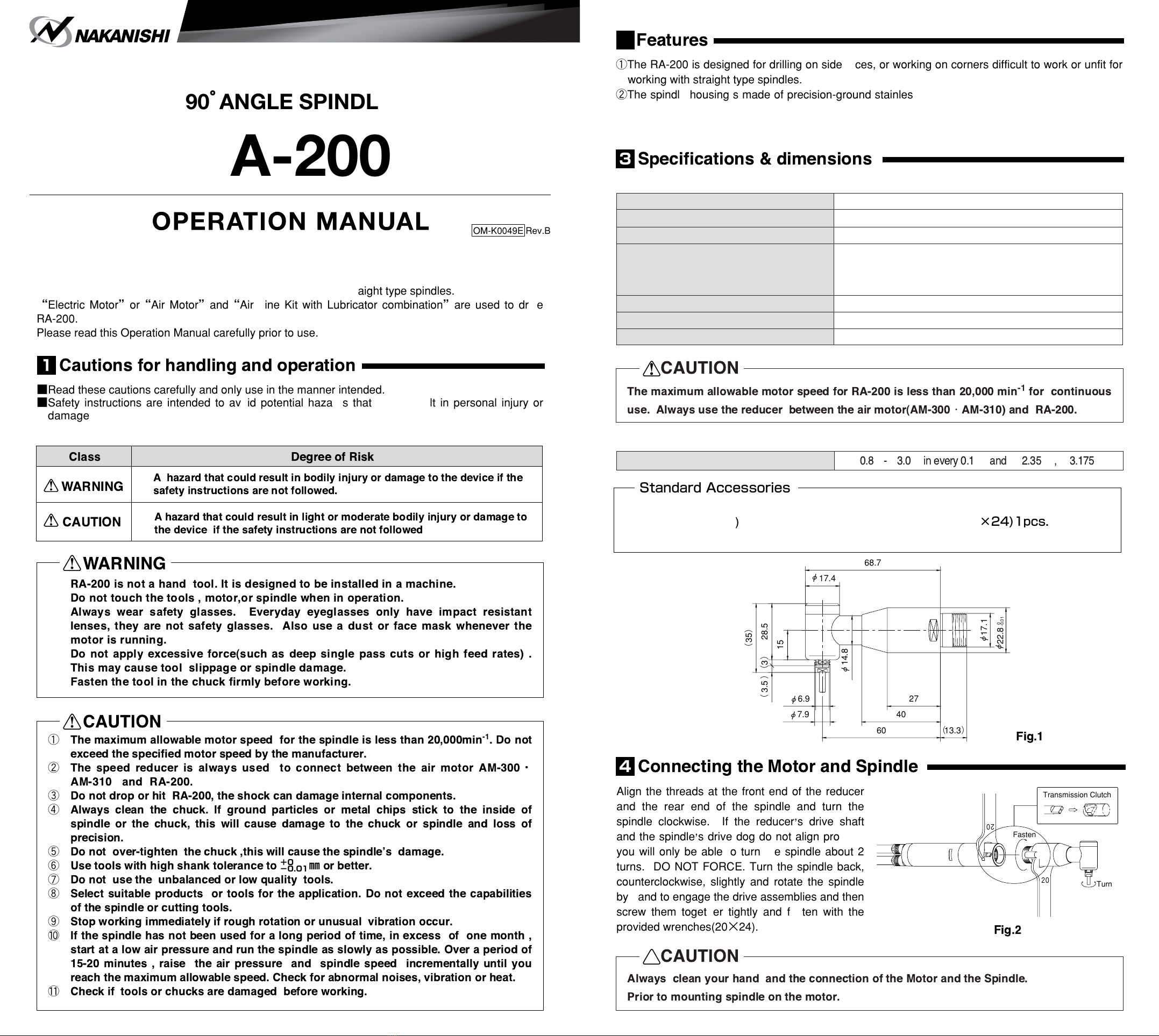
3-2Dimensions
3-1Specifications
Always clean your hand and the connection of the otor and the Spindle.
Prior to mounting spindle on the motor.
!
CAUTION
Colletchuck(CHS-□□)
φ
㎜
φ
㎜
㎜
φ
㎜
φ
㎜
〈Option〉
・ColletChuckφ3.0mm(provided)1pcs.
・Wrench(7×5.1
1pcs.
・Operationmanual
・Wrench(8×5)1pcs.
・Wrench(20×24)1pcs.
StandardAccessories
Fig.1
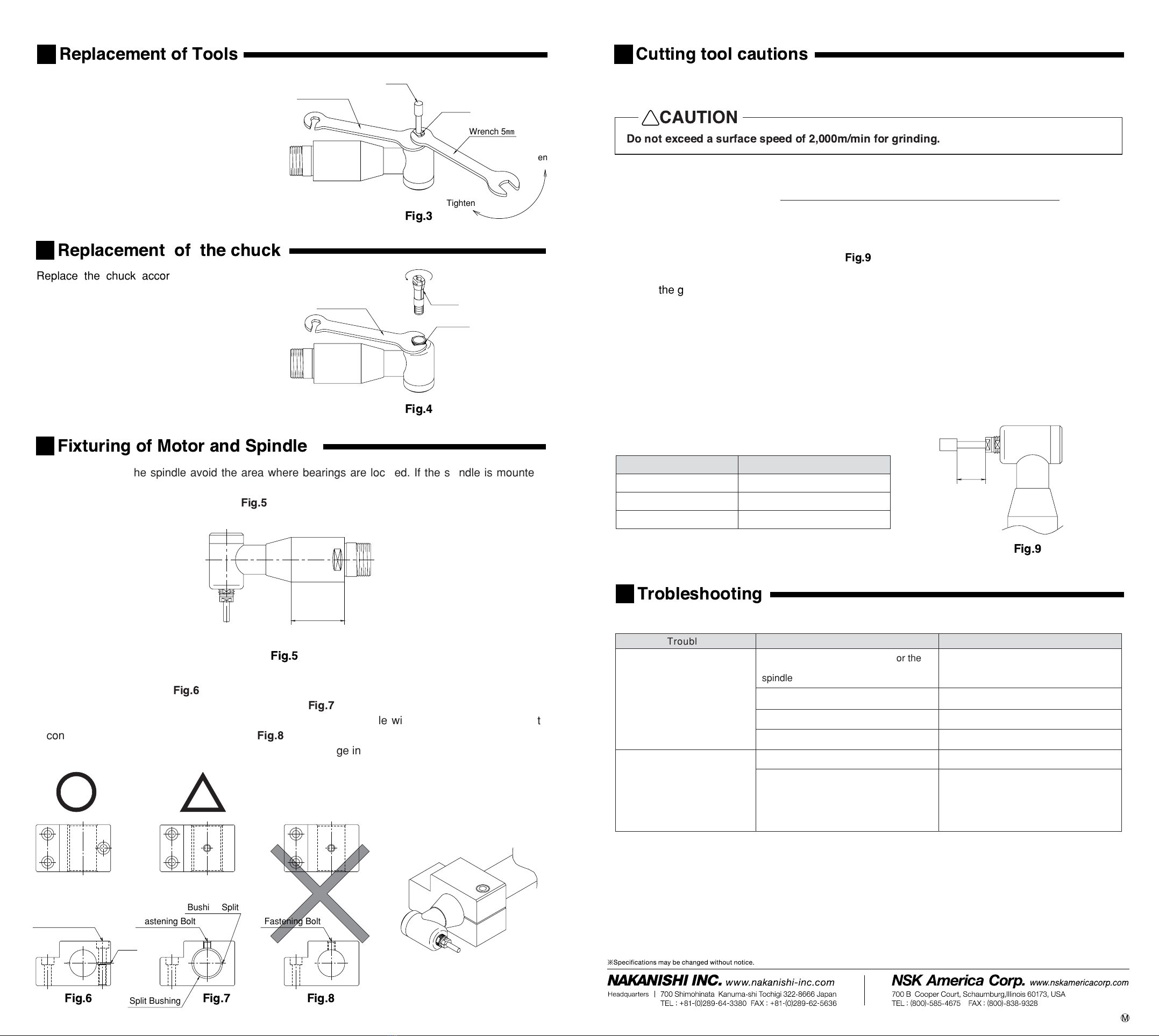
Alignthethreadsatthefrontendofthereducer
and the rear end of the spindle and turn the
spindle clockwise. If the reducer,s drive shaft
andthespindle,sdrivedogdonotalignproperly
youwillonlybeabletoturnthespindleabout2
turns.DONOTFORCE.Turnthespindleback,
counterclockwise, slightly and rotate the spindle
byhandtoengagethedriveassembliesandthen
screw them together tightly and fasten with the
providedwrenches(20×24).
4
Connecting the otor and Spindle
Fig.2
3
Specifications & dimensions
90°ANGLE SPINDLE
RA-200
OM-K0049E Rev.B
68.7
)35(
7.9φ 40
27
15
17.4
φ
14.8
φ
6.9φ
60 (13.3)
28.5)3()3.5(
-0.01
0
22.8
φ
17.1
φ
20
20
Turn
Fasten
TransmissionClutch