Nakanishi NR33-6000ATC-ESD User manual

1
OPERATION MANUAL
NR33 - 6000ATC - ESD
Automatic Tool Replacement Spindle
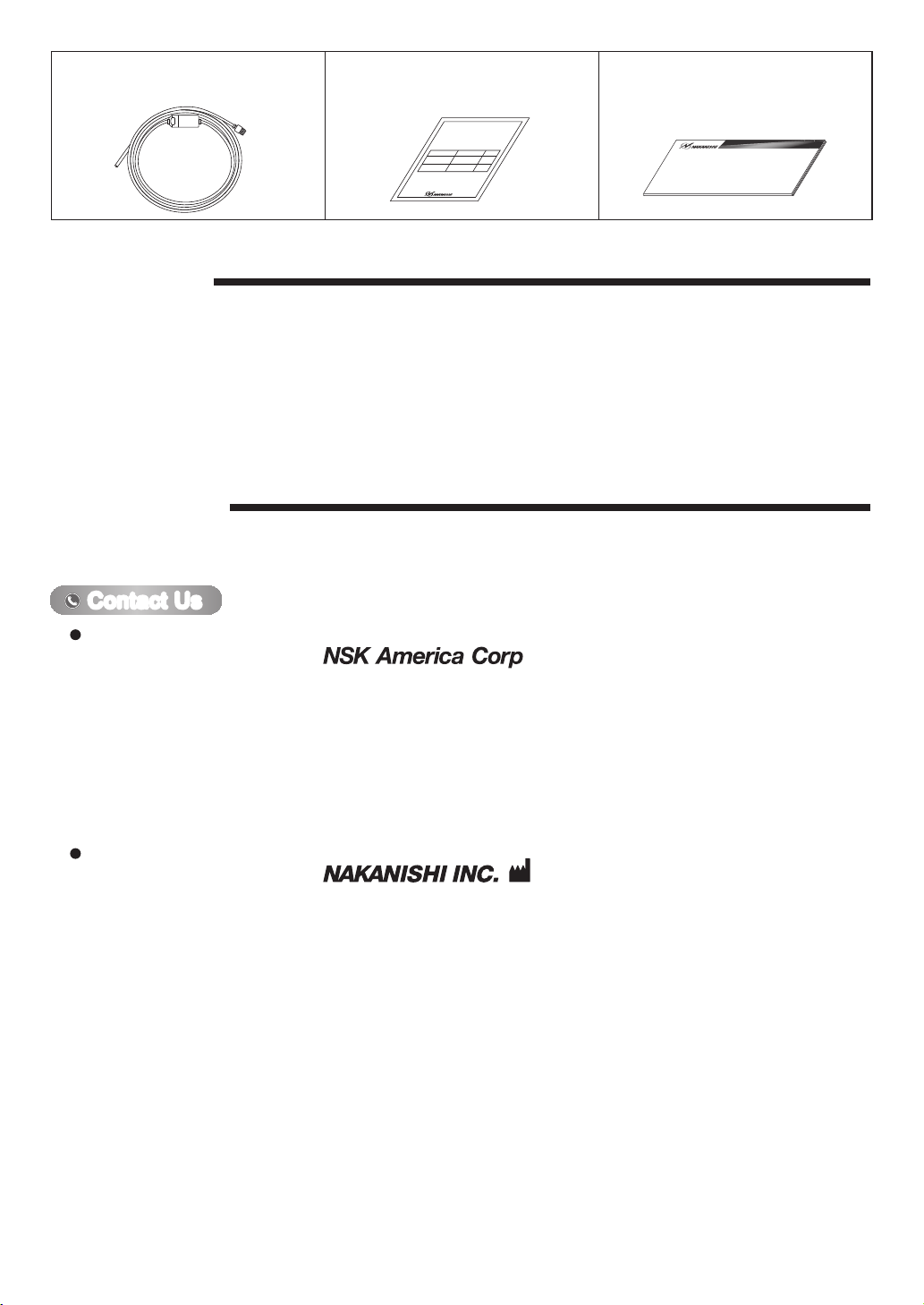
Thank you for purchasing the Automatic Tool Replacement Spindle " NR33-6000ATC-ESD ". This Spindle is
designed for cutting and separating PCB. The E3000 CONTROLLER, Brushless Motor and Air Line Kit are required
to drive this Spindle. Read this and all the associated component Operation Manuals carefully before use. Always
keep this Operation Manual in a place where a user can referred to for reference at any time.
000
1. CAUTIONS FOR HANDLING AND OPERATION
■Read these warnings and cautions carefully and only use in the manner intended.
■These warnings and cautions are intended to avoid potential hazards that could result in personal injury to the
operator or damage to the device. These are classified as follows in accordance with the seriousness of the risk.
Class Degree of Risk
WARNING A safety hazard could result in bodily injury or damage to the device if
the safety instructions are not properly followed.
CAUTION A hazard that could result in light or moderate bodily injury or damage
to the device if the safety instructions are not followed.
WARNING
①This Spindle is not a hand tool. It is designed to be used on CNC machines or special purpose
machines.
②Do not touch the cutting tool while it is running. It is very dangerous.
③Wear safety glasses, dust mask, and use a protective cover around the Spindle whenever the
Spindle is rotating.
④Never connect, disconnect or touch the Power Cord Plug or Motor Cord Plug with wet hands.
This may cause an electric shock.
⑤Never operate or handle the brushless motor and Spindle until you have thoroughly read the
Operation Manuals and safe operation has been confirmed.
1)To prevent injuries / damages, check the Spindle, brushless motor and cutting tool for
proper installation, before operating the Spindle and brushless motor.
2)Before disconnecting the Spindle and brushless motor, always turn the control power off
and turn the compressed air supply to the CONTROLLER off. Then it is safe to remove the
Spindle and brushless motor.
⑥Whenever installing a Spindle to a fixed metal base, ensure that the fixed metal base is
grounded in order to avoid risk of an electric shock.
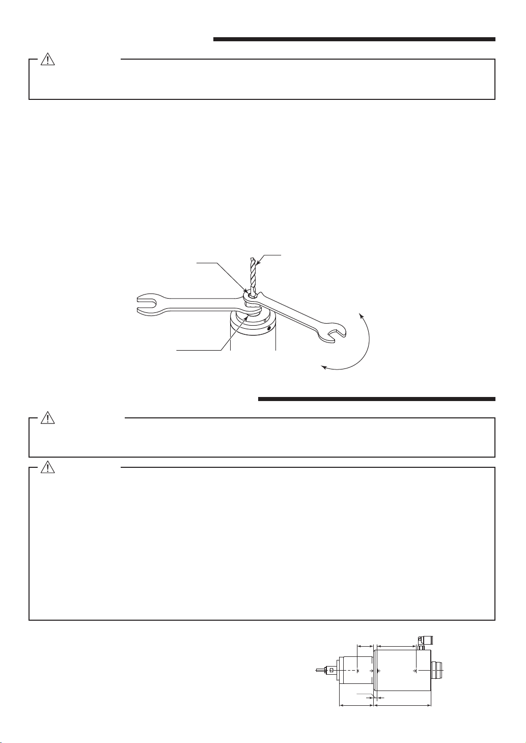
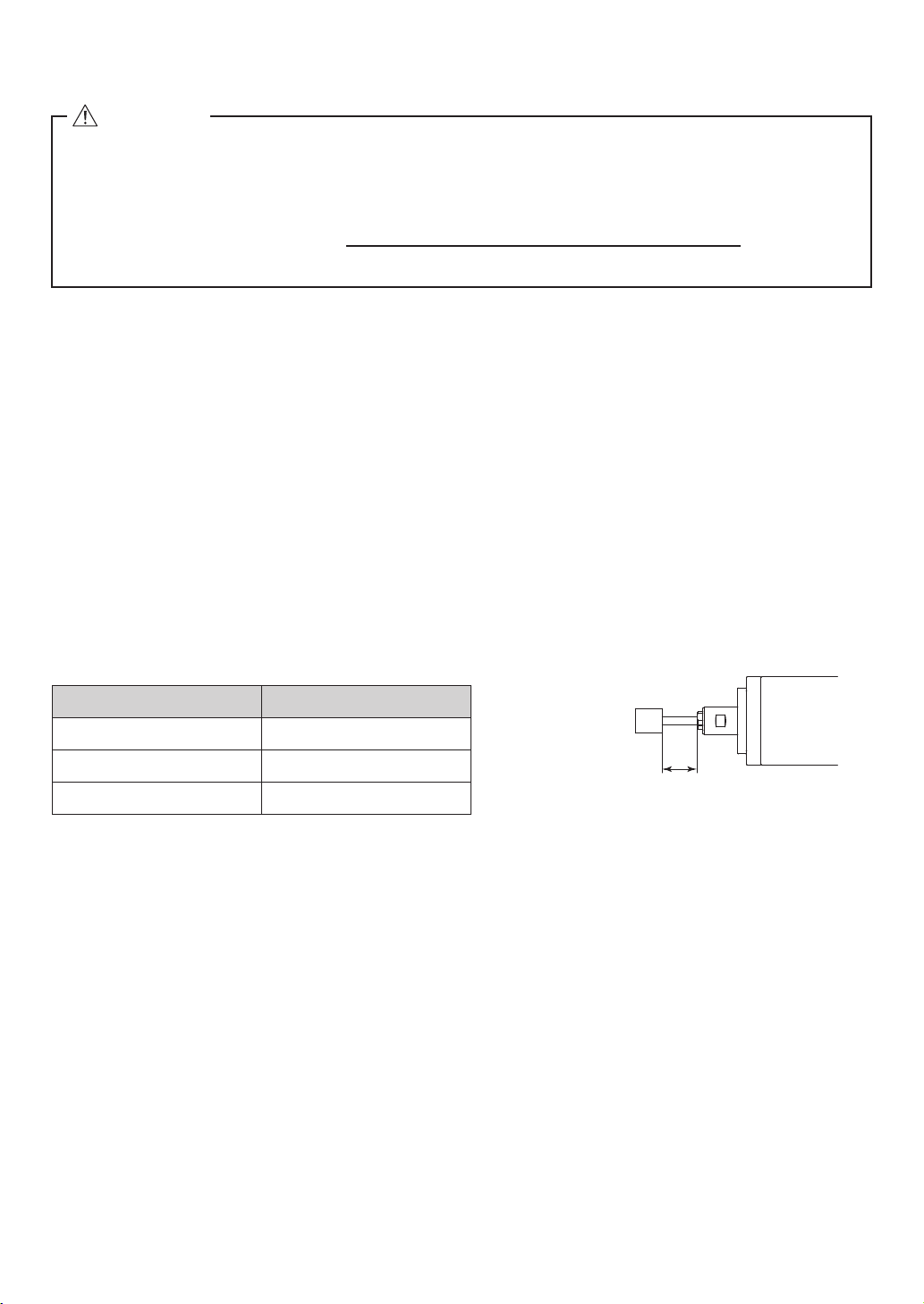
⑦When installing a tool, tighten the collet correctly and check again the collet before use. Do not
over-tighten the collet. This may cause damage to the Spindle.
⑧Do not open and close the collet while the brushless motor is runing.
⑨Do not use bent, broken, chipped, out of round or sub-standard tools, as this may cause them
to shatter or explode. Tools with fractures or a bent shank will cause injury to the operator.
When using a new tool, rotate it in a low speed and increase speed gradually for safety.
⑩Do not exceed the recommended maximum allowable speed of the tool. For your safety, use
speeds below the maximum allowable speed.
⑪Do not apply excessive force. This may cause injury to the operator by slippage or damage of
the tool, or loss of concentricity and precision of the Motor Spindle.
OM-KK0912EN
OM-KK0912EN000_NR33-6000ATC-ESD_200608_下版.indd 1 2020/06/05 16:47:51

2
CAUTION
①Do not drop or hit this Spindle, as shock can damage to the internal components.
②Do not connect this Spindle to the reduction gear. This may cause collet breakage by overload.
③Be sure to clean the collet, the inside of the spindle before replacing the tool. If ground
particles or metal chips stick to the inside of the spindle or the collet, damage to the collet or
spindle can occur due to the loss of precision.
④When cleaning a Spindle, stop the brushless motor and remove debris with a soft brush or a
cloth. Do not blow air into the End of Spindle Area (refer to section " 6 - 2 Outside View " ) with
compressed air as foreign particles or cutting debris may get into the ball bearing.
⑤Always clean the tool shank before installing the tool in the Spindle.
⑥
When sizing the correct collet size to the tool shank diameter, a tolerance of +0 〜- 0.01mm is
strongly recommended. A tool shank within the +0 〜- 0.1mm range is mountable, however,
using a tool other than recommended may cause poor concentricity and or insufficient tool
shank gripping force.
⑦Select suitable products or tools for all applications. Do not exceed the capabilities of the
Spindle or tools.
⑧Do not stop the supplied cooling air to the brushless motor during operation of the machine.
Removing the air pressure from the brushless motor causes a loss of purging, allowing the
Spindle to ingest coolant and debris. This will cause damage to the Spindle.
⑨Carefully direct coolant spray directly on the tool. Do not spray directly on the Spindle body.
If large amount spray directly on the Spindle, it may cause excess load of the Spindle rotation
with loss of durability to the Spindle.
⑩Stop working immediately when abnormal rotation or unusual vibration are observed.
Immediately, please check the content of section " 14. TROUBLESHOOTING".
⑪Always check if the tool and collet are damaged before and after operating.
⑫If the collet show signs of wear or damage, replace it before a malfunction or additional
damage occurs.
⑬After installation, repair, initial operation, or long periods of non operation, please refer to
section " 12. BREAK-IN PROCEDURE " detailed in Table. 2. When checking the spindle, no
vibration or unusual sound should be observed during rotation.
⑭Do not disassemble, modify or attempt to repair this Spindle. Additional damage will occur
to the internal components. Service must be performed by NSK NAKANISHI or an authorized
service center.
⑮When using this Spindle for mass production, please consider the purchase of an additional
Spindle to be used as a back-up in case of emergency.
2. BASIC PACKAGE
Table.1Packing List Contents
When opening the package, check if it includes all items listed in " Table.1 Packing List Contents ".
In the event of any shortage, please contact either NAKANISHI (see the " 4. CONTACT US " section) or your local dealer.
Spindle・・1pc.
NR33-6000ATC-ESD
Bar Wrench (K - 236)・・1pc.
Wrench (6.1 x 8)・・1pc.
Wrench (9 x 11)・・1pc.
11
9
6.1
8
OM-KK0912EN000_NR33-6000ATC-ESD_200608_下版.indd 2 2020/06/05 16:47:52

3
Air Hose with Filter
(φ6mm x 2m)・・1pc.
Inspection Card・・1pc. Operation Manual・・1set
Company Name
Business Hours
U.S. Toll Free No.
Telephone No.
Fax No.
Web Address
:
Industrial Div.
: 8:30am to 17:00pm (CST)
(closed Saturday, Sunday and Public Holidays)
: 800-585-4675
: 847-843-7664
: 847-843-7622
: www.nskamericacorp.com
Contact UsContact Us
For U.S. Market
Company Name
Business Hours
Telephone No.
Web Address
:
: 8:00am to 17:00pm
(closed Saturday, Sunday and Public Holidays)
: +81 (0) 289-64-3520
For Other Markets
4. CONTACT US
For your safety and convenience when purchasing our products, we welcome your questions.
If you have any questions about operation, maintenance and repair of the product, please contact us.
3. WARRANTY
We provide a limited warranty for our products. We will repair or replace the products if the cause of failure is due
to the following manufactures defects. Please contact us or your local distributor for details.
(1)Defect in manufacturing.
(2)Any shortage of components in the package.
(3)Where damaged components are found when initially opening the package.
(This shall not apply if the damage was caused by the negligence of a customer.)
検査成績表
Inspection Card
○○○○○○○○○○○
○○○○○○○○○
□□
○○○○
□□.
□□□□
□ □
□□□□□□□
□□□□□□
□□□□□□□
□□□□□□
□□□□□□□
□□□□
□□□□□□□
□□□□
□□□□□□
□ □ □
□□□
□□□
□□□□□□□□□□□□□□□□□□□□□□□□
□□□□□□□□□□□□□□□□□□□□□□□□
□□□□□
□□□□□□□□□□
□□□□□□□□□□□□□□□□□□□□□□□□
□□□□□□□□□□□□□□
□□□□□□□□□□
取扱説明書
OPERATION MANUAL
OM-KK0912EN000_NR33-6000ATC-ESD_200608_下版.indd 3 2020/06/05 16:47:53

4
5. FEATURES
①
The tools can be replaced automatically by putting ON - OFF the air.
②
Static electricity generated during operation can be released because the Spindle shaft and Spindle housing are
conductive.
③
The Spindle housing is made from precision ground, hardened, stainless steel (SUS).
Collet(CHB- □□)
φ
2.0mm,
φ
3.0mm,
φ
3.175mm,
φ
3.5mm,
φ
4.0mm
<Option>
6 - 1 Specifications
Model NR33-6000ATC-ESD
Maximum Motor Rotation Speed 60,000min-1 (rpm)
Spindle Accuracy Less than 1μm
Applicable Motor
*
This Spindle can not use the reduction gear
.
EM-3060, EM-3060J/EM-3060J-2M, EM-3030J/EM-3030J-2M
Milling Capacity
(Cutting or Milling PC boards with an end mill.)
End Mill Size
Work
Thickess
F
: Less than φ2.0mm
: PC board (ex. Glass Epoxy Resin)
: Less than 1.6mm
: Less than 3,000mm / min
Weight 1,170g
Noise Level at 1m distance Less than 70dB
6. SPECIFICATIONS AND DIMENSIONS
* You may need to lower feed rate (mm / min) depending on the shape of tools being used or the thickness of
work. Always check the milling condition before working.
6 - 2 Outside View
0
-0.01
φ24.5
φ10
φ33
0
-0.01
φ20.5
φ50
4−M5 x 0.8 depth10End of Spindle Area
(143.8)
112.5
41.7 70.8
(15)
(18.3) (13)
12.5
90°
45°
20
φ41
(Tool mounting depth)
30.2
Fig. 1
Temperature Humidity
Atmospheric Pressure
Operation Environment 0 - 40℃MAX.75%
(No condensation)800 - 1,060hPa
Transportation and Storage Environment -10 - 50℃10 - 85% 500 - 1,060hPa
OM-KK0912EN000_NR33-6000ATC-ESD_200608_下版.indd 4 2020/06/05 16:47:53

5
8. CONNECTION OF AIR HOSE AND AIR SUPPLY
①Connect the provided φ6mm Air Hose with Filter and 3-way valve to Air Inlet Joint shown in Fig. 3.
②Supply clean air from air compressor through air filter or air dryer to the 3-way valve at the set air pressure :
from 0.55 - 0.6MPa (79.8 - 87.0psi).
Fig. 3
〈When using the rear air inlet joint〉
φ6mm Air Hose with Filter
Air Inlet
Exhaust Air
Air Inlet Joint
3-way valve
7. CONNECTION OF THE SPINDLE TO THE BRUSHLESS MOTOR
Align the thread on the front end of the brushless motor and the rear
of the Spindle, and turn the Spindle clockwise. If the drive shaft of the
brushless motor does not engage properly to the drive dog on the
Spindle, DO NOT FORCE THEM TOGETHER. Loosen the Spindle
from the brushless motor, rotate the spindle shaft by hand then re-
try. The drive shaft and the drive dog must be fully engaged. When
fully engaged, secure the brushless motor and Spindle using the Bar
Wrench and 27mm wrench supplied with motor. (Fig. 2)
CAUTION
・Make sure your hands and all interlocking parts of
the brushless motor and Spindle are clean before
connecting the Spindle to the brushless motor. This is
critical in preventing contaminants from entering the
Spindle or the brushless motor.
・When connecting the Spindle to the brushless motor,
it is best to hold the brushless motor and Spindle in
a vertical position. Carefully connect by threading
the brushless motor on the Spindle and avoid mis-
alignment, as this will cause damage to the brushless
motor and or Spindle drive.
CAUTION
Securely connect the air hose to the brushless motor and air line kit to avoid accidental
disconnection and injury to the operator during use.
CAUTION
・The rear air inlet port is closed with an M5 screw before shipment. When changing the air inlet
port location, remove the M5 screw to install an air inlet joint.
・Use any one of the two air inlet port. Be sure to close the unused air inlet port with the removed
M5 screw.
・After installing the fitting, supply air and confirm that there is no air leakage, then proceed with
the installation.
27
Turn
Tighten
Transmission Clutch
Fig. 2
OM-KK0912EN000_NR33-6000ATC-ESD_200608_下版.indd 5 2020/06/05 16:47:54

6
・Please purchase the recommended commercially available air inlet fitting for the air inlet joint.
recommended air inlet
(With outside diameter of φ
9.9mm or less)
SMC is KQ2S04-M5G1. φ6mm to φ4mm tubing reducer SMC is KQ2H04-06A1.
・When installing the collet clamp / unclamp fittings, thoroughly read the instructions before connecting.(Fig. 4)
Fig. 4
3-way valve
Air Inlet Joint
φ4mm Air Hose
Reducer (φ6mm-φ4mm Adaptor)
φ6mm Air Hose with Filter
Air Inlet
Exhaust Air
9. CHANGING THE TOOL
①Stop the brushless motor and check that the motor is not rotating before replacement.
②Supply air pressure: from 0.55 - 0.6MPa (79.8 - 87.0psi) to Air Inlet Joint through 3-way valve. Then, the collet
will be opened.
At the same time, the tool is pushed out by the air exhaust for the coolant of brushless motor. So, need the tool
holder not to be damaged to the tool.
③Replace the tool.
④Exhaust the air through 3-way valve. The collet will be closed and the tool can be fixed.
WARNING
Do not open and close the collet while the brushless motor is running.
CAUTION
・When the air is supplied to the inlet joint of the Spindle, the tool will be pushed out by exhausting
the coolant air of brushless motor from the edge of Spindle. Be careful not to be damaged to the
tool or be injured.
・Use the air on-off valve through which the air can be exhausted. Do not use 2 way valve, because
the 2 way valve is not echausted and the collet is not closed.
・Do not open and close the collet before the tool is not installed. Because this will cause damage
to the collet or loss of precision.
RECOMMENDATION
Please set the cutting tools to minimize the overhang amount. 13mm is the maximum amount of
overhang to maintain high accuracy and safety.
OM-KK0912EN000_NR33-6000ATC-ESD_200608_下版.indd 6 2020/06/05 16:47:54

7
10. REPLACING THE COLLET
①Stop the coolant air of brushless motor.
②Supply air pressure : from 0.55 - 0.6MPa (79.8 - 87.0psi) to Air Inlet Joint to keep the collet opened.
Do not take off the tool when the air pressure is supplied.
③Place the provided 9mm wrench on the spindle shaft.
④Place the provided wrench 6.1mm on the collet and turn it counterclockwise to loosen the collet.
And take off the collet with the tool from the spindle shaft.
⑤Remove the tool from the collet.
⑥Insert the tool into another collet and turn it
clockwise to be attached on the spindle shaft.
⑦Tight it lightly with the provided wrench 9mm and wrench 6.1mm. (Specified tightening torque : 1.0 N・m).
⑧Exhaust the air through 3-way valve.
⑨After the collet is replaced, supply the coolant air of motor to the motor.
Fig. 5
Tighten
Loosen
Tool
Collet
9
11
6.1
Spindie Shaft
8
11. INSTALLATION OF THE SPINDLE
①When mounting a Spindle, refer to the Clamping Area
etched on the Spindle (Fig. 6).
WARNING
When installing a Spindle to a fixed base, make sure the fixed base is grounded in order to avoid
the risk of an electric shock.
CAUTION
・When installing a Spindle, do not hit, drop or cause shock to the Spindle. This may cause
damage to internal components and result in malfunctions.
・When installing the Spindle, be sure to secure within Clamping area etched on the Spindle O.D. If
the Spindle is installed incorrectly, amage to the internal components is possible.
・Cautions when tightening the securing bolts on to a Split Type Holder
Do not over-tighten the bolt. This will cause damage to Spindle's precision.
Tighten the bolt until the Spindle body can not be rotated by hand within the fixture.
Extreme tightening is not necessary or recommended.
Apply working force and check that the Spindle is tight before using.
・When installing a Spindle to a fixed base, make sure the fixed base (the material to be energized) is
grounded in order to avoid the risk of damage to electronic components of PCB due to static electricity
generated on the tool during rotation.
CAUTION
・Collet will be worn and torn if it will be opened and colsed about 5,000 - 10,000 times.
Replace it with the new collet at this time.
Fig. 6
70.8
(48)(20)
41.7
(4.5)
(Clamping area) (Clamping area)
CLAMPING AREA
CLAMPING
AREA
OM-KK0912EN000_NR33-6000ATC-ESD_200608_下版.indd 7 2020/06/05 16:47:55

8
③How to fabricate the Split Type Holder
(1)Rough bore the inside diameter of the
Split Type Holder.
(2)Cut a slit. (Ex. Slit 2mm) wide.
(3)Tighten the Screw for Removal and
Force Open the Slit Area.
(4)Insert a spacer (Ex. thickness = 2mm)
into the Slit Area.
(5)Loosen the Screw for Removal, and
tighten the fastening bolt with its
specified (recommended) torque.
(6)Finish the Split Type Holder so that the
inside diameter of the Split Type Holder
is φ33 / φ50 with its tolerance range
from
-
0.01mm to
-
0.015mm, and its
roundness and cylindricity of less than
5µm.
(7)When inserting the Spindle loosen the
Fastening Bolt, and tighten the Screw
for Removal, widening the Slit Area.
Screw for Removal
Fastening Bolt
Front View Side View
Fastening Bolt
Slit
Spacer
Fastening Bolt
Screw for Removal
Fig. 11
CAUTION
Do not allow set screws to come
directly in contact with the Spindle
body as shown in Fig. 9, as this
will result in damage to the Spindle
housing and internal components.
When installing, never clamp directly
over the bearings, as this will result in
bearing damage. (Refer to Fig. 10)
Fig. 10
Fastening Bolt
Deformation
Damage of internal
Components
Bearing
②When installing a Spindle to the holder, recommended installation method is shown Fig 7. Refer to " ③How to
fabricate the Split Type Holder ". If this is not possible, install as shown in Fig. 8.
Fig. 7
Fastening Bolt Fastening Bolt Fastening Bolt
Slit of Bushing
Slit
Spacer
Bushing with Slit
Split Type Holder
Fig. 8 Fig. 9
OM-KK0912EN000_NR33-6000ATC-ESD_200608_下版.indd 8 2020/06/05 16:47:56

9
12. BREAK-IN PROCEDURE
During transportation, storage or installation, the grease inside the bearings will settle. If the Spindle is suddenly run
at high-speed, the grease will be ejected from the bearings, causing excessive heat that will cause bearing damage.
After installation, repair, initial operation, or long periods of non operation, please follow the break-in procedure
detailed in Table. 2.
CAUTION
・How to confirm the correct tightening or clamping of the Spindles in the holder : In case of use
a brushless motor Measure the current value of the CONTROLLER's power cord by the clamp
meter.
Fasten the holder so that the increase in the no-load current value (during rotation at the
maximum rotation speed) with the Spindle fastened is 20mA (for type 120V) / 10mA (for type 200V
/ 230V) or less, compared to the no-load current value (during rotation at the maximum rotation
speed) without fastening the Spindle. Do not over-tighten the Fastening Bolt. It may damage
Spindle's precision and shorten the life of the bearings.
・The final responsibility for ensuring holder's safety for use in a given application is left to the
designer of the equipment in which NAKANISHI's Spindle is installed.
NAKANISHI offers Spindle with a wide variety of capabilities and specifications.
Please carefully check the Spindle's specifications against the requirements of your equipment
and verify suitability and safety of the Holder prior to initial use.
Steps 1 2 3 4 5
Rotation Speed (min-1) (rpm) 15,000 30,000 40,000 50,000 60,000
Rotation Time(min)15 10 10 10 15
Items to Check
No Abnormal
Noises
The spindle housing temperature during the break-
in process should not exceed 30 degrees C (54
degrees F) above ambient temperature. Should
the spindle exceed this limit, rest the spindle
for at least 20 minutes and re-start the break
in procedure from the beginning. If the housing
temperature rises again and exceeds 30 degrees
C (54 degrees F) above ambient temperature,
check the spindle and motor for proper installation.
The spindle
housing
temperature
during the
break-in
process should
not exceed
30 degrees C
(54 degrees F)
above ambient
temperature.
Table. 2
OM-KK0912EN000_NR33-6000ATC-ESD_200608_下版.indd 9 2020/06/05 16:47:56

10
Table. 3 Overhang and Speed
Overhang (mm) Max. Speed (min-1) (rpm)
20 N x 0.5
25 N x 0.3
50 N x 0.1
N=Max. Operating Speed with 13mm overhang. Fig. 12
13
13. CAUTIONS WHEN USING GRINDSTONES AND TOOLS
3.14 x Diameter (mm)x rotation speed (min-1) (rpm)
1,000 x 60
Surface Speed (m/s) =
CAUTION
The maximum surface speed or rpm is always specified for a grindstone. Do not exceed the
maximum speed with reference to the calculating chart below. Always follow the grindstone
manufacturer's recommendations.
①The proper surface speed for general grindstones is 10 - 30m/s.
②Do not exceed 13mm of overhang for mounted grindstones as shown in Fig. 12. If the overhang must
exceed 13mm, reduce the brushless motor speed in accordance with Table. 3.
③Dress the grindstone prior to use.
④Do not use cutting tools with bent or broken shanks, cracks or excessive run-out.
⑤For grinding, the maximum depth of cut should not exceed 0.01mm radially or axially. Reciprocate the tool
several times after each pass to eliminate tool pressure.
⑥Always operate cutting tools within the allowable recommended speed of the cutting tools. Use of a cutting
tool outside of the allowable speed of the cutting tools could cause damage to the Spindle and injury to the
operator.
⑦Keep the cutting tool shank and collet clean. If contaminants are left in the collet, excessive run-out will cause
damage to the cutting tool and or Spindle.
⑧Do not strike or disassemble the Spindle.
⑨Please set the cutting tools to minimize the overhang amount. 13mm is the maximum amount of overhang to
maintain high accuracy and safety.
OM-KK0912EN000_NR33-6000ATC-ESD_200608_下版.indd 10 2020/06/05 16:47:56

11
14. TROUBLESHOOTING
If a problem or concern occur, please check the following items prior to consulting your dealer.
15. DISPOSAL OF THE SPINDLE
When disposal of a Spindle is necessary, follow the instructions from your local government agency for proper
disposal of industrial components.
Trouble Cause Inspection/Corrective Action
Spindle does not rotate
or rotate smoothly.
The spindle ball bearings have
been damaged.
Replace the ball bearings.
(Return to NAKANISHI dealer service.)
The motor has been damaged. Replace the motor.
(Return to NAKANISHI dealer service.)
Overheating during
rotation.
Cutting debris has contaminated
the ball bearings, and the ball
bearings are damaged.
Replace the ball bearings.
(Return to NAKANISHI dealer service.)
Abnormal vibration or
noise during rotation.
The tool shank is bent. Replace the tool.
Cutting debris has contaminated
the ball bearing.
Replace the ball bearings.
(Return to NAKANISHI dealer service.)
The spindles ball bearings have
been damaged.
Tool slippage. Collet is not correctly installed. Check and clean the collet. Reinstall the collet.
The collet is worn. Replace the collet.
High run-out. The tool is bent. Change the tool.
Collet is not correctly installed. Secure the collet correctly.
The collet is worn. Replace the collet.
Inside of the Spindle is worn. Replace the Spindle shaft.
(Return to NAKANISHI dealer service.)
Contaminants inside the collet or
the Spindle.
Clean the collet and the inside of the taper and
Spindle.
The Spindle ball bearings have
been damaged.
Replace the ball bearings.
(Return to NAKANISHI dealer service.)
Check can not be opened
and closed.
Poor the air hose. Check all threaded joints and re-tighten if
necessary.
The air hose has been damaged. Replace the air hoses.
Low air pressure. Check and adjusting the air circuit.
Error connection of the air circuit.
Power can not be
supplied.
The conductive component is
worn.
Replace the conductive component.
(Return to NAKANISHI dealer service.)
Refer to the brushless motor and the E3000 CONTROLLER Operation Manuals.
OM-KK0912EN000_NR33-6000ATC-ESD_200608_下版.indd 11 2020/06/05 16:47:57

Contents are subject to change without notice.
2020.06.08 005 Ⓢ
OM-KK0912EN000_NR33-6000ATC-ESD_200608_下版.indd 12 2020/06/05 16:47:57
Table of contents
Other Nakanishi Tools manuals