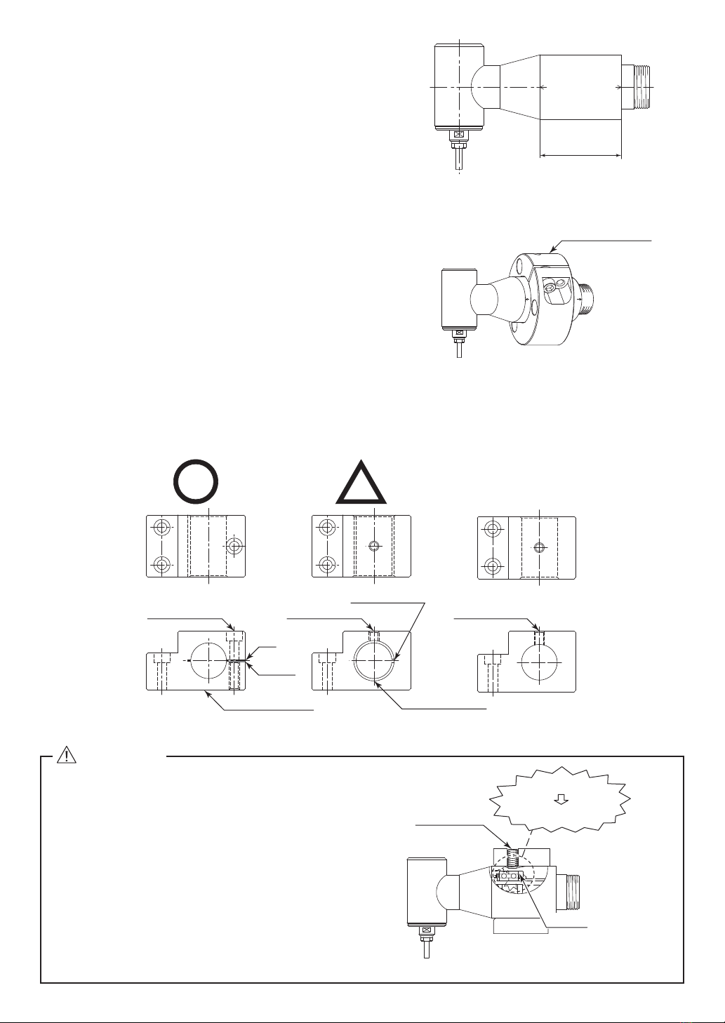
Nakanishi RA-151E User manual

1
RA - 151E
90°Angle Spindle
Thank you for purchasing 90°Angle Spindle " RA - 151E ". This Spindle is designed for grinding, small diameter
drilling and milling, etc. The E3000 CONTROLLER, Brushless Motor or Air Motor and Air Line Kit are rquired to
drive this Spindle. Read this and all the associated component Operation Manuals carefully before use. Always
keep this Operation Manual in a place where a user can referred to for reference at any time.
OPERATION MANUAL OM-K0422E 001
1. CAUTIONS FOR HANDLING AND OPERATION
■Read these warnings and cautions carefully and only use in the manner intended.
■These warnings and cautions are intended to avoid potential hazards that could result in personal injury to the
operator or damage to the device. These are classified as follows in accordance with the seriousness of the risk.
Class Degree of Risk
WARNING
A safety hazard could result in bodily injury or damage to the device if the
safety instructions are not properly followed.
CAUTION A hazard that could result in light or moderate bodily injury or damage
to the device if the safety instructions are not followed.
WARNING
①This Spindle is not a hand tool. It is designed to be used on CNC machines or special purpose
machines.
②Do not touch the cutting tool while it is running. It is very dangerous.
③Wear safety glasses, dust mask, and use a protective cover around the Spindle whenever the
Spindle is rotating.
④Never connect, disconnect or touch the Power Cord Plug or Motor Cord Plug with wet hands.
This may cause an electric shock.
⑤Never operate or handle the motor and Spindle until you have thoroughly read the Operation
Manuals and safe operation has been confirmed.
1) To prevent injuries / damages, check the motor, Spindle and cutting tool for proper
installation, before operating the motor and Spindle.
2) Before disconnecting the motor and Spindle, always turn the control power off and turn the
compressed air supply to the CONTROLLER off. Then it is safe to remove the motor and
Spindle.
⑥When installing a Spindle to a fixed base, make sure the fixed base is grounded in order to
avoid the risk of an electric shock.
⑦When installing a tool, tighten the collet chuck correctly and check again the collet chuck
before use. Do not over-tighten the collet chuck. This may cause damage to the Spindle.
⑧Do not use bent, broken, chipped, out of round or sub-standard tools, as this may cause them
to shatter or explode. Tools with fractures or a bent shank will cause injury to the operator.
When using a new tool, rotate it in a low speed and increase speed gradually for safety.
⑨Do not exceed the maximum recommended allowable tool speed. For your safety, use speeds
below the maximum allowable speed.
⑩Do not apply excessive force. This may cause tool slippage, tool damage, injury to the operator
or loss of concentricity and precision.

2
Model RA - 151E
Maximum rotating
speed at the tool
For Air Motor
7,200min-1 (rpm)
For Brushless Motor
7,490min-1 (rpm)
Maximun Motor
Rotation Speed
For Air Motor
19,000min-1 (rpm)
For Brushless Motor
20,000min-1 (rpm)
Applicable Motor
For Air Motor
AM - 3020R / L, AM - 3020RA / LA
For Brushless Motor
EM - 3060, EM - 3060J, EM - 3060J - 2M, EM - 3030J,
EM - 3030J - 2M
Reduction Ratio 1 / 2.67
Standard Collet Chuck (CH8 - 3.0) ȭ3.0mm
Weight 385g
3 - 1 Specifications
3. SPECIFICATIONS AND DIMENSIONS
①Do not exceed the maximum allowable motor speed of 20,000min-1 (rpm).
②Do not drop or hit this spindle, as shock can damage to the internal components.
③Be sure to clean the collet chuck, the inside of the Spindle before replacing the tool. If ground
particles or metal chips stick to the inside of Spindle or the collet chuck, damage to the collet
chuck or Spindle can occur due to the loss of precision.
④When cleaning a Spindle, stop the motor and remove debris with a soft brush or a cloth. Do
not blow air into the Spindle with compressed air as foreign particles or cutting debris may
get into the ball bearing.
⑤Always clean the tool shank before installing the tool in the Spindle.
⑥
When sizing the correct collet chuck size to the tool shank diameter, a tolerance of + 0 〜
-
0.01mm
is strongly recommended. A tool shank within the + 0 〜
-
0.1mm range is mountable, however,
this may cause poor concentricity and or insufficient tool shank gripping force.
⑦Select suitable products or tools for all applications. Do not exceed the capabilities of the
Spindle or tools.
⑧During supply of coolant spray, do not stop the supply air pressure.
If stop the supply air pressure, entering coolant spray to internal Air Turbine Spindle by lost
air purge. This may occur damage to the Air Turbine Spindle.
⑨Carefully direct coolant spray to the tool. Do not spray directly on the Spindle body.
⑩Stop working immediately when abnormal rotation or unusual vibration are observed.
Immediately, please check the content of section " 10. TROUBLESHOOTING ".
⑪Always check if the tool, collet chuck are damaged before and after operating.
⑫If the collet chuck show signs of wear or damage, replace it before a malfunction or additional
damage occurs.
⑬After installation, repair, initial operation, or long periods of non operation, please refer to
section " 8. BREAK-IN PROCEDURE " detailed in Table 1. When checking the Spindle, no
vibration or unusual sound should be observed during rotation.
⑭Do not disassemble, modify or attempt to repair this Spindle. Additional damage will occur
to the internal components. Service must be performed by NSK NAKANISHI or an authorized
service center.
⑮When using this Spindle for mass production, please consider the purchase of an additional
Spindle to be used as a back-up in case of emergency.
CAUTION
2. FEATURES
①
The RA - 151E is capable of working on corners difficult to work or unfit for working with straight type Spindle.
②The Spindle housing is made from precision ground, hardened, stainless steel (SUS) with an outside diameter
of ȭ30mm.
③Various sizes of collet chucks are available CH8 0.8mm - 3.0 mm. Standard collet chuck is CH8 3.0mm or CH8
3.175mm. (For U.S. market CH8 3.175mm.)

3
Fig. 1
37.5
(3.2)
75.2 (13)
20
40.15
-0.01
0
ȭ30
ȭ22.8
ȭ9.0
3 - 2 Outside View
Turn
Tighten
Transmission Clutch
27
27
Fig. 2
CAUTION
Use less than the maximum allowable motor speed 20,000min-1 (rpm).
DO NOT exceed the maximun allowable motor speed 20,000min-1 (rpm) for the Spindle.
Standard Accessories
・Collet Chuck ȭ3.0mm (CH8 - 3.0) or ȭ3.175mm (CH8 - 3.175 ) ・・・ 1pc.
(For U.S. market ȭ3.175mm (CH8 - 3.175))
・Wrench (7 ×5.5) ・・1pc.
・Wrench (8 ×5)・・1pc.
・Wrench (22 ×27)・・1pc.
・Operation Manual・・1set.
Collet Chuck (CH8 - □□ )ȭ0.8mm 〜ȭ3.0mm in 0.1mm increments and ȭ2.35mm, ȭ3.175mm
< Option > * The collet chuck is attached to the Spindle.
Align the thread on the front end of the motor and the rear of the Spindle, and turn the Spindle clockwise. If the
drive shaft of the motor does not engage properly to the drive dog on the Spindle, it may only turn aprroximately
two threads before stopping. DO NOT FORCE THEM TOGETHER. Loosen the Spindle from the motor, rotate the
Spindle shaft by hand then re-try. The drive shaft and the drive dog must be fully engaged. When fully engaged,
secure the motor and Spindle using the provided 27mm wrench (Fig. 2).
4. CONNECTION OF THE SPINDLE TO THE MOTOR
CAUTION
Make sure your hands and all interlocking parts of the Spindle and motor are clean before
connecting the motor to the Spindle. This is critical in preventing contaminants from entering the
motor or Spindle.

7. INSTALLATION OF THE SPINDLE
WARNING
When installing a Spindle to a fixed base, make sure the fixed base is grounded in order to avoid
the risk of an electric shock.
CAUTION
・When installing a Spindle, do not hit, drop or cause shock to the Spindle. This may cause
damage to internal components and result in malfunctions.
・When mounting the Spindle, be sure to mounting within clamping area etched on the Spindle.
If the Spindle is installed incorrectly, this will cause and damage to the Spindle.
・Cautions when tightening the securing bolt of the Split Type Holder
Do not over-tighten the bolt. This may cause damage to Spindle's precision.
Tighten the bolt until the Spindle body can not be turned by hand within the fixture.
Extreme tightening is not necessary or recommended.
Apply working force and check that the Spindle is tight before using.
4
Fig. 3
8
5
Spindle Shaft
7
5.5
Loosen
Tighten
Wrench 5.5mm
Tool
Collet Chuck
Wrench 8mm
①Set the provided 8mm wrench on the
Spindle.
②Place the provided 5.5mm wrench on the
chuck and turn it counter-clockwise to loosen
the collet chuck and remove the tool.
③Clean the collet chuck, then insert the new
tool and tighten the collet chuck by turning
clockwise. Do not overtighten.
Fig. 4
8
5
Loosen
Collet Chuck
Wrench 8mm
Spindle Shaft
①Remove the tool according to the section
" 5. CHANGING THE TOOL " procedure
above (Fig. 3).
②Place the provided 8mm wrench on the spindle
shaft, and turn the top of the collet chuck
counter-clockwise to remove the collet chuck
(Fig. 4).
③Install the new collet chuck into the Spindle
by turning it clockwise.
RECOMMENDATION
Please minimize the tool overhang
amount to maintaining high accuracy.
5. CHANGING THE TOOL
CAUTION
Do not tighten the collet chuck without inserting a tool or dummy bur as this will result in damage
to the collet chuck.
6. REPLACING THE COLLET CHUCK

①When mounting a Spindle, refer to the Clamping Area
etched on the Spindle (Fig. 5).
37.5
(Clamping Area)
CLAMPING AREA
Fig. 5
②When installing a Spindle to the holder, recommended installation method is shown Fig. 7. Refer to " ③How to
fabricate the Split Type Holder.
If this is not possible, install as shown in Fig. 8.
Fastening Bolt
Slit of Bushing
Fastening Bolt Fastening Bolt
Bushing with Slit
Split Type Holder
Slit
Spacer
Fig. 7 Fig. 8 Fig. 9
CLAMPING AREA
Grip Ring GR-30
(Sold Separately)
Fig. 6
* When installing a Spindle, use a " Grip Ring GR - 30
(sold separately) " (Fig. 6) recommended. If the Grip
Ring GR - 30 (sold separately) cannot be used due to
the restriction of dimension and space, install as shown
in ②below.
Do not allow set screws to come directly in
contact with the Spindle body as shown in Fig.
9, as this will result in damage to the Spindle
housing and internal components.
When installing, never clamp directly over the
bearings, as this will result in bearing damage.
(Refer to Fig. 10)
Fastenig Bolt
Deformation
Damage of internal
Components
Bearing
Fig. 10
CAUTION
5

CAUTION
・How to confirm the correct tightening or clamping of the Spindles in the holder : In case of use
a brushless motor.
Measure the current value of the CONTROLLER's power cord by the clamp meter.
Fasten the holder so that the increase in the no-load current value (during rotation at the
maximum rotation speed) with the Spindle fastened is 10mA (for type 200V / 230V) or less,
compared to the no-load current value (during rotation at the maximum rotation speed)
without fastening the Spindle. Do not over-tighten the Fastening Bolt. It may damage Spindle's
precision and shorten the life of the bearings.
・The final responsibility for ensuring holder's safety for use in a given application is left to the
designer of the equipment in which NAKANISHI's Spindle is installed.
NAKANISHI offers Spindles with a wide variety of capabilities and specifications.
Please carefully check the Spindle's specifications against the requirements of your equipment
and verify suitability and safety of the Holder prior to initial use.
6
③How to fabricate the Split Type Holder
(1) Rough bore the inside diameter of the Split
Type Holder.
(2) Cut a slit. (Ex. Slit 2mm) wide
(3) Tighten the Screw for Removal and Force
Open the Slit Area.
(4) Insert a spacer (Ex. thickness = 2mm) into
the Slit Area.
(5) Loosen the Screw for Removal, and tighten
the fastening bolt with the specified torque.
(6) Finish the Split Type Holder so that the
inside diameter of the Split Type Holder is
ȭ30 with its tolerance range from
-
0.01mm
to
-
0.015mm, and its roundness and
cylindricity of less than 5μm.
(7) When inserting the Spindle loosen the
Fastening Bolt and twist the Screw for
Removal, and widen the Slit Area.
Front View
Fastening Bolt
Slit
Side View
Fastening Bolt
Screw for Removal
Spacer
Fastening Bolt
Spacer
Screw for Removal
Spacer
Fig. 11
Steps
12 3 4
Air Pressure (MPa) For Air Motor
0.1 0.2 0.3 0.4
Rotation Speed (min-1) (rpm)
For Brushless Motor
5,000 10,000 15,000 20,000
Rotation Time (min)
15 10 10 15
Items to Check
No Abnormal
Noises.
The Spindle housing temperature during
the break-in process should not exceed
20 degrees C (36 degrees F) above
ambient temperature. Should the Spindle
exceed this limit, rest the Spindle for at
least 20 minutes and re-start the break
in procedure from the beginning. If the
housing temperature rises again and
exceeds 20 degrees C (36 degrees F)
above ambient temperature, check the
Spindle and motor for proper installation.
The Spindle
housing
temperature
during the break-
in process should
not exceed
20 degrees C
(36 degrees F)
above ambient
temperature.
Table 1.
8. BREAK-IN PROCEDURE
During transportation, storage or installation, the grease inside the bearings will settle. If the Spindle is suddenly run at
high-speed, the grease will be ejected from the bearings, causing excessive heat that will cause bearing damage. After
installation, repair, initial operation, or long periods of non operation, please follow the break-in procedure detailed in Table 1.

7
①The proper surface speed for general grindstones is 10 - 30m / s.
②Do not exceed 13mm of overhang for mounted grindstones as shown in Fig. 12. If the overhang must exceed
13mm, reduce the motor speed in accordance with Table 2.
③Dress the grindstone prior to use.
④Do not use cutting tools with bent or broken shanks, cracks or excessive run-out.
⑤For grinding, the maximum depth of cut should not exceed 0.01mm radially or axially. Reciprocate the tool
several times after each pass to eliminate tool pressure.
⑥Always operate cutting tools within the allowable recommended speed of the cutting tools. Use of a cutting
tool outside of the allowable speed of the cutting tools could cause damage to the spindle and injury to the
operator.
⑦Keep the cutting tool shank and collet chuck clean. If contaminants are left in the collet chuck or chuck nut,
excessive run-out will cause damage to the cutting tool and or Spindle.
⑧Do not strike or disassemble the Spindle.
⑨Please minimize the tool overhang amount to maintaining high accuracy. 13mm is the maximum amount of
overhang to maintain high accuracy and safety.
3.14 x Diameter (mm) x rotation speed (min-1) (rpm)
1,000 x 60
Surface Speed (m/s)
=
9. CAUTIONS WHEN USING GRINDSTONES AND TOOLS
CAUTION
The maximum surface speed or rpm is always specified for a grindstone. Do not exceed the
maximum speed with reference to the calculating chart below. Always follow the grindstone
manufacturer's recommendations.
Fig. 12
13
Table 2. Overhang and Speed
Overhang (mm) Max. Speed (min-1) (rpm)
20 N x 0.5
25 N x 0.3
50 N x 0.1
※N = Max. Operating Speed with 13mm overhang.

2014.05.20 0001 ה
Trouble Cause Inspection / Corrective Action
Spindle does not
rotate or rotate
smoothly.
The Spindles ball bearings have
been damaged.
Replace the ball bearings.
(Return to NAKANISHI dealer service.)
The motor has been damaged. Replace the motor.
(Return to NAKANISHI dealer service.)
Overheating during
rotation.
Cutting debris has contaminated
the ball bearings, and the ball
bearings are damaged.
Replace the ball bearings.
(Return to NAKANISHI dealer service.)
Abnormal vibration
or noise during
rotation.
The tool shank is bent. Replace the tool.
Cutting debris has contaminated
the ball bearing.
Replace the ball bearings.
(Return to NAKANISHI dealer service.)
The Spindles ball bearings have
been damaged.
Tool slippage. Collet chuck is not correctly
installed.
Check and clean the collet chuck. Reinstall the collet
chuck.
The collet chuck is worn. Replace the collet chuck.
High run-out. The tool is bent. Change the tool.
Collet chuck is not correctly
installed.
Secure the collet chuck correctly.
The collet chuck is worn. Replace the collet chuck.
Inside of the Spindle is worn. Replace the Spindle shaft.
(Return to NAKANISHI dealer service.)
Contaminants inside the collet
chuck or the Spindle.
Clean the collet chuck and the inside of the taper and
Spindle.
The Spindle ball bearings has
been damaged.
Replace the ball bearings.
(Return to NAKANISHI dealer service.)
10. TROUBLESHOOTING
If a problem or concern occur, please check the following items prior to consulting your dealer.
11. DISPOSAL OF THE SPINDLE
When disposal of a Spindle is necessary, follow the instructions from your local government agency for proper
disposal of industrial components.
In case of using a Brushless Motor, refer to Brushless Motor and E3000 CONTROLLER Operation Manuals.
Table of contents
Other Nakanishi Tools manuals