NAKTO Pony User manual

Pony

Fully Assembled Pony White and Pony Red.
Pony White
Pony Red

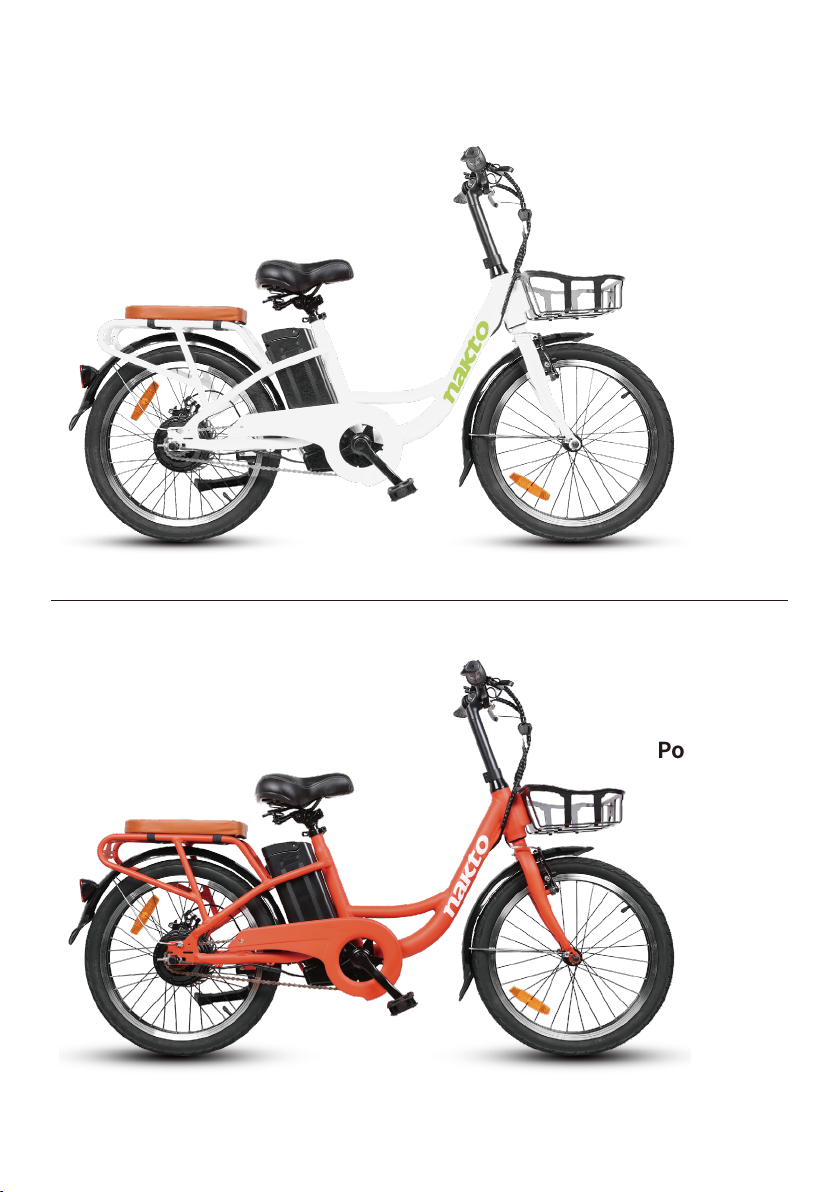
Let’s start assembling your Pony ebike!
(Please read this entire assembly manual before assembly as it will save
you a lot of time!)
Step One: Unpack the ebike.
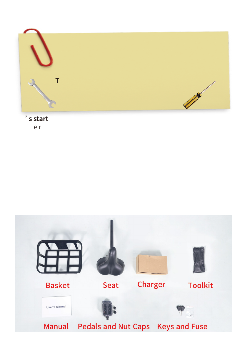
1.Pull the frame and all parts (charger, seat, tookit, keys & fuse, manual,
bolt caps, rear cushion, basket and pedals) out of cardboard box. Sepa-
rate bike from foam padding. Cut off all zip ties with scissors while being
extra careful as not to damage the paint or cut any wires or cables.
Notice: The fuse is not used for assembly. Keep it in a safe place that it
will be used for the replacement if the original fuse were damaged.
Ensure all the following pieces are included with the Nakto Pony.
Assembly Instructions: Pony
Tools included: Screwdriver, Phillips & Slotted 2 in 1
Double open-end wrench, 13mm/15mm
Allen wrench, 5mm
Allen wrench, 6mm
Tools needed: Scissor
Bike pump

2.Now stand the bike upright. Place some foam padding under the front
fork if placed on the ground or put it on bike assembly/repair stand if you
have one. We want to keep your bike looking new!
Step Two: Assemble the front wheel.
1.Loosen axle nuts on front wheel to make room for the front fork.
2.Remove the brake cable from the linkage of the left arm while squeez-
ing the brake arms to make room for the front wheel.

3.Lift the front of the bike and lower the fork onto the wheel. Notice: The
axle should enter the fork dropouts fully.
4.Line up the axle lock washers (These are the metal washer with a bent
tab on one side) with the hole at each fork. Notice: These two special
fork lock washers keep the wheel from falling off if the axle nuts ever
loosen up! Tighten the axle nuts by hand.
5.Once the lock washers are in place tighten both axle nuts with the
supplied double open-end wrench. Notice: Before doing the final tight-
ening of the axle nuts make sure the wheel is square and true with the
forks.

6.Push the black plastic caps onto the axle nuts.
7.Put the brake cable back to the linkage of the left arm while squeezing
the brake arms.

Step Three: Install the handlebar.
1.Insert the handlebar stem into the clamp.
2.Install the handlebar stem together with clamp onto the steer stem.

5.Tighten the bolt at the clamp with the supplied allen wrench.
3.Set the stem to the desired height but not exceed max height or mini-
mum insertion.
4.Align the stem so the handlebar is perpendicular to the front wheel.

6.Perform a twist test.
(1).Brace the front wheel between your legs.
(2).Switch hands so the opposite hands are pushing and pulling with
about 20 pounds of force make sure the handlebar and front wheel are
still properly aligned.
(3).Repeat the twist test pulling/pushing with the opposite hands.

Step Four: Install the front fender.
1.Remove the fender mounting bolt from the fork arch with the supplied
screwdriver and set aside.
2.Place the fender in position. From the back of the front tire, pass the
front fender mounting point under the front fork arch.
3.Attach fender to the fork arch. Pass the bolt through the fender mount-
ing point and fork arch mounting point. Thread the locknut at the bolt
end and tighten with the supplied screwdriver.

4.Attach the fender mounting arms to the front fork. Remove the mount-
ing bolts from the fork. Pass the bolt through the arm mount and fork
mounting point. Ensure the fender is centered and tighten both the
mounting bolts.
Step Five: Adjust the front brake system.
NOTICE: The adjustment of the front brake system is not easy. The
following steps are only a general guide. If you are not sure you have the
experience, skills, and tools to correctly perform all steps, consult a
certified, reputable bike mechanic to assist with it.
1.Pad Adjustment.
Remove the brake cable from the linkage of the left arm while squeezing
the brake arms.
Loose the pad mount, bring the arm and pad to the rim, and adjust.
Locate the pad to the top edge of the braking surface. Note: Do not locate
the pad to the top edge of the rim. It would hit the tire.
Bring the pad gently to the rim and push with some mild force and secure
the nut. The pad will tend to be self-aligning and put the convex-concave
washers where it needs to be correctly aligned with two flat surfaces, the
rim and the pad-aligned. Hold the pad as you tighten the final tightness.
Repeat the process on the other side.
Put the brake cable back to the linkage of the left arm while squeezing
the brake arms.

2.Cable Attachment.
Before we draw the pads together, back out the barrel adjusters three or
four turns. So that we can have some fine tuning at the lever.
Loosen the pinch bolt. Pull the arms together with your hand and pull
the cable out with some mild force. It is only necessary to get the rim
close. Then secure the pinch bolt. It should flatten and crush the cable.

3.Set Pad Clearance.
Bring the barrel adjuster in toward the lever, giving more slack. Typically,
the pads should feel like they are contacting the rotor at a minimum of
1/2 the lever travel.

4.Centering.
Centering is done by subtle changes in spring tension. There are screws
to the return spring on both sides. By tightening the screw, you are
increasing tension on whatever side you tighten. The end goal here is to
keep even pad clearance on either side of the rim. Take the right pad for
example, we can tighten to make it far from the rim, or loosen the screw
to make it close.

Step Six: Install the seat.
1.Open the quick release lever by hinging it open fully.
2.Insert seat post into seat tube. Adjust the seat post up or down to a
comfortable height, while ensuring the seat post is inserted into the
frame past the minimum insertion point.
3.Close the quick release lever to secure the seat post and check that it
cannot move. If needed, use the thumb nut to add tension to the clamp
so there is some resistance when the lever is in line with the clamp bolt.

Step Seven: Install the pedals.
1. Locate the pedal with an “R” stamped into the end of the pedal axle,
which indicate it is the right pedal. The right pedal goes on the crank on
the right side of the bike. The remaining pedal with an “L” stamped into
the end of the axle, is the left pedal. The left pedal goes on the crank on
the left side of the bike.

2.The right pedal is threaded to tighten by turning clockwise. The left
pedal is reverse-threaded and tightens counterclockwise. Carefully
thread the pedal onto the crank by hand slowly.
3.Further tighten with the supplied double open end wrench. Do not
cross thread or damage the threads.

Step Eight: Install the cushion.
1.Unlock the lock catch.
2.Put the cushion on the rear carrier.
3.Lock the lock catch.

Step Nine: Install basket.
1.Remove the 4 mounting bolts from the steer stem with the supplied
screwdriver and set aside.
2.Pass the bolt through the basket mounting point and the steer stem
mount. Tighten with the supplied screwdriver.

Step Ten: Inflate the tires.
Check that the tire beads and tires are evenly seated around the rims. Use
a pump with a Schrader valve and pressure gauge to inflate each tire to
the recommended pressure indicated on the tire sidewall. Do not overin-
flate or underinflate tires.
Step Eleven: Charge the battery.
Operate the electrical system when the battery has been adequately
charged and the battery is secured to the frame mount.
Your Nakto bike comes partially charged. We recommend you Connect
the charger input plug (110/220-volt plug) to the power outlet for 3 to 4
hours. The charger light will go from red to green when it is fully charged.
Notice: Plug the charger into the battery's charging port before connect
the charger input plug (110/220-volt) to the power outlet.
This manual suits for next models
2
Other NAKTO Bicycle manuals