USER MANUAL
29
29
29
30
31
32
33
34
29
34
35
35
36
1. ADDRESS/DMX
2. DMX Remote Control
3. 2.4G Remote Control
4. RDM Remote Control
5. LUMENRADIO Remote Control
01
......................................................
01
...........................................................
02
.........................................................
................................................ 03
.................................................... 04
............................................................
....................................................
....................................................
....................................................
.......................................
.............................
............................................................
................................................................
Contents
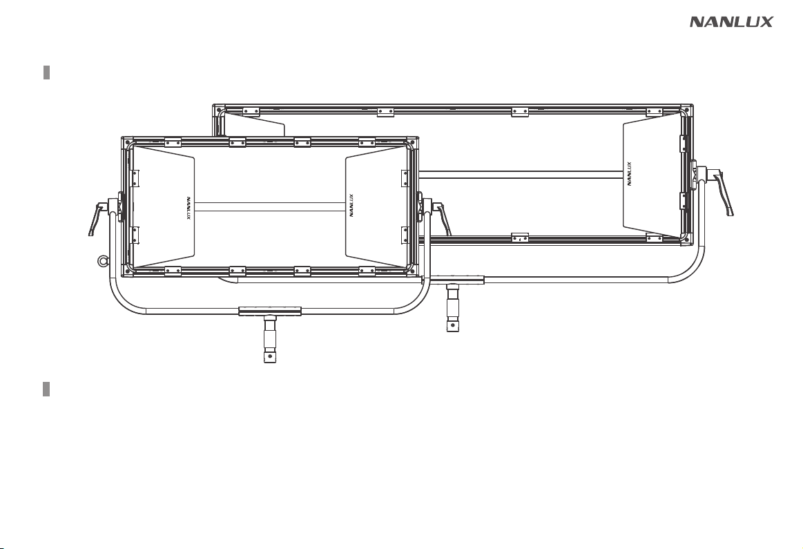
Product Diagram
Technical Data
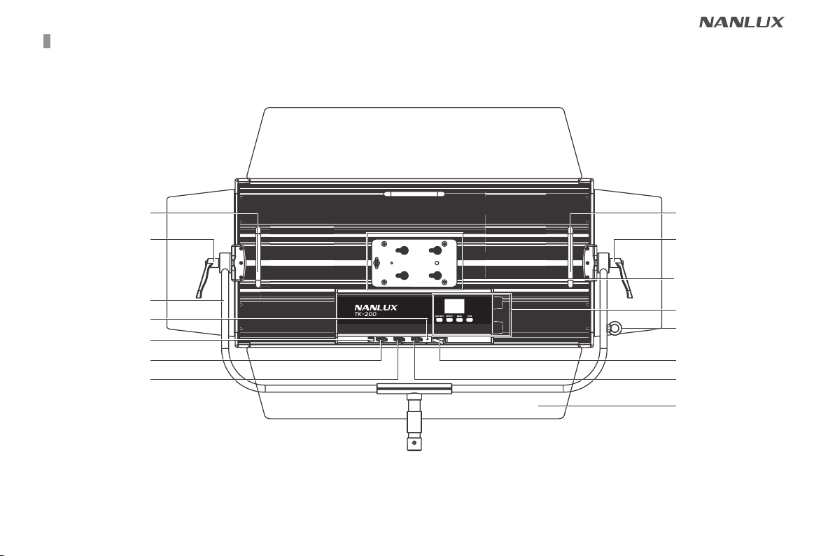
Product Details
Detailed Description
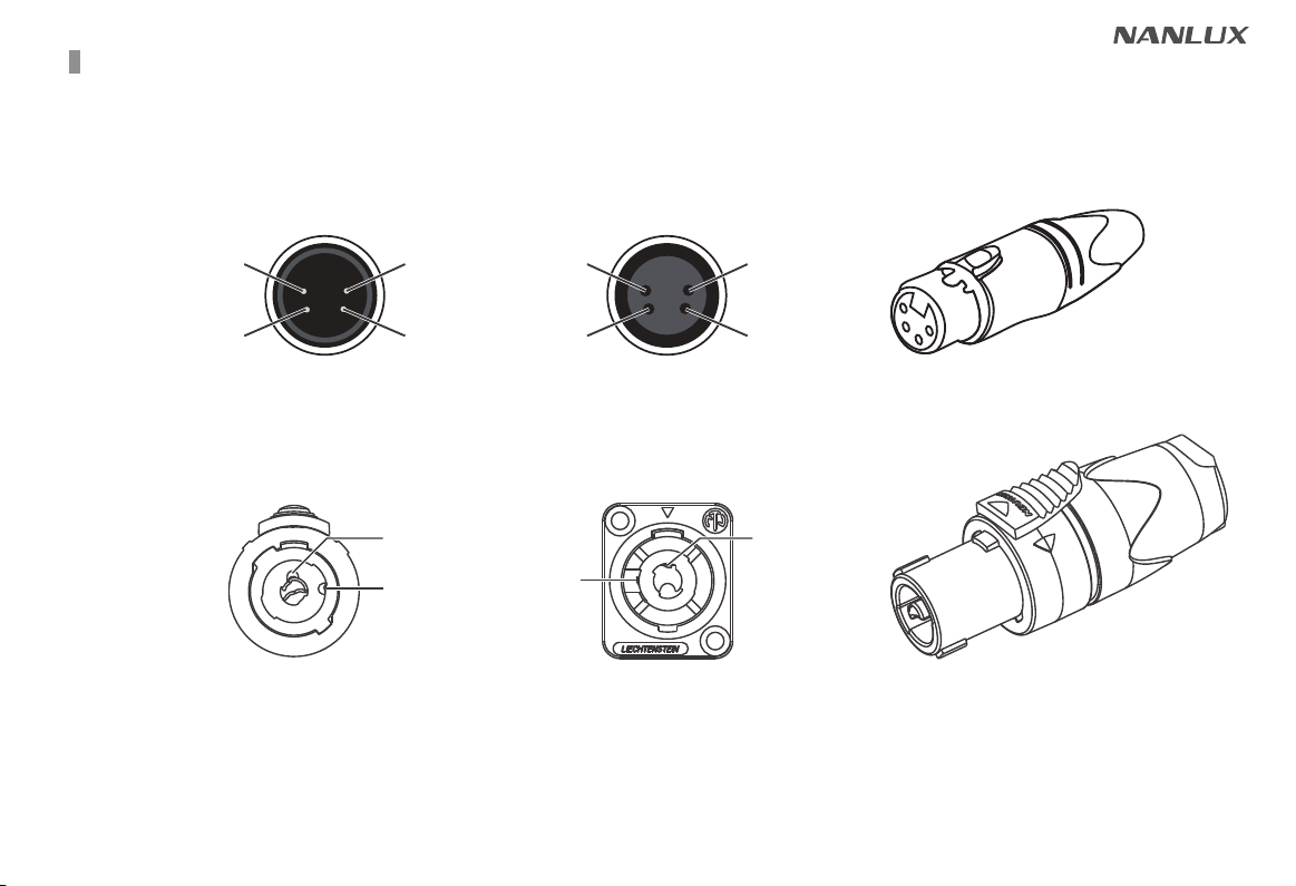
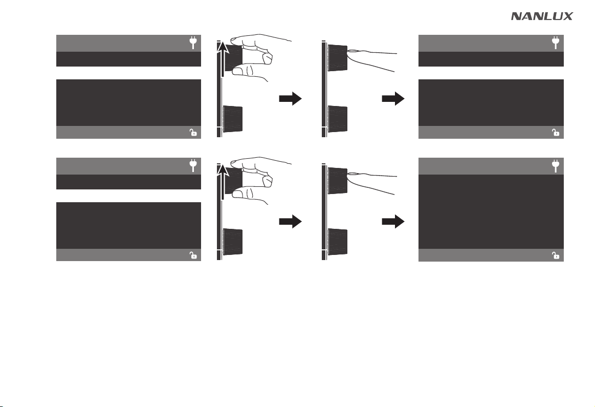
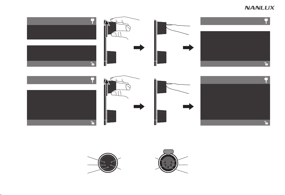
Power Connection
Remote Control
Operating Instructions
1. Screen Interface Display Instructions
2. DAYLIGHT Key
3. EFFECT Key
14
14
15
4. MENU Key
①
ADDRESS/DMX
②
WIRELESS PROTOCOL
③
LUMENRADIO SETTINGS
④
ROTATE SCREEN
⑤
SCREEN BRIGHTNESS
⑥
BUTTON BACKLIGHT
⑦
LANGUAGE
⑧
VERSION
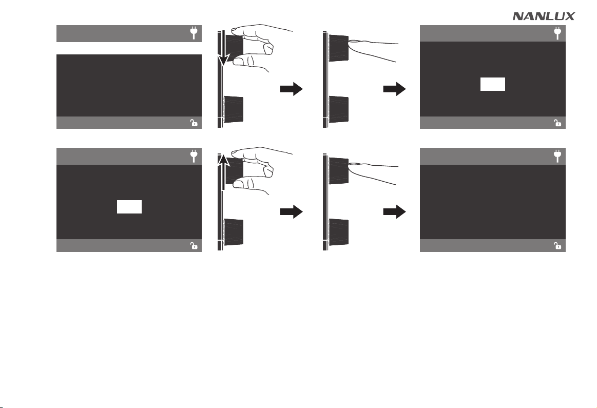
5. LOCK Key
Safety Precautions
Notice
Product Includes
05
08
10
11
12
............................................
..............................................................
.............................................................
..........................................................
.............................................
...........................................
...................................................
.........................................
............................................
.....................................................
.............................................................
....................................................................
................................................
General Fault Detection and Diagnosis ....... 35