manuals.online logo
Brands
  1. Home
  2. •
  3. Brands
  4. •
  5. NANLUX
  6. •
  7. Lighting Equipment
  8. •
  9. NANLUX Evoke 2400B User manual

NANLUX Evoke 2400B User manual

USER MANUAL
Guangdong NanGuang Photo&Video Systems Co., Ltd.
Evoke 2400B
LED Bi-color Spot Light
WWW.NANLUX.COM 01
Thank you for purchasing Nanlux product -- Eovke 2400B!
Evoke 2400B is a LED bi-color spotlight specifically designed for film and TV projects. It is equipped with rated power of 2400W, adjustable CCT of 2700K-6500K,
precise dimming in 0.1% increment, 12 effects, 4 fan CCTs, and 2 output CCTs. The multiple control methods include on-board, remote control, Nanlink App, DMX/RDM,
LumenRadio CRMX and Ethernet (Art Net, sACN). Both the fixture and power supply are built with metal structure and quick release mechanism, and IP55 rating, providing
precise, convenient and reliable lighting solutions for production. It's worth mentioning that Evoke 2400B also has modifier recognition function, for automatically recognizing
modifiers that with electronic contacts and limiting the power, ensuring safety while making it a more intelligent lighting equipment.
1. Please do not look directly at the emitter when the light is on, to avoid eyes discomfort caused by high luminance.
2. Please do not place the fixture near any flammables and explosives, to avoid fire hazard caused by high luminance.
3. Please do not immerse the fixture in water. While with IP55 rating, the light fixture can be used in the rainy situations.
4. Please ensure the fixture is dry before packing after using in the rain.
5. Please place the power cable and DC cable properly to avoid stumbled caused by long cables.
6. Please exchange the power cable if any damage is found, to avoid electric shock.
7. Please use the power cable and DC cable provided by the manufacturer as the power is high. Dangers like melting cable, electric shock or fire may happen if cables
of other brands are used.
8. Please do not block the vents when the fixture is on. The fixture is built with active cooling system, so ensure unimpeded vents to prevent the fixture from protection
state due to overheating.
9. Please do not disassemble the fixture to repair at will, to avoid damage to the fixture that contains precision electronic components. If repair is required, please return
to the distributor or have it repaired by any qualified technician.
10. Please switch the fixture off and unplug the cables before cleaning, to avoid electric shock.
11. Please do not use strong detergent for cleaning. Please wipe off the dirt by using a cloth with neutral cleanser when cleaning the fixture.
12. Please hold the handle securely when detaching the accessories or adjusting the beam directions, since the accessories such as Fresnel lens and softbox are heavy.
13. Please ensure that the power cable and DC cable are properly connected before powering the fixture, to avoid sparking and heating of the plug.
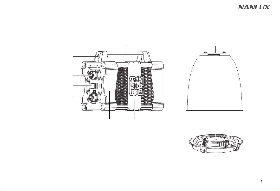
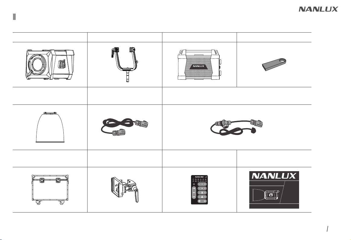
Introduction
Notice
WWW.NANLUX.COM 02
Product Diagram
Evoke 2400B
LED Bi-color Spot Light
Rated Power: 2400W
Input: DC48V/26A×2
AC100V-240V 50/60Hz 26A Max
Color Temperature: 2700K - 6500K (GM±80)
CRI: Average 96
TLCI: Average 97
Technical Data
WWW.NANLUX.COM 03
Product Details
3. NL Mount
4. Lock Catch
5. Eye Bolt
6. Yoke
1. Quick Release Device
2. Adjustable Handle
WWW.NANLUX.COM 04
15. Right Knob
16. Wire Control Socket
17.DMX IN
19.DC IN
18.DMX OUT
8. Display Screen
9. Buttons
10. Left Knob
11. Middle Knob
12. USB Port
14. LAN2
13. LAN1
7. Handle
WWW.NANLUX.COM 05
21. Hanging Hole
22. AC Power Input Socket
23. Power Switch
25. LED Indicator
24. DC Power Output Socket
27. Reflector20. Power Supply Handle
26. Quick Release Plate 28. COB Protective Cap
WWW.NANLUX.COM 06
1. Quick release device: For quick installation and detachment of yoke.
2. Adjustable handle: Tighten or release the tilt movement of the fixture on the yoke.
3. NL mount: For installing the reflector or other NL mount accessories.
4. Lock catch: To lock or release the reflector or other accessories.
Note: Please pull in the direction indicated on it.
5. Eye bolt: For hanging safety wire.
6. Yoke: Mount the fixture on a stand, also for pan and tilt.
7. Fixture body handle: Offer convenient grip for adjusting direction of illumination.
8. Display: To display data.
9. Buttons: Including CCT, EFFECT, MENU and LOCK.
10. Left knob: For adjusting brightness.
11. Middle Knob: For adjusting parameters for each option.
12. USB port: For updating firmwares or providing current with maximum 5V/1A to external devices via connecting the USB cable.
13. LAN 1: Network connecting port.
14. LAN 2: Network connecting port.
15. Right knob: For selecting options.
16. Wire control socket: Wire control interface.
17. DMX IN: DMX signal input interface.
18. DMX OUT: DMX signal output interface.
19. DC IN: DC power input interface.
20. Power supply handle: For lifting the power supply.
21. Hanging hole: For hanging the power supply.
22. DC power output socket: For connecting the fixture to the power supply with DC cable.
23. Power switch: To turn on/off the fixture.
24. AC power input socket: For connecting AC cable and supplying power to power supply.
25. LED indicator: For judging the power input state. Being on, means power supply normal; Flashing or being off, mean power supply abnormal or no power input.
26. Quick release plate: For mounting the quick release clamp.
27. Reflector: For concentrating light to improve the central illumination.
28. COB protective cap: For protecting the COB when the fixture is not in use.
(Note: Take off the cap before using.)
Detailed Description
WWW.NANLUX.COM 07
Includes (for CN, UK, AU, EU, KR)
Evoke 2400B×1
Evoke 2400B KIT-FO Flight Case Standard Kit (fixture only) :
Power Supply×1 USB Flash Drive×1
User Manual×1
AS-CP-QR-EV
Quick Release Clamp×1
CC-EV2400-FT-FO
Flight Case×1
WS-RC-C2
Remote Controller×1
Yoke×1
DC Connection Cable×1
Reflector×1
(packed separately) AC Power Cable×1
Evoke 2400B
USER MANUAL
Evoke 2400B
LED Bi-color Spot Light
Guangdong NanGuang Photo&Video Systems Co., Ltd.
WWW.NANLUX.COM 08
Includes (for US, JP)
Evoke 2400B×1
Evoke 2400B KIT-FO Flight Case Standard Kit (fixture only) :
Power Supply×1 USB Flash Drive×1
User Manual×1
AS-CP-QR-EV
Quick Release Clamp×1
CC-EV2400-FT-FO
Flight Case×1
WS-RC-C2
Remote Controller×1
Yoke×1
DC Connection Cable×1
Reflector×1
(packed separately)
AC Cable
with Edison Connector×1
Evoke 2400B
USER MANUAL
Evoke 2400B
LED Bi-color Spot Light
Guangdong NanGuang Photo&Video Systems Co., Ltd.
AC Cable
(with bare ends)×1
AC/L (brown)
AC/N (blue)
PE (yellow & green)
WWW.NANLUX.COM 09
1. Connection Between Light Fixture and Power Supply
Usage
WWW.NANLUX.COM 10
2. Installation and Detachment of Yoke
Lay down the light fixture on flat ground, with its
bottom up.
Press the quick release lever lock catch to release
the lever, and push the lever aside.
Firmly hold the yoke in place with one hand, and pull
the quick release lever with the other hand to lock the
plate.
Align and insert the quick release plates to the mounts
on both sides of the fixture.
Note: Please adjust the plate to right directions when
installing the quick release plate, then insert
them into the mount.
按扳手锁扣,扳手解锁,将扳手拨开。
WWW.NANLUX.COM 11
Mount the fixture on heavy-duty light stand and lock
the fastening screws on the light stand.
When disassembling the yoke, remove the fixture
from the heavy-duty light stand first and lay it down
on flat ground.
Press the quick release lever lock catch of the fixture
on both sides, then release the quick release lever to
remove the fixture.
WWW.NANLUX.COM 12
Installation of Yoke (Method Two)
Press the quick release lever lock catch and push
the lever aside, align and insert the quick-release
plate mounts to the plates of the yoke.
(Note: Please adjust the plate to right directions
when installing the quick release plate,
then insert them into the mount.)
Mount the yoke on heavy-duty light stand and lock
the fastening screws on the light stand.
Pull the levers on both sides of the fixture to lock the
quick release plate in place. The installation of the
yoke is completed.
WWW.NANLUX.COM 13
3. Installation and Detachment of Reflector
When installing the reflector, align the reflector to the NL mount on the fixture, rotate clockwise the reflector to fasten it on the fixture.
Note: 1. If the rotation is not smooth, pull the lock catch of the mount and rotate the reflector at the same time.
2. The electronic contacts on the accessories should be aligned with those on the fixture.
When removing the reflector, pull the lock catch of the mount, rotate anticlockwise the reflector and remove it.
WWW.NANLUX.COM 14
4. AS-CP-QR-EV Evoke Quick Release Clamp Installation
Rotate the adjustable handle to release the clamp.
Align the quick release plate on the power supply with the quick release mount
on the clamp, a click sound will be heard when the power supply is fastened in
place.
Mount the quick release clamp on the light stand, then rotate the adjustable handle
to tighten the clamp.
Press the lock catch on the clamp to remove the power supply from the light stand.
WWW.NANLUX.COM 15
MENU
CH: 512
SMART
ADDRESS
DMX MODE
DMX REDUCED CHANNELS
DMX DIMMING CURVE
DMX SMOOTHING
PRESS “MENU” TO RETURN
MENU
CH: 512
SMART
OUTPYT MDER
MODIFIER RECOGNITION
ADDRESS/DMX
WIRELESS CONTROL
NETWORK SETTINGS
Art-Net & sACN SETTINGS
MENU
CH: 512
SMART
OUTPYT MDER
MODIFIER RECOGNITION
ADDRESS/DMX
WIRELESS CONTROL
NETWORK SETTINGS
Art-Net & sACN SETTINGS
Rotate the right knob to ADDRESS/DMX, and press the right knob to enter the secondary menu.
Remote Control
·Evoke 2400B supports remote control via DMX/RDM, 2.4G, LumenRadio, Art-Net & sACN, and has built-in Bluetooth module as well.
▲The ADDRESS needs to be set before operating the remote control via DMX/RDM, 2.4G, LumenRadio, Art-Net & sACN.
1.1 ADDRESS
Press the MENU button to enter the interface.
1. ADDRESS/DMX, including ADDRESS, DMX CCT, DMX REDUCED CHANNELS, DMX DIMMING CURVE and DMX SMOOTHING settings.
CCT EFFECT MENU LOCK
middle knob right knobleft knob
WWW.NANLUX.COM 16
MENU
CH: 512
SMART
CCT 8bit
CCT 16bit
ULTIMATE DMX 8bit
PRESS “MENU” TO RETURN
MENU
CH: 512
SMART
ADDRESS
DMX MODE
DMX REDUCED CHANNELS
DMX DIMMING CURVE
DMX SMOOTHING
PRESS “MENU” TO RETURN
ADDRESS
512
MENU
CH: 512
SMART
PRESS “MENU” TO RETURN
ADDRESS
512
MENU
CH: 512
SMART
PRESS “MENU” TO RETURN
MENU
CH: 512
SMART
ADDRESS
DMX MODE
DMX REDUCED CHANNELS
DMX DIMMING CURVE
DMX SMOOTHING
PRESS “MENU” TO RETURN
1.2 DMX MODE
Rotate the right knob to ADDRESS, and press the right knob to enter the tertiary menu.
Rotate the right knob to select address number and press the right knob to set.
Rotate the right knob to DMX MODE and press the right knob to enter the tertiary menu.
SET
MENU
CH: 512
SMART
PRESS “MENU” TO RETURN
WWW.NANLUX.COM 17
SET
MENU
CH: 512
SMART
PRESS “MENU” TO RETURN
MENU
CH: 512
SMART
OFF
ON
PRESS “MENU” TO RETURN
MENU
CH: 512
SMART
OFF
ON
PRESS “MENU” TO RETURN
MENU
CH: 512
SMART
ADDRESS
DMX MODE
DMX REDUCED CHANNELS
DMX DIMMING CURVE
DMX SMOOTHING
PRESS “MENU” TO RETURN
SET
MENU
CH: 512
SMART
PRESS “MENU” TO RETURN
MENU
CH: 512
SMART
CCT 8bit
CCT 16bit
ULTIMATE DMX 8bit
PRESS “MENU” TO RETURN
Rotate the right knob to select CCT 8bit, CCT 16bit or ULTIMATE DMX 8bit, and press the right knob to set.
1.3 DMX REDUCED CHANNELS
Rotate the right knob to select ON or OFF and press the right knob to set.
Rotate the right knob to DMX REDUCED CHANNELS, and press the right knob to enter the tertiary menu.
WWW.NANLUX.COM 18
MENU
CH: 512
SMART
OFF
ON
PRESS “MENU” TO RETURN
MENU
CH: 512
SMART
LINEAR
EXPONENT
LOGARITHM
S CURVE
GAMMA 2.2
PRESS “MENU” TO RETURN
MENU
CH: 512
SMART
LINEAR
EXPONENT
LOGARITHM
S CURVE
GAMMA 2.2
PRESS “MENU” TO RETURN
MENU
CH: 512
SMART
ADDRESS
DMX MODE
DMX REDUCED CHANNELS
DMX DIMMING CURVE
DMX SMOOTHING
PRESS “MENU” TO RETURN
SET
MENU
CH: 512
SMART
PRESS “MENU” TO RETURN
1.5 DMX SMOOTHING
Rotate the right knob to DMX SMOOTHING and press the right knob to enter the tertiary menu.
1.4 DMX DIMMING CURVE
Rotate the right knob to select LINEAR, EXPONENT, LOGARITHM, S CURVE or GAMMA 2.2, and press the right knob to set.
Rotate the right knob to DMX DIMMING CURVE, and press the right knob to enter the tertiary menu.
MENU
CH: 512
SMART
ADDRESS
DMX MODE
DMX REDUCED CHANNELS
DMX DIMMING CURVE
DMX SMOOTHING
PRESS “MENU” TO RETURN
WWW.NANLUX.COM 19
MENU
CH: 512
SMART
OFF
ON
PRESS “MENU” TO RETURN
SET
MENU
CH: 512
SMART
PRESS “MENU” TO RETURN
Rotate the right knob to select ON or OFF and press the right knob to set.
2. DMX Control
2.1. Connect the light fixture and the DMX512 console using the connection cable, as below.
·5-pin shielded cable with a diameter not less than 0.3mm must be used for connection between light fixture and DMX/RDM console, or between light fixture and
light fixture. XLR plug/socket and the cable should be connected as picture above.
·Pin1, Pin2, Pin3 for connecting DMX signal. Pin4, Pin5 has no connection.
▲NOTE: When connecting DMX, make sure the internal pin is not in contact with the inner case. The fixture can match the DMX512 (1990) control signal.
·5-pin and 3-pin XLR plug/socket conversion
The fixture comes with 5-pin XLR plug/socket. lf a 3-pin XLR plug is used, please follow the instruction below.
DMX IN DMX OUT
1 GND
2 DATA-
3 DATA+
NC
NC
NC
NC
GND 1
DATA- 2
DATA+ 3
Three Pin
Pin 1:GND(SCREEN)
Pin 2:Signal(-)
Pin 3:Signal(+)
Five Pin
Pin 1:GND(SCREEN)
Pin 2:Signal(-)
Pin 3:Signal(+)
Pin 4:N/C
Pin 5:N/C

Other NANLUX Lighting Equipment manuals

NANLUX Evoke 1200 User manual

NANLUX

NANLUX Evoke 1200 User manual

NANLUX Evoke 1200B User manual

NANLUX

NANLUX Evoke 1200B User manual

NANLUX TK-200 User manual

NANLUX

NANLUX TK-200 User manual

NANLUX TK-140B User manual

NANLUX

NANLUX TK-140B User manual

NANLUX Dyno 650C User manual

NANLUX

NANLUX Dyno 650C User manual

Popular Lighting Equipment manuals by other brands

iGuzzini LASER BLADE 5 manual

iGuzzini

iGuzzini LASER BLADE 5 manual

MPK VisionVent S pro Installation and operating instructions

MPK

MPK VisionVent S pro Installation and operating instructions

Skytron STELLAR LFS Series owner's manual

Skytron

Skytron STELLAR LFS Series owner's manual

Robert Juliat 1015 B Technical file

Robert Juliat

Robert Juliat 1015 B Technical file

Osram Traxon e:cue Allegro Media Tube Lite installation guide

Osram

Osram Traxon e:cue Allegro Media Tube Lite installation guide

Knightsbridge SHE S Series Installation & maintenance manual

Knightsbridge

Knightsbridge SHE S Series Installation & maintenance manual

WE-EF XRY300 LED Series Installation and maintenance instructions

WE-EF

WE-EF XRY300 LED Series Installation and maintenance instructions

Larson Electronics HID-35-RC-W quick start guide

Larson Electronics

Larson Electronics HID-35-RC-W quick start guide

OSF POOLcontrol-40.net Installation and operating instructions

OSF

OSF POOLcontrol-40.net Installation and operating instructions

Excelitas Technologies XLED1 quick start guide

Excelitas Technologies

Excelitas Technologies XLED1 quick start guide

iSolution iMove 350SR user manual

iSolution

iSolution iMove 350SR user manual

ARRI EB 575/800 operating instructions

ARRI

ARRI EB 575/800 operating instructions

Argos FL-00240 instructions

Argos

Argos FL-00240 instructions

RAB STEALTH 360 installation manual

RAB

RAB STEALTH 360 installation manual

Clas Ohlson OCL-683 pimple-UK instruction manual

Clas Ohlson

Clas Ohlson OCL-683 pimple-UK instruction manual

Clas Ohlson 36-5862 quick start guide

Clas Ohlson

Clas Ohlson 36-5862 quick start guide

Hella 2SE 357 032-021 Installation instruction

Hella

Hella 2SE 357 032-021 Installation instruction

Viabizzuno F7.156.61 installation instructions

Viabizzuno

Viabizzuno F7.156.61 installation instructions

manuals.online logo
manuals.online logoBrands
  • About & Mission
  • Contact us
  • Privacy Policy
  • Terms and Conditions

Copyright 2025 Manuals.Online. All Rights Reserved.