USER MANUAL
1. ADDRESS/DMX
2. DMX Remote Control
3. 2.4G Remote Control
4. RDM Remote Control
5. LUMENRADIO Remote Control
01
............................................................
01
.................................................................
02
...............................................................
..................................................... 03
..................................................................
.........................................................
.........................................................
.........................................................
..........................................
................................
Contents
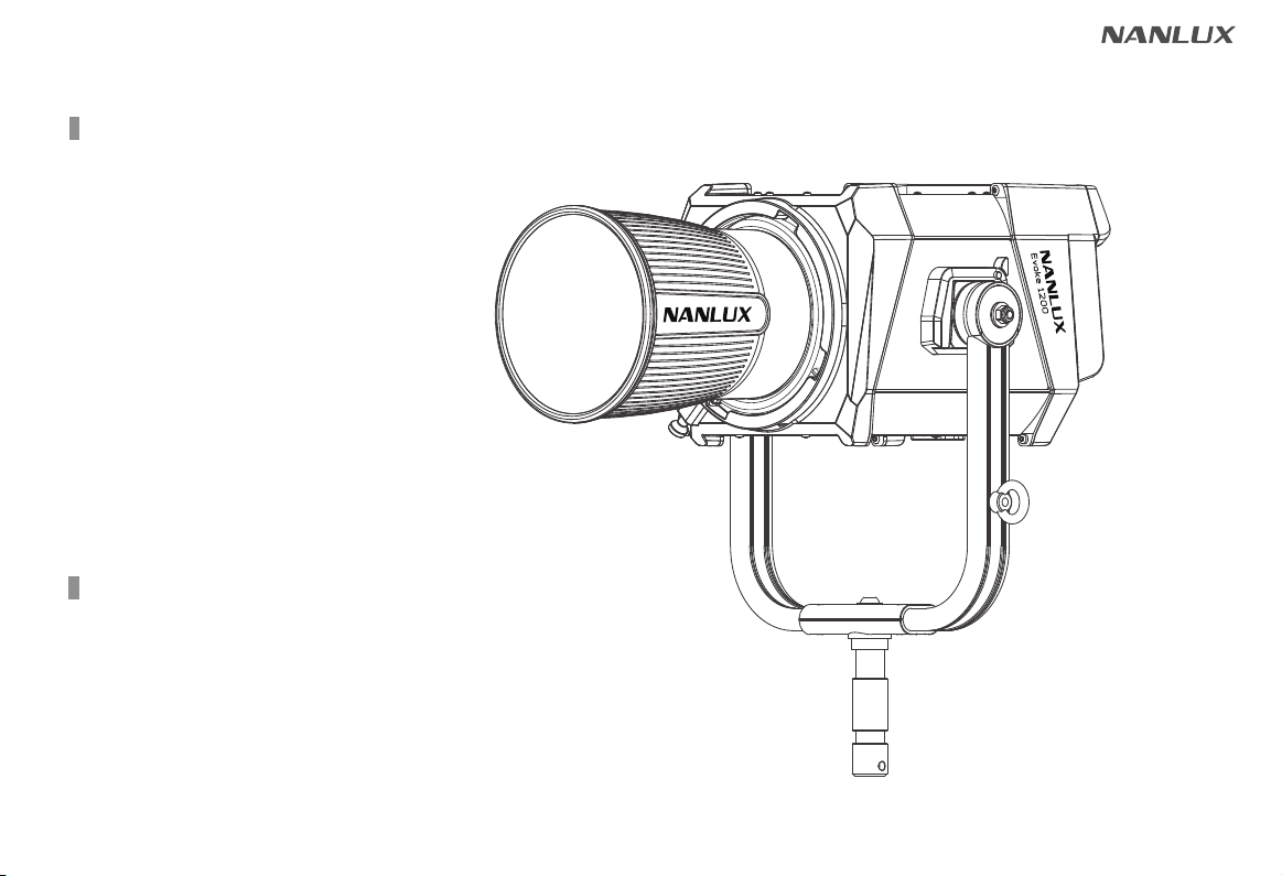
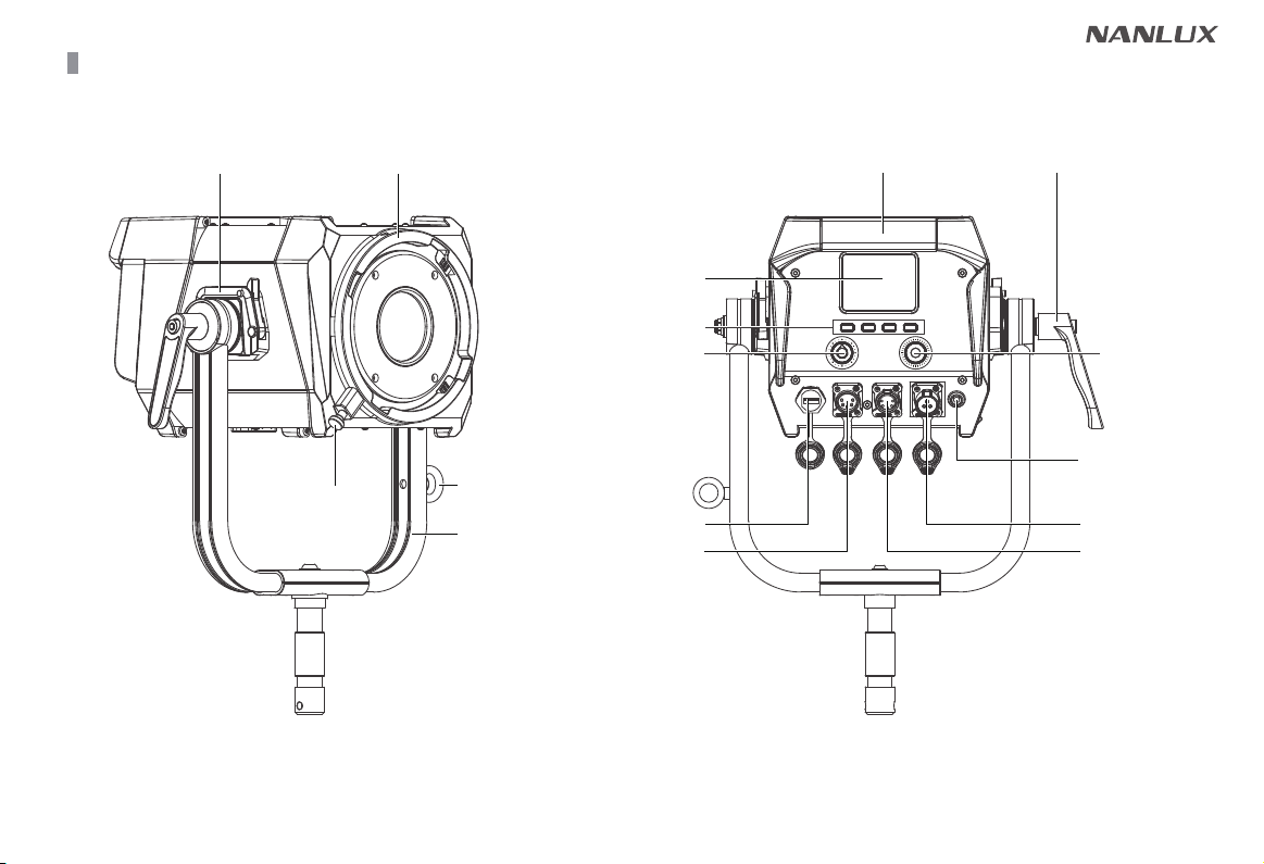
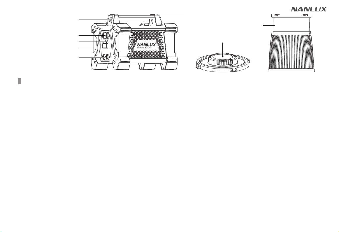
Product Diagram
Technical Data
Product Details
Detailed Description
Usage
Remote Control
Operating Instructions
1. Screen Interface Display Instructions 27
...........................................................
.................................................................
①
DAYLIGHT Key
2. EFFECT Key
27
28
....
..................................
...........................
.........
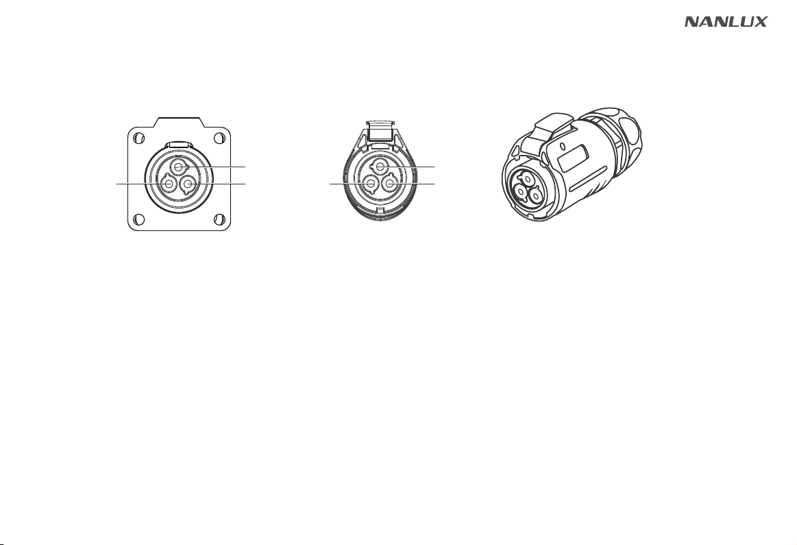
1. Connection between the Light Fixture and Power Supply
2. Installation and Detachment of Yoke
3. Installation and Detachment of Reflector
4. Installation of FL-35 Fresnel Lens and the Barndoor
04
06
10
11
3. MENU Key
①
ADDRESS/DMX
②
WIRELESS PROTOCOL
③
LUMENRADIO SETTINGS
④
FAN CONTROL
⑤
ROTATE SCREEN
⑥
SCREEN BRIGHTNESS
⑦
BUTTON BACKLIGHT
⑧
LANGUAGE
⑨
VERSION
42
42
42
43
44
45
46
47
48
42
48
4. LOCK Key
Safety Precautions
Notice
Product Includes
14
17
19
20
21
49
..................................................
.....................................................................
...................................................................
................................................................
..................................................
...............................................
.......................................................
...........................................................
............................................
................................................
..........................................................
....................................................................
49
.............................................................................
50
......................................................
General Fault Detection and Diagnosis ......... 49