Nanosonics trophon 2 User manual

L03030 1.0


L03030 1.0 03/2018 1
ENGLISH

L03030 1.0 03/2018 2
Read this manual before operating the trophon®2 to determine the correct procedures.
For further information, contact your customer service representative or visit the Nanosonics website.
All technical specifications and system approvals are listed in Appendix 1.
©2018 Nanosonics Limited. All rights reserved.
The content of this manual is correct at the time of product purchase.
trophon®2, NanoNebulant®and Sonex-HL®are registered trademarks of Nanosonics Limited.
AcuTraceTM is a registered trademark of Nanosonics Limited in Australia and other countries.
NanoNebulant is the product name of the trophon2 disinfectant used in all regions where trophon2 is
available for sale, with the exception of US and Canada.
Sonex-HL is the product name of the trophon2 disinfectant in the US and Canada.
Nanosonics’ technologies are protected by a combination of patents, trademarks, and exclusive
proprietary rights: http://www.nanosonics.com.au/nanosonics-patent
Your trophon2 representative is:
Attach Business Card or information sticker/stamp here.

L03030 1.0 03/2018 3
FCC Compliance Statement
This equipment has been tested and found to comply with the limits for a Class A digital device, pursuant
to part 15 of the FCC Rules. These limits are designed to provide reasonable protection against harmful
interference when the equipment is operated in a commercial environment. This equipment generates,
uses and can radiate radio frequency energy and, if not installed and used in accordance with the
instruction manual, may cause harmful interference to radio communications. Operation of this
equipment in a residential area is likely to cause harmful interference in which case the user will be
required to correct the interference at his own expense.
Warning: Any changes or modifications not expressively approved by Nanosonics could void the user's
authority to operate this equipment.
This device complies with Part 15 of the FCC Rules and Innovation, Science and Economic
Development (ISED) Canada’s license-exempt RSS standards. Operation is subject to the following
two conditions:
(1) This device may not cause interference; and
(2) This device must accept any interference, including interference that may cause undesired
operation of the device.
www.nanosonics.us ●www.nanosonics.com.au

L03030 1.0 03/2018 4
Table of Contents
Part A –WARNINGS, INTRODUCTION AND INSTRUCTIONS............6
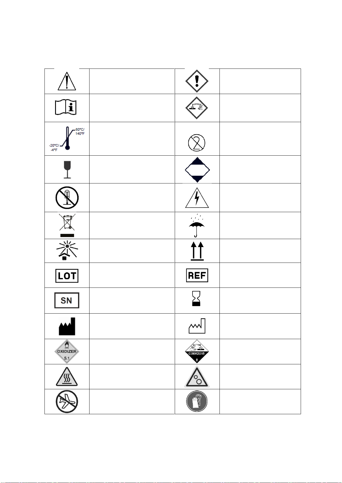
SECTION A1: Important Labels, Symbols and Warnings .........................................................6
A1.1 Labels and Symbols.............................................................................................................6
A1.2: Warnings................................................................................................................................7
SECTION A2: Introduction to the trophon2................................................................................8
A2.1 Indications for Use..................................................................................................................8
A2.2 Disinfection Process...............................................................................................................8
A2.3 Validated Probes, Disinfectants and Chemical Indicators......................................................8
A2.4 Training...................................................................................................................................8
A2.5 Environment and User Profile.................................................................................................9
SECTION A3: Instructions............................................................................................................9
Part B –SET UP..................................................................................10
SECTION B1: trophon2 Overview..............................................................................................10
B1.1 trophon2 Features ................................................................................................................10
B1.2 Cable Tray............................................................................................................................11
SECTION B2: Installation Guide................................................................................................12
B2.1 Positioning your trophon2.....................................................................................................12
B2.2 Powering On.........................................................................................................................13
B2.3 Initial Setup...........................................................................................................................13
B2.4 Warm up Cycle.....................................................................................................................13
B2.5 trophon2 Touch Screen........................................................................................................13
B2.6 Basic Settings.......................................................................................................................13
B2.7 AcuTraceTM ...........................................................................................................................13
B2.8 AcuTraceTM Settings.............................................................................................................14
SECTION B3: trophon AcuTrace PLUS.....................................................................................15
B3.1 Activation ..............................................................................................................................15
B3.2 Network Parameters Setup ..................................................................................................15
PART C –OPERATION.......................................................................15
SECTION C1: Loading the Disinfectant Cartridge...................................................................15
SECTION C2: Logging the trophon Chemical Indicators........................................................15
SECTION C3: Routine High Level Disinfection Cycle .............................................................15
C3.1 Preparing the Probe .............................................................................................................15
C3.2 Inserting the Chemical Indicator...........................................................................................16
C3.3 Positioning the Probe ...........................................................................................................16
C3.4 Closing the Chamber Door...................................................................................................18
C3.5 Disinfecting the Probe ..........................................................................................................18
C3.6 Removing the Probe.............................................................................................................19
C3.7 Sleep Mode ..........................................................................................................................19
PART D –RECORDS...........................................................................19
SECTION D1: Record Options ...................................................................................................19
PART E –MAINTENANCE AND ROUTINE CARE...............................20
SECTION E1: Preventative Maintenance Service ....................................................................20
SECTION E2: Purge Cycle..........................................................................................................20
E2.1 When to Run a Purge Cycle.................................................................................................20
E2.2 How to Initiate a Purge Cycle ...............................................................................................20
SECTION E3: Regular Cleaning.................................................................................................21
SECTION E4: Transporting the trophon2 .................................................................................21
SECTION E5: Disposal of trophon2 ..........................................................................................21
PART F –TROUBLESHOOTING..........................................................21
SECTION F1: Incomplete or Failed Cycles...............................................................................21

L03030 1.0 03/2018 5
F1.1 Mains Power Failure.............................................................................................................21
F1.2 Cycle Fault............................................................................................................................21
SECTION F2: Manual Door Lock Override................................................................................22
SECTION F3: Diagnostics ..........................................................................................................23
PART G –SERVICE REQUIREMENT AND WARRANTY PROVISION
.............................................................................................................25
APPENDIX 1: TROPHON2 TECHNICAL SPECIFICATIONS N05000-1
.............................................................................................................25
APPENDIX 2: PRODUCT WARRANTY TERMS AND CONDITIONS..26
APPENDIX 3: MicroDoc LICENCE AGREEMENT..............................27
APPENDIX 4: TROPHON2 ACCESSORIES* ......................................28
GLOSSARY .........................................................................................29

L03030 1.0 03/2018 6
Part A –WARNINGS, INTRODUCTION AND INSTRUCTIONS
SECTION A1: Important Labels, Symbols and Warnings
A1.1 Labels and Symbols
Caution
Warning
Consult instructions for use
Corrosive
Environmental Conditions:
trophon2 Storage and
Transport Conditions:
Temperature range: -20oC to
+60oC / -4oF to +140oF
Single Use Only
Fragile / Handle With Care
UN 2014 –Hydrogen
Peroxide
Do not disassemble
Dangerous Voltage
Separate collection for
electrical and electronic
equipment
Keep Dry
Keep Out of Direct Sunlight
This Way Up
Batch Number
Product Number
Serial Number
Expires
(year and month)
Legal Manufacturer
Date of Manufacture
Oxidizer –5.1
Corrosive –8
Warning: Hot Surface
Warning: Moving parts, do
not touch mechanism
Cannot be transported by air
freight
Wear Gloves

L03030 1.0 03/2018 7
Environmental Conditions:
trophon2 Operating
temperature range: 17oC to
27oC / 62.6oF to 80.6oF
AcuTraceTM RFID Zone
Start Up from sleep
Cycle Start
Menu
Integrated Probe Positioning Guide
A1.2: Warnings
Hot Temperatures
Do NOT touch surfaces in the internal chamber. They can be hot and cause burns.
To avoid probe damage, ensure the probe is correctly positioned in the chamber. (See section
C3.3 for correct positioning of probe.)
Malfunctions
Do NOT attempt to open the chamber door during a cycle, power failure or system malfunction.
All repairs must be carried out by trained personnel.
Transporting the trophon2
Follow your facilities manual handling procedures for guidance on lifting heavy
objects.
The trophon2 weighs approximately:
Unpackaged 22kg (48.5lb).
Packaged 25kg (55lb).
If your trophon2 has been used, purge the trophon2 before transportation to remove the
disinfectant. (See section E2).
Electrical Device
Use the power cable supplied with the trophon2, connect to an earthed power outlet with the
correct voltage and frequency as specified on the product and in Appendix 1. Incorrect voltage
can damage the product.
The trophon2 must not be connected to the same circuit as a critical patient or life support device.
Spilled fluid can result in electrical shock. Avoid spilling fluids on or around the trophon2. Do not
immerse any parts of the trophon2 in liquid.
Do not attempt to access the internal mechanics. This may result in electric shock.

L03030 1.0 03/2018 8
Protective Wear and Spills
Wear clean disposable gloves throughout the complete High Level Disinfection (HLD) process
including but not limited to running the trophon2 and handling:
- Disinfectant cartridges. Temporarybleaching and/or irritation of the skin may occur if gloves
are not worn.
- Probes before and after a HLD cycle.
- Chemical Indicators before and after a HLD cycle.
- Waste drawer when emptying or obtaining the Manual Door Lock key.
Wear appropriate personal protective equipment (PPE) when managing spills.
Never return spills to original cartridges for re-use.
SECTION A2: Introduction to the trophon2
A2.1 Indications for Use
The trophon2 is designed to provide High-Level Disinfection (HLD) of validated ultrasound probes.
High-Level Disinfection is achieved by surface exposure to a controlled dose of hydrogen peroxide
mist delivered to a disinfection chamber containing the ultrasound probe.
The trophon2 system consists of a multiple use instrument combined with a single use disinfectant
“trophon Sonex-HL”, delivered from a multi-dose cartridge.
The trophon2 is suitable for use in general hospital and health care facilities by trained personnel.
The trophon Sonex-HL should be used with the following contact conditions:
Minimum Operational Cycle Time: 7 minutes
Minimum Concentration: 31.5%
Minimum Disinfectant Dose: 1.0 g
Minimum Chamber Temperature: 56°C
The trophon2 is NOT intended to reprocess single-use devices or pre-clean medical instruments.
Chemical indicator use is required with every HLD cycle. Only the trophon Chemical Indicator product
is the approved chemical indicator for use with trophon2.
A2.2 Disinfection Process
At the start of the HLD cycle, the trophon2 creates an aerosol of concentrated hydrogen peroxide. This
is distributed over the exposed surface of the probe providing thorough HLD of the probe’s shaft and
handle. Once used, the hydrogen peroxide is converted into its constituents; oxygen and water. During
a purge cycle, the converted oxygen is vented into the atmosphere and the water is collected inside the
waste drawer located at the side of the trophon2 for emptying.
The contact conditions are fixed cycle parameters that the end user cannot modify.
A2.3 Validated Probes, Disinfectants and Chemical Indicators.
For details of probes that can be used in the trophon2, refer to the Validated Probe List on the
Nanosonics website.
Use only trophon Sonex-HL disinfectant cartridges and trophon Chemical Indicators when high level
disinfecting with the trophon2. No other disinfectant or chemical indicator has been approved for use
with the trophon2.
A2.4 Training
Before setting up or using your trophon2, ensure that all users are trained in safety procedures and
potential hazards, as outlined in this manual.
Visit www.nanosonicsacademy.com to complete the online training module.

L03030 1.0 03/2018 9
A2.5 Environment and User Profile
The trophon2 is designed for use in healthcare facilities to high level disinfect ultrasound probes under
the control of trained healthcare professionals.
The disinfection cartridge, Chemical Indicator, and trophon2 system are designed to be used with
minimal personal protective equipment (gloves only) and in a standard workplace or clinical setting,
including at the patient point-of-care. Special ventilation and other safety precautions are not required
when used as per these instructions.
SECTION A3: Instructions
Read these instructions before using the trophon2:
Safety Data Sheet (SDS) enclosed with the trophon2.
Occupational or Workplace Health and Safety Guidelines (OH&SG, OSHA, WHS) for your
institution for lifting, spills etc.
trophon Chemical Indicator Instructions for Use (IFU).
trophon disinfectant cartridge IFU.
trophon accessory IFUs for any additional accessories purchased with the trophon2 (see
Appendix 4).
Probe manufacturer’s instructions.
Failure to follow instructions may result in:
Burns, bleaching, electric shock or other injury.
High level disinfection not achieved.
Residual disinfectant remaining on the probe, which may cause injury when removing.
Equipment damage.

L03030 1.0 03/2018 10
Part B –SET UP
SECTION B1: trophon2 Overview
B1.1 trophon2 Features
Front
Back
Figure 1
Figure 2
Right Side
Left Side
Figure 3
Figure 4
8
10[
9
7
1
2
3
4
5
6

L03030 1.0 03/2018 11
Chamber
1. AcuTrace reader.
2. User Interface (UI).
3. Chamber door handle.
4. Manual door lock opening
mechanism cover.
5. Cartridge door. Warning: Do NOT
force open (cartridge door will
automatically open when required).
6. Waste drawer.
7. Power switch.
8. Power socket.
9. Ethernet port.
10. 3 x USB Ports.* **
11. Chamber door (opened).
12. Chemical Indicator holder.
13. Probe in correct position.
14. Door lock mechanism. Warning: Do
NOT put fingers into mechanism.
15. Cable clamp.
16. Cable seal.
17. Integrated Probe Positioner (IPP).
* trophon2 does not support Wi-Fi dongles or
3G/4G dongles.
** The 3 USB ports may be used in any order.
Figure 5
B1.2 Cable Tray
The cable tray holds the ultrasound cable away from the chamber door and stores the cable during
HLD. Remove the tray for cleaning (figure 6) and wipe with a cloth moistened with a soapy solution.
Figure 6
12
13
11
15
16
17
14
11

L03030 1.0 03/2018 12
SECTION B2: Installation Guide
B2.1 Positioning your trophon2
trophon2 weighs approximately 22kg (48.5 lbs). Follow your facilities manual handling
procedures for guidance on lifting heavy objects
1. Ensure the surface is level, can support the weight and allows adequate airflow (see Appendix
1).
2. There are no specific illumination requirements to use the trophon2. Follow your facilities
standard for work environment illumination guidance.
3. Ensure the area around your trophon2 is free from other equipment and clutter. Position as shown
in Figure 7 to ensure access to all features.
The trophon2 can also be mounted to the wall using the trophon Wall Mount 2 or for a mobile
solution, the trophon Cart. Please refer to the product IFUs for details.
The trophon2 should be placed at a height from the floor level to accommodate a range of
user heights. Refer to Figure 8 for a guide to an ergonomically safe work zone.
Figure 7
Distance on each side of
trophon2:
A = 250mm (10 in)
B = 250mm (10 in)
(not to scale)
Suggested Mounting Height
Figure 8

L03030 1.0 03/2018 13
B2.2 Powering On
The trophon2 must not be connected to the same circuit as a critical patient or life support
device.
1. Attach the power cable supplied to the trophon2 power socket.
2. Connect to mains power.
3. Turn on the power switch, located on the left side of the trophon2.
NOTE: To maximise the life of the disinfectant cartridge, keep your trophon2 switched on at all times,
except when moving the device.
B2.3 Initial Setup
The Initial Setup launches automatically, prompting you to configure the optional settings when
turning on the trophon2 for the first time. Follow the on screen instructions.
B2.4 Warm up Cycle
1. The warm up cycle prepares the trophon2 for operation and will begin automatically when the
machine is powered on.
2. The screen message will indicate when the warm up is complete and the trophon2 is ready for
use. Follow the on screen instructions.
B2.5 trophon2 Touch Screen
The trophon2 is operated using the touch screen User Interface (UI).
NOTE: The UI can be used with gloves.
Cleaning the trophon2 Touch Screen
The screen can be wiped clean using a soft, nonabrasive and lint-free cloth or wipe.
B2.6 Basic Settings
The available settings are:
Sleep Time: The default inactive period until the trophon2 enters sleep mode is two hours, which
can be adjusted in this setting.
Language
Date and Time
Printer
Daily Warm Up: A time can be set to begin the daily warm up of the trophon2.
Brightness and Alarms
Network
To access:
1. Select Menu
Settings
2. Select the required setting and follow the on screen prompts.
B2.7 AcuTraceTM
AcuTrace is an automated HLD traceability system that incorporates Radio Frequency Identification
(RFID). AcuTrace enabled accessories and consumables contain RFID chips that store digital
information and can be read by the in-built AcuTrace reader.

L03030 1.0 03/2018 14
The trophon2 AcuTrace Reader is located on the device as shown:
AcuTrace compatible products that are embedded with an RFID chip can be
identified by this symbol:
Scan the symbol on the AcuTrace reader when prompted.
Products that are AcuTrace compatible have this symbol on the outer packaging:
This symbol cannot be read by the AcuTrace reader.
The following products are compatible with AcuTrace:
trophon AcuTrace Operator Card
trophon AcuTrace Operator Card links the HLD cycle to the operator responsible for various aspects
of the workflow. The trophon2 screen will prompt the operator to scan their Operator Card against the
AcuTrace reader when preparing a probe for disinfection.
trophon AcuTrace Medical Instrument Tag
trophon AcuTrace Medical Instrument Tag stores probe identification information. Attach the trophon
AcuTrace Medical Instrument Tag at a distance from the probe that will not interfere with the patient
exam or closing of the trophon door. The tag is scanned on the AcuTrace reader when prompted by
an on screen message, prior to HLD, to link the HLD cycle to the disinfected probe.
trophon Chemical Indicator and Disinfectant
The AcuTrace compatible trophon Chemical Indicator box and disinfectant cartridges can be scanned
by the AcuTrace reader to track batch and expiry dates of these products.
Refer to the products’ Instruction for Use (IFU) for more information on their AcuTrace capabilities.
B2.8 AcuTraceTM Settings
AcuTrace features can be enabled or disabled via the trophon2 menu. Press:
1. Menu
AcuTrace.
2. Select the required setting for update and follow the on screen prompts.

L03030 1.0 03/2018 15
SECTION B3: trophon AcuTrace PLUS
trophon AcuTrace PLUS allows trophon2 to connect to Hospital Information Systems for automated
sharing and centralised storage and processing of disinfection data and enables Parametric Release.
B3.1 Activation
trophon AcuTrace PLUS will be prompted during the Initial Setup and can be activated through the
product trophon AcuTrace PLUS Activation Card. Follow the on screen instructions during the initial
setup.
To activate after initial setup, select:
Menu
AcuTrace
AcuTrace PLUS
Follow the on screen instructions.
B3.2 Network Parameters Setup
Consult your facilities IT administrator or network parameters expert to complete this setting.
The device supports the TCP/IP protocol. Set the IP address using the Dynamic Host Configuration
Protocol (DHCP) or a static configuration, select:
Menu
Settings
Network
When configured using DHCP, the device will be assigned a valid IP address from the router.
To set the IP address with the static configuration, please check prior with a network administrator to
ensure that the IP address is not in use and advise the appropriate values for the subnet mask and
the default gateway.
PART C –OPERATION
SECTION C1: Loading the Disinfectant Cartridge
The cartridge door opens automatically, DO NOT force open.
A trophon2 disinfectant cartridge needs to be inserted into the trophon2 before a HLD cycle can
commence.
Refer to the disinfectant IFU for detailed instructions on how to scan and log, insert, or remove
disinfectant cartridges.
Inserting a Disinfection Cartridge
The trophon2 screen will automatically prompt to scan (if AcuTrace is enabled) and insert a new
disinfectant cartridge, when required. Follow the on screen instructions and refer to the
disinfectant IFU.
SECTION C2: Logging the trophon Chemical Indicators
No other chemical indicators are approved for use in the trophon2.
If AcuTrace is enabled, log the new batch of Chemical Indicators by selecting:
1. Menu
AcuTrace
Log New Chemical Indicators.
2. Follow the on screen instructions.
SECTION C3: Routine High Level Disinfection Cycle
C3.1 Preparing the Probe
Wear gloves throughout the complete HLD process.
Clean and dry the probe and check clearly for probe defects BEFORE commencing the high level
disinfection process, as per the probe manufacturer’s instructions. Ensure that the probe has been
thoroughly dried after cleaning and no visible debris is present.

L03030 1.0 03/2018 16
C3.2 Inserting the Chemical Indicator
A whole trophon Chemical Indicator must be used for each disinfection cycle and may only be used
once. Refer to the Chemical Indicator IFU.
C3.3 Positioning the Probe
1. If AcuTrace is enabled, when prompted, scan the trophon AcuTrace Medical Instrument Tag and
Operator Card.
2. Open the chamber door and load probe and Chemical Indicator.
3. Two clamps (see Figure 9) hold the probe cable securely in the chamber.
4. Wear gloves and insert the probe into the trophon2 by gently pulling the probe cable against the
cable clamp (see Figure 9a). Then carefully pull the cable upwards until the probe is suspended
in the correct location and the probe cable is held by the cable seal (see Figure 9b). Refer to
figures 10-12 and note a correctly positioned probe in the trophon2.
Do not pull the probe down when loaded in the cable clamp.
Figure 9
a
b

L03030 1.0 03/2018 17
Figure 10
Figure 11
5. Ensure that the probe is correctly positioned in the chamber. The probe must not make contact
with the chamber wall and must be positioned at or above the embossed line at the bottom of the
chamber.
6. If the probe is disconnected from its connector end, the external portion of the cable and
connector can be secured by placing the connector carefully inside the cable tray.
NOTE: Incorrect positioning of the probe may result in:
Unsuccessful HLD cycles.
Residual disinfectant remaining on the probe’s surface. This may lead to temporary bleaching
and / or irritation of the skin if gloves are not worn.
Damage to the probe may occur if in contact with the chamber wall.
NOTE: Curved probes must be correctly inserted in the trophon2. See Figure 12.
Figure 12

L03030 1.0 03/2018 18
Curved Probes
The Integrated Probe Positioner (IPP) improves the positioning of approved curved probes in the
trophon2 chamber (refer to the Validated Probe List).
Position the probe curve towards the left of the trophon2 chamber. To engage the IPP, once the
probe is inserted into the probe clamp, push the left side of the IPP and slide to the right (see Figure
13a). This should displace the probe cable till the probe is no longer in contact with the chamber wall
(Figure 12).
To release the IPP, depress the trigger (see Figure 14a) and slide to the left.
Figure 13
Figure 14
C3.4 Closing the Chamber Door
The chamber door utilises a two stage closure mechanism. Carefully close the chamber door to
the first click and do NOT force shut. The door will automatically close further to seal and lock at
the start of the HLD cycle.
If the door is not properly closed, a screen message will prompt to close the chamber door.
DO NOT force or manually unlock the chamber door during a HLD cycle.
C3.5 Disinfecting the Probe
Once the door is closed, the trophon2 will request confirmation that the probe is clean and dry prior to
HLD. The door will lock upon confirmation.
1. Scan the trophon AcuTrace Operator Card when prompted (if AcuTrace enabled) and follow the
on screen instructions.
a
a
Other manuals for trophon 2
1
Table of contents
Languages:
Other Nanosonics Medical Equipment manuals
Popular Medical Equipment manuals by other brands

Akces-Med
Akces-Med DALMATIAN Use and Maintenance Instruction

B. Braun
B. Braun Aesculap AdTec mini Disassembly and Assembly Instructions

B. Braun
B. Braun Aesculap Surgical Instruments Instructions for use

I-Tech
I-Tech MIO-PERISTIM user manual

PRISM+
PRISM+ FSG200 quick start guide

C-me
C-me NIKI V4 Service manual

ARJO HUNTLEIGH
ARJO HUNTLEIGH enterprise 9000 Instructions for use

Cooper Surgical
Cooper Surgical Wallach WA1000B manual

Micro Direct
Micro Direct CO Check Pro operating manual

Smith & Nephew
Smith & Nephew RENASYS GO Series user manual

Morzine Medical
Morzine Medical Doak MK4 user guide

Tarta
Tarta Kid Pro user manual