NASAN ST WIN User manual

Rev 8, Dated 27-2-2018
1
ST WIN
Service Manual
Nasan Medical Electronics Pvt.Ltd
© All Rights Reserved

Rev 8, Dated 27-2-2018
2
TABLE OF CONTENTS
1. INDEX
2. PROCEDURES LIST
3. SYSTEM DIAGRAMS AND CONNECTIONS
4. SYSTEM CONFIGURATION
5. PROBLEMS,SOLUTIONS AND MATERIAL REQUIRED TO
SOLVE THE CALL
6. APPENDIX
A. TREADSTAR TABLE
B. USE OF CLAMP METER
C. 15 PIN SIGNAL DETAILS
D. TOOLKIT
E. BASIC PATIENT PREPARATION
F. IMPORTANT NOTE
G. EARTHING
H. STANDARD PROCEDURES
I. PRECAUTIONS
7. SERVICING OF TREADMILL CONTROLLER AND BODY LEVEL USED
WITH HIGH FREQUENCY DRIVE

Rev 8, Dated 27-2-2018
3
1. INDEX
Nature of Problem
Page No
Elevation Related 6 to 11.
Speed Related 11 to 17.
Software Related 18 to 20.
Miscellaneous 20 to 21.
Procedures List 27 to 38.
2. PROCEDURES LIST.
NO PROCEDURE LIST PAGE
NO.
1. Independent testing of the treadmill 27
2. Changing of 10 K10 turn pot. 27
3. Changing of AC motor. 29
4. Changing of Dc motor. 30
5. Changing of AC card+ DC drive Assembly to ACDC
drive combined.
30
6. Changing of actuator. 32
7. Changing of rollers. 33
8. Changing of Rack and pinion. 34
9. Changing of magnet. 34
10. Changing of limit switch 34
11. Changing of Conveyer belt. 34
12. Standard calibration procedure. 35

Rev 8, Dated 27-2-2018
4
3) SYSTEM DIAGRAMS:
Fig 1. BLOCK DIA OF ST-WIN SYSTEM
230V AC
MAINS
STWIN
AMPR
TREADMIL
L & COMPR
TREADMILL
PC
TO
PATIENT
FUSE 2A
POWER CORD
COMING FROM
AC MAINS
ON OFF
SWITCH
15 PIN
CONNECTOR
GOING TO
TREADMILL
(TPC cable)
LED INDICATION
FOR SPEED AND
ELEVATION
9-PIN
SERIALPORT
CONNECTOR
GOING TOWARDS
PC
Fig 2. AMPLIFIER CONNECTIONS

Rev 8, Dated 27-2-2018
5
4) MINIMUM SYSTEM CONFIGURATION
Minimum Requirement of PC for ST-Win system
1. Motherboard: Recommended
MAKE: D-Link/ASUS/INTEL/HIS
CHIPSET: Intel/VIA
SPEED: FSB, 400 MHz and onwards
2. CPU: Recommended
MAKE: Intel P-4, Speed 2.4 GHz, 400FSB
3. RAM: Recommended
Make: Symtronics/Hyundai/Transcend.
Size: 128 MB
Speed: 266 MHz
4. Serial Ports (RS-232): One working free serial port for ST-Win
amplifier.
5. VGA card: 64 bit, 2 MB memory PCI VGA card or onboard.
6. Monitor: 14” color monitor or onboard.
7. SMPS: Recommended
Make: Priya/Mercury/Intex.
Capacity: 300 Watt.
8. Hard disk: Recommended
Make: Seagate
Size: Barracuda 40 Gb 7200 RPM or onwards.
9. Display Settings: Resolution-1024*768
Font-Small font.
Color-16 bit hi color.
10. Key Board: PS/2 with 101 keys.
11. Mouse: PS/2.
12. Operating System: Windows 98/2000/XP/Win 7
13. Stabilizer: 3.5 KVA Servos (For treadmill only).
14. CD ROM: Recommended
Make: LG/Samsung/Sony/ASUS.
Type: Speed 52X
15. Printer: Recommended
Type: HP Laser Jet 1000/HP Laser Jet 1010 of USB port
HP Laser Jet 6L Gold/Pro.
16. Independent earthing connection.

Rev 8, Dated 27-2-2018
6
5) PROBLEMS, SOLUTIONS AND MATERIAL REQUIRED TO SOLVE THE CALL.
PROBLM
NO
PROBLEM PAGE
NO
1. Speed Related.
1. Speed reduction in second stage and onwards 6
2. No speed(conveyor belt is not moving at all) 8
3. Speed and elevation not as per protocol through software 9
4. Speed goes on increasing when we switch on the
TM(Uncontrolled speed)
9
5. Fuse blows as speed goes on increasing. 10
6. Jerk in speed/Speed reduces as patient walks on treadmill 10
7. Elevation is correct but speed incorrect in protocol 11
2. Elevation Related.
1. No elevation 11
2. Treadmill runs smoothly for 1
st
couple of stages, after that
it elevates randomly.
12
3. Treadmill stuck/elevates to its top position 12
4. On/Off switch(mcb) of treadmill trips down 13
5. Treadmill elevates properly up to 1
st
stage only and no
further elevation
14
6. Treadmill elevates/de-elevates slightly 14
7. No medians and no heart-rate. 16
8. While coming down treadmill not stopping. 17
9. Slow speed and slight elevation before 1
st
stage. 17
3. Software Related.
1. PC getting hanged while running software. 18
2. Communication error. 18
3. Noise in ECG when patient walks on treadmill or even if he
stands on treadmill.
19
4. Error of DAO setup or error as ‘STWIN 98 mdb’ file not
found.
19
5. Error as ‘STWIN 98-mdb’ file missing. When we install
DAO Setup for ST Win 3.74 from CD ROM, it works fine. But
when we remove the CD, then an error as ‘.mdb’ file missing
comes.
19
6. Lead 1 is coming inverted 19
7. Spikes during the test due to which HR is more than actual
value.
20
4. Miscellaneous.
1. Treadmill non-functional again and again. 20
2. 10K-10-turn pot getting burned. 21
3. ST-Win amplifier fuse blowing. 21
4. Base line wandering while test is going on. 21
5. Noise observed on lead V6 22
6. Spike in ECG 22

Rev 8, Dated 27-2-2018
7
1) SPEED RELATED.
NOTE: - Always connect Clamp meter before servicing the treadmill through live
wire of AC/DC card/High frequency drive and then check current is in range.
Problem
1.
Speed reduction in second stage and onwards
Background:
In calculating speed of treadmill, we are adhering to the following
principles:
1. We use a pmdc motor, which is required to drive the treadmill with
high speed. To drive the motor and subsequently the treadmill at
different appropriate speed we use dc drive (Refer fig 3 top view).
2. Any medical equipment must be precise, and it should have
continuous feedback. A closed feedback is maintained by following
method:
a. At the side of dc motor our treadmill has a heavy
wheel, which is called as flywheel. There is a
magnet embedded on this flywheel. At
approximately 5 mm from the flywheel, a sensor is
located (Refer fig 4).
b. Each time the flywheel rotates one cycle the sensor
detects it and the LED on AC/DC card flashes. If the
LED is not flashing on every rotation of flywheel
then correct speed will not be detected.
c. Even if the sensor is too near to the flywheel then it
will not detect the speed properly.
(Note: It is essential that the sensor should be between 5 mm
to 7 mm from flywheel and the (d41) LED should flash when treadmill
is running.)
Possible cause:
Generally this happens when the sensor whose function is to sense the
flywheel revolution, is very close to flywheel (Refer fig 3).The solution to
this is that the distance between the flywheel and the sensor should be
between 5mm and 7mm.
Check points/Solution:
1. Check weather sensor connection is loose
2. Interchange sensor connections wires from 2 pin relimate connector
3. If still problem persists, change ACDC drive
4. If still problem persists change ST Win amplifier.
Material
Req.
Sensor coil, silicon oil (200ml).

Rev 8, Dated 27-2-2018
8
Fig. 3 TOP VIEW
AC MOTOR
FRONT
ROLLER
CONDENSOR
GEAR BOX
AC/DC
COMBINE
D CARD
FLYWHE
EL
SPEED
SENSOR
DC MOTOR

Rev 8, Dated 27-2-2018
9
Fig 4. SPEED SENSOR
Problem
2.
No Speed (Conveyor belt is not moving at all)
Check Points/Solution
1. Run test treadmill program (Refer procedure 12) and click
appropriate buttons for speed increase and decrease.
2. Observe the speed increase/ decrease LEDs on back panel of the
STWIN amplifier (Refer fig 2).If LEDs are glowing, then the
problem lies in TPC cable or in treadmill.
3. But if the LEDs are not glowing then the problem lies with
STWIN amplifier or calibration factors are incorrect.
4. Check TPC cable continuity, if needed cut both ends and resolder
the cable (Refer fig 13 for Cable Details).
5. If belt is not moving while testing the treadmill independently
then the problem probably lies on the treadmill side. First check
whether the speed indication feedback LED (Fig 9) is glowing on
AC/DC drive.
6. If it is not glowing, then ensure that 230-volt ac is reaching ac
mains connector on AC/DC card. If 230 volt is present and still
no speed, then change ac/dc drive.
7. The last step is to change the dc motor. But before changing do
the following cold test.
8. Cold test for dc motor:
a. Remove 3-pin top of treadmill from mains supply.
b. Remove all the two wires of dc motor.
c. Ensure that there is no continuity between treadmill body and
all connectors of dc motor.
d. In case of pmdc motor, ensure that the armature resistance is
nearly equal to 2-3 ohms.
Material
Req.
ST win amplifier,AC/DC combined card, silicon oil(200ml).
MAGNET IS
EMBEDDED IN
THE FLYWHEEL
SPEED SENSOR
DC
MOTOR

Rev 8, Dated 27-2-2018
10
Problem
3.
Speed and elevation not as per protocol through software
Solution 1. If conveyor belt is too tight then also this problem occurs. In
that case loosen the belt accordingly and put silicon oil (50-
100ml)under belt
2. Earth voltage should be less that 5V
3. Check continuity of TPC and serial port cable and re-solder if
needed (Refer fig 13 for Cable Details).
4. Check voltage setting of 10k 10 turn pot setting and speed
sensor alignment.
5. Calibrate the treadmill for speed and elevation.
6. Confirm that treadmill and PC, both are connected to one and
the same phase only. Always give power from one and the same
extension board to treadmill.
7. Though the treadmill and PC both are connected on the same
phase, there might be difference in earth to neutral voltage, so
short the both earth points with 24/36 wire externally.
8. Reload the software.
9. If still problem persists, change STWIN amplifier.
Material
Req.
ST Win amplifier, silicon oil (200ml).
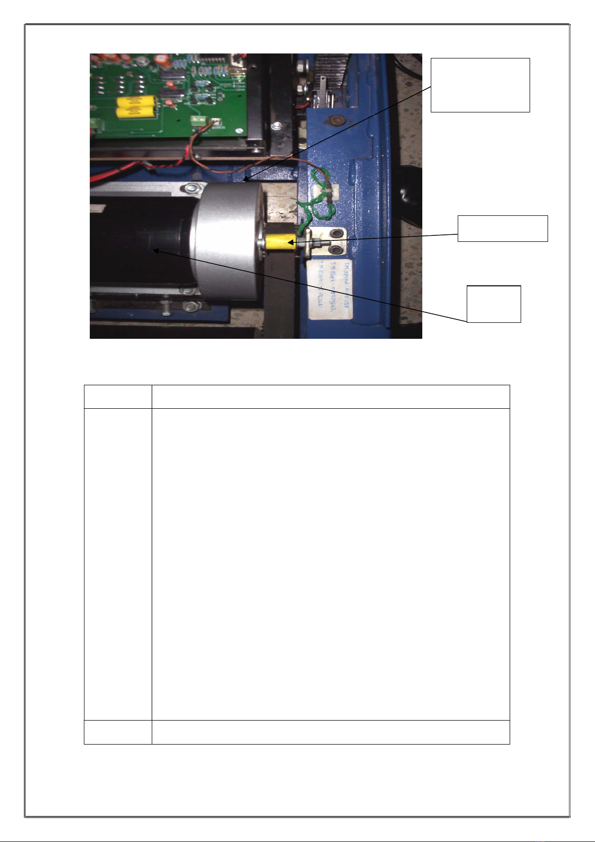
Problem
4.
Speed goes on increasing when we switch on the treadmill
(Uncontrolled speed)
Possible cause:
1. When the stress test is started and the program goes into the
first stage, the treadmill should reach a speed of 2.7 km/hr
gradually.
2. But if the speed goes on increasing continuously more than
2.7km/hr (uncontrolled), it means that the feedback path is not
getting completed.
Solution:
1) For this do following steps one by one till the problem gets solved.
a) Check sensor connector is properly connected. Ensure that it is
not loose also.
b) Check continuity of treadmill to STWIN amplifier cable, if needed
re-solder the same.
c) Remove the speed sensor wires & ensure that resistance of
speed sensor is nearly equal to 14 ohms.
d) Check the position of magnet on flywheel and ensure that
magnet is present on flywheel.
e) Ensure that the (d 41) LED on AC/DC drive is blinking.
2) If points 1/2/3 as mentioned above are correct and still this LED is
not blinking, change the AC/DC drive.
(1) This problem also occurs due to failure of IC 324 or IC
374 and LM339 on PCB 141.
Material
Req.
Sensor coil, AC/DC drive, silicon oil (200ml).

Rev 8, Dated 27-2-2018
11
Problem
5.
Fuse blows as speed goes on increasing.
Background:
1. In our treadmill, the magnetic ring acts as a speed sensor (Refer
fig 5). Our software takes feedback from treadmill to know the
actual speed.
a. If the actual speed is more than required by protocol, the
software sends signal to treadmill so as to reduce the
speed.
b. If the actual speed is less than the required by protocol,
the software sends signal to treadmill so as to increase
the speed (attain the required speed).
Possible Cause:
If the speed sensor is broken or not at appropriate position the
feedback will be zero and the PC will consider that the actual speed is
zero. Hence the PC will keep on increasing the speed of treadmill
resulting in large current drawn by ac/dc drive. This cumulative action
will result in blowing of the fuse.
Check that current limit in each stage is normal, If there is a problem in
ac/dc drive then it will take large current then normal in that case
blowing of the fuse may occur.
Solution:
Change the broken speed sensor or magnet if needed.
Material
Req.
Fuse, sensor coil, magnet, and ACDC drive, silicon oil (200ml).
Problem
6. Jerk in speed/Speed reduces as patient walks on treadmill.
Possible causes:
1. No silicon oil below conveyor belt.
2. AC/DC drive unable to provide sufficient current to dc motor.
3. Interference of DC choke radiation with speed sensor feedback.
(Wrong increased speed feedback to PC).
4. Conveyor belt might be loose.
Solution:
1. Add silicon oil (50-100ml)below the belt from both sides.
2. Here, run test treadmill software, increase the speed up to 10
km/hr in steps of 1 km/hr. And ask a person to walk on
treadmill. Here the actual speed is reducing; adjust
compensation trim pot (p1) slightly so that sufficient current is
supplied to dc motor (Refer Fig 9).
3. After trying above two points, if still speed reduces as patient
walks on treadmill, interchange the two wires connected to
choke.
Material
Req.
Silicon oil (200ml), sensor coil/ACDC drive.

Rev 8, Dated 27-2-2018
12
Problem
7. Elevation is correct but speed incorrect in protocol
Possible causes:
1. Treadmill and STWIN amplifier not connected on one and the
same phase.
2. Treadmill connected on UPS supply.(It should be on stabilizer)
Solution:
1. Note down (i) Earth to neutral voltage, (ii). Earth to line voltage,
for treadmill, PC and stwin amplifier by removing the 3-pin
power cord (Refer fig 11).
2. If the treadmill, computer, amplifier are connected on
one and the same phase, you should get the same voltage
measurements at all 3 points.
3. If these voltages are different at all 3 points, there is a
possibility that all the three equipments are not connected on
one and the same phase.
4. Another possibility is that all three equipments are not
connected on one and the same earthing.
5. Remove the treadmill from UPS supply and connect directly on
mains 230-volt ac supply.
6. Hence whenever you face such problem, first of all always check
the above said voltages even though all mains supply
connections are the same as done previously.
7. You can also refer the solution for problem no 3,4
Material
Req.
Sensor coil, TPC cable, ST-Win amplifier, silicon oil (200ml).
2) ELEVATION RELATED.
Problem
1.
No Elevation
Background:
1. In our treadmill the function of elevation is performed with the
help of ac/dc drive and ac motor.
2. To make treadmill understand when and to what degree it
should elevate, signals are given by the PC through our
software.
3. A feedback mechanism is established so that the protocol and
actual elevation match.
Causes:
1. Whenever there is no elevation then there is a problem in either
the AC/DC drive or ac motor, which elevates the treadmill.
2. The problem lies in the feedback mechanism.
3. The feedback mechanism consists of 10 k 10 turn pot, AC/DC
card and TPC cable.
4. If the treadmill does not elevate, then ac motor may be jammed
due to long inactive period of 2-3 months.
Solution:
1. Switch off treadmill, open the top cover, rotate shaft of the ac
motor manually by hand. In this way elevate the treadmill
nearly up to 3rd stage elevation.
Warning: Do not put any sort of oil at the shaft of ac motor to
make it free. This will burn the windings of the ac motor.
2. Whenever there is a no elevation do the following steps:
1) Run test treadmill program (Refer procedure 12) and
click appropriate buttons for speed increase and
decrease.
2) Observe the LED on the back panel of STWIN amplifier
3) If corresponding LEDs are glowing then do the next step.
But if the LED is not glowing then the problem lies with
STWIN amplifier or the calibration factors might be

Rev 8, Dated 27-2-2018
13
wrong.
4) Disconnect the treadmill to STWIN amplifier cable and
short pin 1 & 7 of the 15-pin d type connector (the place
from where you have disconnected the cable on treadmill
side) and check whether the treadmill is elevating.
5) If the treadmill is elevating then the problem most likely
lies on STWIN amplifier side.
This problem occurs due to
a. Low voltage below 180v
b. Due to shortage of limit switch pins
c. Failure of condenser(capacitor)
d. 10k pot settings got disturbed
Material
Req.
10 k 10 turn pot, STWIN amplifier, silicon oil (200ml).
Problem
2.
Treadmill runs smoothly for first couple of stages, after that it
elevates randomly.
Background:
1. The 10 k 10 turn pot acts like sensor for elevation feedback.
2. On the shaft of the pot a plastic wheel is mounted. This wheel is
engaged with plastic ring having teeth, which is mounted on pinion
(metallic rod to which pot is engaged).
3. As the treadmill elevates up or down, the pinion rotates
accordingly. This results in rotation of pot.
4. Depending on this rotation of the pot, the feedback voltage
changes.
Possible Cause:
If the engagement between pot and pinion gets misaligned, the pot
will not rotate properly and the feedback will not be proper. This will
result in wrong elevation or random elevation.
Solution:
Change 10 k pot if existing pot is not getting set. (Refer procedure
2, Changing of 10 K 10 turn pot, page- 26).
Material
Req.
10 k 10 turn pot. In amplifier, problem rise due to failure of IC 324 on
2K 20156, silicon oil (200ml).
Problem
3.
Treadmill stuck /elevates to its top position
1. Check treadmill manually by removing TPC cable.
2. Check treadmill manually from 15 pin connector on ac/dc drive. If
working, fine. If not working then remove AC motor’s connections
from acdc card and put in extension board to check AC motor.
3. Connections: Grey+BlackDOWN
Grey+RedUP
Warning: Do not put red and black simultaneously it will physically
burn the ac motor.
If motor is working then change AC/DC drive.
Possible cause: STWIN amplifier not working.
Solution:
1. Change the STWIN amplifier;
2. Recalibrate the treadmill check the treadmill through test
treadmill option.
3. If still problem persists, isolate the treadmill from PC and test
the same independently for elevation as given in procedure
‘Independent testing of treadmill’. (Procedure 1,page-26**)
4. If the problem still persists, replace AC/DC card.
Material
Req.
AC/DC Drive, AC motor, silicon oil (200ml).

Rev 8, Dated 27-2-2018
14
Problem
4.
On/Off switch (mcb) of treadmill trips down
Possible cause:
Due to sudden large spike or high voltage, ac/dc drive may be short-
circuited.
Solution:
1. Isolate the treadmill from PC by removing treadmill to STWIN
amplifier cable. Switch on treadmill.
2. If still mcb trips, change AC/DC drive.
Material
Req.
AC/DC Drive, silicon oil (200ml).
Fig 6. FRONT PANEL CONNECTIO
Problem
5.
Treadmill elevates properly up to 1
st
stage only and no further
elevation.
Possible cause:
Treadmill not calibrated.
Solution:
Calibrate the treadmill as per user manual.
10k 10 turn pot setting might get disturbed or it is faulty.
Material
Req.
10k 10 turn pot along with 33 t gear wheel, silicon oil (200ml).
FROM AC
MAINS
MCB
CHOKE
TO TPC CABLE
TO
EMERGEN
CY STOP
SWITCH
10 K 10
TURN
POT
AC MOTOR
CONNECTION

Rev 8, Dated 27-2-2018
15
Problem
6.
Treadmill elevates /de-elevates slightly
Possible causes:
1. AC/DC card not working.
2. Capacitor 33uf/440 volt becomes leaky/faulty.
3. Ac motor may be faulty.
Solutions:
1. Switch off treadmill; remove TPC cable from treadmill end.
2. Remove back cover of treadmill.
a. Switch ON the treadmill; short pin no. 1 & 7 of 15- pin d
type connector.
b. Here if the treadmill does not elevate up and the relay on
the ac/dc card is also not making any clicking/audible
noise, the ac/dc card is faulty and needs to be replaced.
c. The same is also applicable for de-elevation. Short pin
no. 1 & 8 of 15- pin d type connector.
d. Here if the treadmill does not come down and the relay
on the ac/dc card is also not making any clicking/audible
noise, the ac/dc card is faulty and needs to be replaced.
3. In continuation to above test, if the relay on the ac/dc card is
making any clicking /audible noise, and the elevation/de-
elevation is taking place by a very small amount, then the
33uf/440 volt capacitor need to be replaced.
4. So change the capacitor by a new one. This capacitor is to be
changed directly. It cannot be tested on multimeter or on 230-
volt ac supply alone. Check Input voltage to ACDC it should not
be less than 180 v.
5. If treadmill is elevating and de-elevating properly independently
from 15 pin d type female connector, but elevating or de-
elevating slightly in test treadmill or calibration program, then
STWIN amplifier needs to be replaced. First of all check 10k 10
turn pot setting.
6. Even after changing the capacitor, the elevation /de-elevation
does not takes place, the ac motor need to be checked.
7. For this, switch off the treadmill; remove mains 230-v supply to
treadmill. Mark the connection details of three wires according to
their position. (Color-coding cannot be mentioned because out of
three wires, 2 wires are green. And if these wires are
interchanged, instead of elevation, de-elevation will take place.
Here if treadmill is already at ground level, further de-elevation
will not take place and you will get confused) Isolate the three
wires coming from ac motor. Measure the resistance between all
pairs of these 3 wires. You should get resistance around 28
ohms. If you get zero resistance or infinite resistance, ac motor
is faulty and needs to be replaced.
How to check AC motor independently:
1. Remove three wires coming from AC motor to ACDC drive
2. Put grey wire in neutral and red wire on live for elevation up
3. Put grey wire in neutral and black wire on live for elevation down
Warning: Do not put red and black wire at a time, it will burn
motor.
Material
Req.
AC/DC drive, capacitor, ac motor, 10k pot, silicon oil (200ml).

Rev 8, Dated 27-2-2018
16
Fig. 7 AC/DC COMBINED CARD CONNECTION
Problem
7.
No medians and no heart rate.
Background:
1. In stress test, sometimes it happens that patient is connected to
stress test, and all the leads are displayed properly but there are
no medians.
2. In our stress test, heart rate is counted depending upon the
number of R waves appearing in QRS detect lead.
3. If this QRS detection lead has very low amplitude of R wave
(less than 0.4cm), then heart rate cannot be calculated.
Cause:
If heart rate is not calculated, then the medians will also be not
displayed.
Solution:
1. Change the QRS detection lead from menu option so that the Q
detection lead is with tall R wave.
2. Amplify the QRS detection lead.
3. Increase the gain. After doing any one of above three options,
wait till the heart rate settles to correct value. Once the heart rate
settles, click relearn button buttons 3 to 4 times so that the medians
get updated correctly.
Material
Req.
Software CD.
FROM SPEED
SENSOR
AC MOTOR
NORMALLY
SHORTED. Like fig
on page 26.
AC MAINS
DC
MOTOR
UPPER
LIMIT
SWITCH
LOWER
LIMIT
SWITCH
15 PIN
CONNEC
TOR
FROM
TPC
CABLE
FROM
10 K
POT

Rev 8, Dated 27-2-2018
17
Problem
8.
While coming down treadmill not stopping
Possible Cause:
Bottom limit switch might be loose. Because of this, when the treadmill
elevates it goes up but while coming down it does not stop. The bottom
switch does not operate; it must not be getting pressed. It might be out
of its original position, because of this 11t sprocket can get damaged
(Note: While fitting limit switch use plain and spring washer
from top side of the bolt and from bottom side use plain washer
spring washer and nut).
Solution:
1. Check the bottom limit switch position whether in alignment with
the treadmill.
2.
Make the limit switch tight if it is loose.
Material
Req.
Plain washer, spring washer, bolt nut for limit switch.
Problem
9.
Slow speed and slight elevation before 1
st
stage.
Possible causes: -
1. PC configuration less than P-III 550 MHz.
2. Treadmill not calibrated for speed and elevation.
3. Treadmill and amplifier, both not connected on one and the
same phase.
4. Problem in amplifier.
Solution:
1. If PC configuration is less than P-III 550 MHz such as Celeron,
this problem will occur. Hence always use PC configuration,
which is higher than P-III 550 MHz.
2. During speed calibration, at last stage, the computer tells us to
press any key when treadmill speed reaches to zero. Here if you
press any key before the speed reaches to zero, this slow speed
will occur in supine, standing, and hyperventilation stages.
Hence during speed calibration always wait till the speed
becomes zero in last stage.
3. If treadmill and amplifier, both are not connected on one and
the same phase, this problem may occur. Hence always ensure
that the treadmill and the amplifier, both are on same phase and
both should be connected on one electrical extension board.
4. If after checking all above possibilities, if still problem exists,
change the amplifier and re-calibrate treadmill for speed and
elevation.

Rev 8, Dated 27-2-2018
18
3) SOFTWARE RELATED.
Problem
1.
PC or ECG getting hanged while running software
Possible causes:
Following software are running at the background
1. Web shot wall papers
2. Quick Heal Antivirus with auto-protect On
3. Screen Saver
The sampling frequency of ST-WIN is 250 samples/seconds i.e.
samples are read after every 4 millisecond. Software has to perform
many tasks in 4 milliseconds, like reading data of 12 channels through
serial port, Display data in different format on screen, apply algorithms,
store data on hard disk, print online automatic reports and many more.
If applications other than ST-WIN like as listed above are running in the
background, they interrupt processing of ST-WIN Software and
problems like System Hanging, Traces Becoming Slow, Improper
Traces, Spikes on QRS Complex start coming. Such types of problems
may be seen with other softwares like Neurowin / Necropsy and Omni
watch. These softwares can be seen in the right side of the Task Bar,
near time display.
Solution:
For disabling these softwares, right click on the icon and select
disable.
1. Remove unnecessary files in startup
click on start-run type MSCONFIG-startup tab
2. Then restart PC
Material
Req.
Remove unnecessary files in startup.
Start: 1. RUN.
2. MS CONFIGURE
3. STARTUP and restart PC.( Software can be hanged due to
wrong reset procedure)
Problem
2.
Communication Error
Possible Cause:
1) Serial port connection open or short check continuity or re-
solder if needed
2) COM port not working.
3) COM port interface in the amplifier not working.
Solution:
1) Check connection and reconnect
2) Try by changing the Com port.
3) Replace MAX 232 IC and connect serial port cable to amplifier and
check for communication.
Material
Req.
MAX 232 IC, IC 374(u34)/STWIN amplifier.
Problem
3.
Noise in ECG when patient walks on treadmill or even if he
stands on treadmill
Possible Cause:
1. Treadmill is not grounded to earth properly.
Solution:
1.Check the first green wire from DC motor body is connected to
black box of ACDC card
2.Check whether the second green wire from DC motor body is
connected with earth wire of mains into ACDC drive
3.Check the earth wire from mains is connected to chassis. (Please
refer fig 12 for better idea of earthing).
Material
Req.

Rev 8, Dated 27-2-2018
19
Problem
4.
Error of DAO setup or error as ‘STWIN 98-mdb ‘file not found.
Solution For the softwares after version 3.74, we have observed that the old
DAO Setup is not sufficient. So we have developed new DAO setup
which is already been supplied with ST-Win Software. Install new DAO
setup wherever there is new installation or up- gradation.
Material
Req.
Software CD.
Problem
5.
Error as ‘STWIN 98-mdb’ file missing. When we install DAO Setup
for St-Win 3.74 from CD ROM, it works fine. But when we remove
the CD, then an error as ‘.mdb’ file missing comes.
Solution
While installing DAO Setup, it is taking the source path as default path.
That’s why when we install DAO Setup from CD ROM and remove the CD; it
can’t find required files from CD ROM.
For installing DAO Setup and NASAN Software, you are requested to
follow the steps as,
1. Install NASAN software from CD.
2. Copy DAO setup from CD to C:\progrm files\nasanstwin.
3. Install DAO setup from this folder.
Install other utilities from CD. St-Win 3.74 and onwards is developed on
“.net” platform which needs different DAO setup. This DAO setup is
provided with St-Win 3.74. To install this, one has to just double click on
DAO.exe.The above written procedure is also to be followed for new DAO
setup.
Material
Req.
Software CD.
Problem
6.
lead I is coming inverted
Solution There are two ways in which lead I may come inverted,
1) Lead I is derived from Lead II and Lead III (Lead II – Lead III). So
whenever lead II is coming as straight line then Lead I come
inverted. In such case we have to change the amplifier.
2) Doctors are comparing our Stress Test reports with BPL’s or others’
stand alone ECG machines. In stand-alone system, electrodes are
placed on limbs whereas in stress test we place electrodes on chest.
There is significant distance between chest and limbs, which causes
increase in resistance offered to signals. Hence there is strong
chance of getting difference between morphology of Stand-alone
systems and morphology of Stress test.
Material
Req.
Problem
7.
Spikes during the test due to which HR is more than actual
value.
Possible cause:
1) Earthing may not be proper (Refer fig 12).
2) Hard-disk may be less than 72000 rpm.
3) Sound drivers not installed properly or not
compatible with the system.
Solution:
1) Check whether earthing is proper or not.
2) Remove unwanted s/w like WEBSHOTS etc.
3) Disable unnecessary startup files.
Procedure for disabling.
Go to START menu and click on RUN icon.
Type ‘MSCONFIG’ and click startup menu bar.
Select unwanted items and apply.
4) Install the sound drivers properly and use compatible
drivers
Mat Req.

Rev 8, Dated 27-2-2018
20
4) MISCELLANEOUS
Problem
1.
Treadmill becomes non-functional again and again.
Possible Cause:
1. No Servo make voltage stabilizer is used for treadmill even
though the supply voltage is fluctuating.
2. Voltage Stabilizer is not stabilizing the voltage.
3. Type of Stabilizer is other than Servo.
4. There might be leakage current.
5. Problems due to slower configuration.
Solution:
1. Use 3.5 KVA Servo Stabilizer for treadmill.
2. Ensure that in spite of changes in supply voltage at mains, the
output voltage is stable. For this, change the analog meter
switch of stabilizer to INPUT mode, Connect digital voltmeter
(D.M.M.) to output of the stabilizer. Now you are observing input
voltage to stabilizer and output voltage of the stabilizer. Here
the out put voltage displayed on D.M.M. should not vary by
more than 2-3 volts even though the input voltage changes by
more than 10-20 volts.
3. If this output voltage to treadmill is also varying with changes in
supply voltage, the stabilizer needs to be repaired immediately.
4. There are different types of voltage stabilizers used for voltage
stabilization. One is the On-OFF type of stabilizer. Here
depending upon the input voltage range, the relay inside the
stabilizer operates to stabilize the output voltage. But this relay
operation generates a spike at the output. This spike creates a
problem to DC motor speed control circuit and hence the
treadmill stops working. Another type of stabilizer is SERVO
STABILIZER. This stabilizer has built-in servo- motor, which
rotates continuously with change in supply voltage. The shaft of
this motor selects the appropriate winding of the VARIAC so as
to stabilize the output voltage at 230 volts. Hence there are no
spikes in the output voltage of the stabilizer.
5. This SERVO type is recommended for treadmill.
Material
Req.
Problem
2.
10K 10-turn pot getting burned.
Solution 10K pot setting procedure is given below,
1) Remove the 15-pin TPC cable from Treadmill end.
2) Bring the treadmill down to ground level by shorting the pin no. 1 &
pin no. 8.
3) Unpack the gear assembly of 10K 10 turn pot.
4) Rotate the pot & set it to get voltage across brown & black wires as
950 mv To 960 mv.
5) Fix the gear assembly in achieved condition.
6) It will set the lower limit.
7) Make treadmill UP and DOWN 2-3 times to check 10 pot gear
assembly.
8) Pack the AC/DC Drive & top cover of Treadmill.
9) Calibrate Grade through software.
10) The upper limit will be set by software.
Check whether it is working properly or not
Material
Req.
10K 10-turn pot.
Table of contents
Other NASAN Medical Equipment manuals
Popular Medical Equipment manuals by other brands

Sirona
Sirona CEREC MC XL operating instructions

ResMed
ResMed Astral 150 Information and User Guide for Qualified Professionals

Welch Allyn
Welch Allyn KleenSpec 790 Series Directions for use

Verathon
Verathon BladderScan BVI 9400 user manual

Timago
Timago 7E-B5 user manual

Aesculap
Aesculap ELAN 4 Instructions for use/Technical description