©Ecoflo Wastewater Management Pty LtdIMNL-009-2024-01-09 Page 1
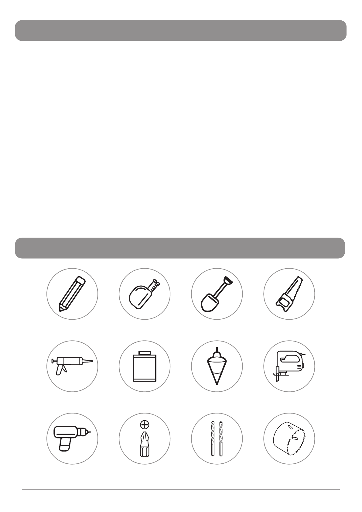
TOOLS REQUIRED
PVC
CEMENT
SILICONE
Marker Tape Measure Shovel Hand Saw
JigsawPlumb BobPVC CementCaulk Gun
Power Drill Philips Drill Bit Masonry and Brad
Point Drill Bits Hole Saw
Drill Bit
ITEMS REQUIRED (NOT INCLUDED)
Please check the packing slip to ensure everything has been delivered. If anything is missing, please
notify Ecoflo within 72 hrs of receipt.
You will need the following items to complete your installation.
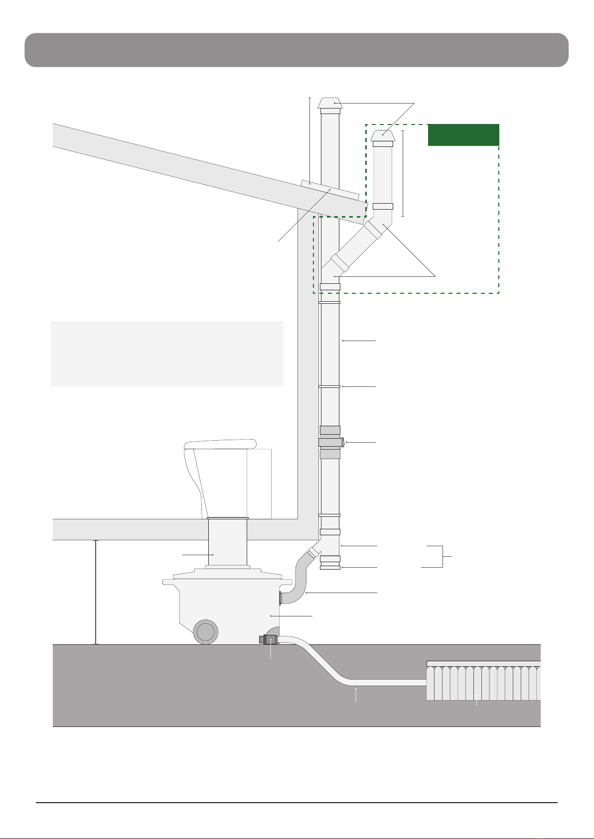
Vent items
• Wall brackets to fix the vent pipe to the building
• A length of 100mm DWV vent pipe to connect to the air exhaust (length depends on specific
installation)
• Dektite if DWV vent pipe will penetrate the roof
Leachate drain items (please check with your local authority)
• Ø100mm Agricultural pipe
• 1.5m x 0.5m Synthetic or Hessian geotextile mat
• 50mm PVC pipe to connect the hose to the agricultural pipe
• 0.30m³ 20mm Aggregate
A vent kit and drain kit are available to purchase separately from Ecoflo.