2
Mini Clubman 2008-2010
Precautions
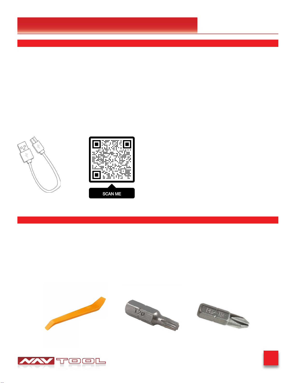
What’s In The Box
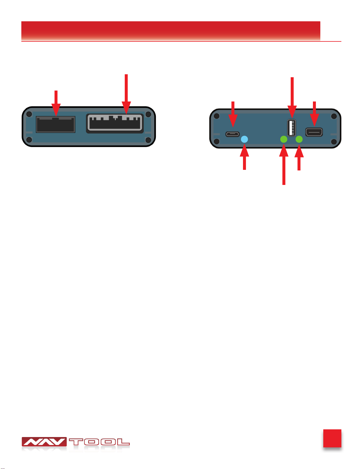
Interface Connectors Description
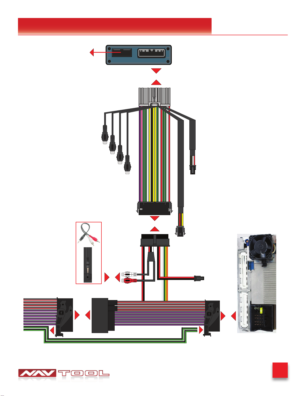
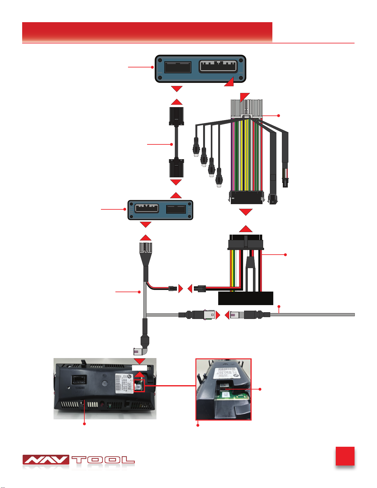
Universal Harness Description
NEED HELP?
WELCOME
IMPORTANT WARNING
This product includes instructions for
installation, which must be carefully
followed. The instructions are worded
in such a manner to assume that
the installer is capable of completing
these types of electronic installations.
Suppose you are unclear about what
you are instructed to do or believe
you do not understand the instruc-
tions to complete the installation
properly and safely. In that case, you
should consult a technician who has
this knowledge and understanding.
Failure to follow these instructions
carefully and install the interface as
described could cause harm to the
vehicle or safety systems on the
vehicle. Interference with specic
safety systems could cause damage
to persons as well.
Open the camera app on your smart-
phone and point your rear camera at
the QR-Code to scan it. Finally, tap
the pop up banner to open support
website.
Quick Connection Guide
Installation Instructions
Testing and Settings
3
4
5
6
7-9
10-18
19-22
Installation Instructions
Connect Rear Screens With AV Input
Connect Rear Screens With HDMI Input
24
25
Extra Details
Vehicle Reassembly Checklist 23
User Manual
User Manual for Consumers C1-C3
Print pages C1-C3 and give them to the customer