Navpixel NPD1236-12 User manual

Page 1
Navpixel™ USER MANUAL
NPD1236-12” IP-65 Marine Display
NDP1555- 15” IP-65 Marine Display
NPD1744- 17” IP-65 Marine Display
NPD1954- 19” IP-65 Marine Display
NPD2115- 21.5” IP-65 Marine Display
(1st Edition 9/15/2010)
All information is subject to change without notice.

Page 2
RECORD OF REVISION
Version and Date Description Remark
Sep.15 2009 Preliminary Release

Page 3
TABLE OF CONTENT
RECORD OF REVISION ........................................................................................................ 2
TABLE OF CONTENT....................................................................................................... 3
1.0 INTRODUCTION............................................................................................................ 7
2.0 CONTROL AND FEATURES............................................................................................. 8
3.0 INSTALLATIONS ............................................................................................................ 9
4.0 TOUCH DRIVER INSTALLATIONS.................................................................................. 15
5.0 OSD OPERATIONS....................................................................................................... 35
6.0 TECHNICAL SPECIFICATION........................................................................................ 51
7.0 MAINTENAINCE AND TROUBLESHOOTING................................................................... 61

Page 4
IMPORTANT INFORMATION
EMC conformance
All Navpixel equipment and accessories are designed to the best industry standards for
use in the recreational marine environment. The design and manufacture of Navpixel
equipment and accessories conform to the appropriate ElectroMagnetic Compatibility
(EMC) standards, but correct installation is required to ensure that performance is not
compromised.
Waste Electrical and Electronic Equipment Directive
The Waste Electrical and Electronic Equipment (WEEE) Directive requires the recycling
of waste electrical and electronic equipment. Whilst the WEEE Directive does not apply
to some of Navpixel’s products, we support its policy and ask you to be aware of how to
dispose of this product.
The crossed out wheelie bin symbol, illustrated above, and found on our products
signifies that this product should not be disposed of in general waste or landfill. Please
contact your local dealer, national distributor or Navpixel Technical Services for
information on product disposal.
Restriction of the use of certain Hazardous Substances
This product uses components that comply with the requirements of the Restriction of
the use of certain Hazardous Substances (RoHS) Directive 2002/95/ EC.
Warranty
To register your new Navpixel product, please go to:
www.navpixel.com.
It is important that you complete the owner information to receive full warranty
benefits, including notification of software updates if they are required.

Page 5
Packing List
Before installation, please ensure the following items have been shipped:
z1 x Navpixel Series Marine Display
z4 x Mounting bracket lugs and 4 stainless steel threaded studs
z1 x Power Cable (5000 mm)
z1 x VGA Cable (3000 mm)
z1 x CD for User Manual and Touch Driver
z1 x Printed Flush Mount Template
z1 x Printed User Manual
z1 x AC/DC Adaptor for model NPD1236/1555-(EGAW & ETAW)-G011
NPD1744/1954/ 2115-(EGAW & ETAW)-H011
If any of these items should be missing or damaged, please contact your distributor
or sales representative immediately.

Page 6
Ordering Information
Model Number & Description
NPD1236-EGAW-G01
12” Sunlight readable LCD, Optical bonding AR glass, 9~36V DC wide range input power
NPD1236-EGAW-G011
12” Sunlight readable LCD, Optical bonding AR glass, 9~36V DC wide range input power, with power adaptor
NPD1236-ETAW-G01
12” Sunlight readable LCD, Optical bonding SR touch, 9~36V DC wide range input power
NPD1236-ETAW-G011
12” Sunlight readable LCD, Optical bonding SR touch, 9~36V DC wide range input power, with power adaptor
NPD1555-EGAW-G01
15” Sunlight readable LCD, Optical bonding AR glass, 9~36V DC wide range input power
NPD1555-EGAW-G011
15” Sunlight readable LCD, Optical bonding AR glass, 9~36V DC wide range input power, with power adaptor
NPD1555-ETAW-G01
15” Sunlight readable LCD, Optical bonding SR touch, 9~36V DC wide range input power
NPD1555-ETAW-G011
15” Sunlight readable LCD, Optical bonding SR touch, 9~36V DC wide range input power, with power adaptor
NPD1744-EGAW-H01
17” Sunlight readable LCD, Optical bonding AR glass, 9~36V DC wide range input power
NPD1744-EGAW-H011
17” Sunlight readable LCD, Optical bonding AR glass, 9~36V DC wide range input power, with power adaptor
NPD1744-ETAW-H01
17” Sunlight readable LCD, Optical bonding SR touch, 9~36V DC wide range input power
NPD1744-ETAW-H011
17” Sunlight readable LCD, Optical bonding SR touch, 9~36V DC wide range input power, with power adaptor
NPD1954-EGAW-H01
19” Sunlight readable LCD, Optical bonding AR glass, 9~36V DC wide range input power
NPD1954-EGAW-H011
19” Sunlight readable LCD, Optical bonding AR glass, 9~36V DC wide range input power, with power adaptor
NPD1954-ETAW-H01
19” Sunlight readable LCD, Optical bonding SR touch, 9~36V DC wide range input power
NPD1954-ETAW-H011
19” Sunlight readable LCD, Optical bonding SR touch, 9~36V DC wide range input power, with power adaptor
NPD2115-EGAW-H01
21.5” Sunlight readable LCD, Optical bonding AR glass, 9~36V DC wide range input power
NPD2115-EGAW-H011
21.5” Sunlight readable LCD, Optical bonding AR glass, 9~36V DC wide range input power, with power adaptor
NPD2115-ETAW-H01
21.5” Sunlight readable LCD, Optical bonding SR touch, 9~36V DC wide range input power
NPD2115-ETAW-H011
21.5” Sunlight readable LCD, Optical bonding SR touch, 9~36V DC wide range input power, with power adaptor
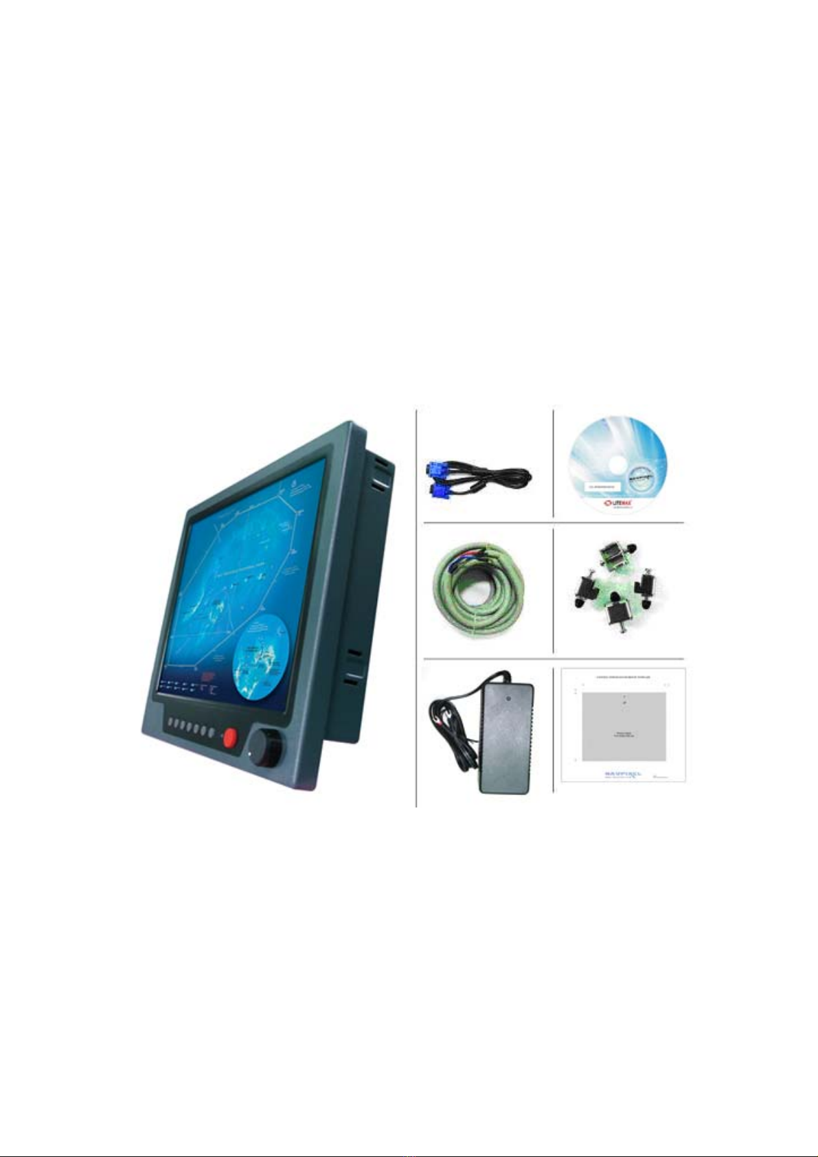
Optional Accessories
810130001000 VGA Cable 3000mm. D-SUB15P TO D-SUB 15P
810650005110 Power Cable, DC, 5000mm, TERMINAL TO OPEN, 14AWG*2C

Page 7
1.0 INTRODUCTION
About Navpixel™ Marine Display
Navpixel™ Series Marine Display, the high-performance, equipped with optical bonding
AR glass or sunlight readable touch monitor, is specially engineered to survive the most
demanding applications. You will soon become familiar with the quality difference in
this bright sunlight readable (0.5 to 1,000 nits) monitor.
The range of Navpixel Sunlight Viewable Marine Displays has been developed to be used
as part of an integrated marine navigation system or within an entertainment system.
The displays, available in several sizes, are designed to be waterproof and suitable for
use above or below decks.
The Navpixel™ Series Marine Display sunlight readable monitor handles a wide-range of
extreme environments making it the industry choice for mobile applications. Housed in a
milled billet aluminum case, the slim-profile Navpixel™ Series Marine Display is light
weight and watertight. Front-mounted controls and the touch screen make the industrial
rugged monitor user-friendly. We have incorporated the latest optical engineering to
achieve optimal viewability in all lighting conditions, including direct sunlight. The
Navpixel™ Series Marine Display’s power efficient, low heat design results in increased
reliability and longevity required for mission critical deployment.
This handbook contains important information on the installation, operation and
maintenance of the Navpixel Sunlight Viewable Marine Display range which is intended
for use in the recreational marine market and covers all models.

Page 8
2.0 CONTROL AND FEATURES
Your Navpixel Sunlight Viewable Marine Display has the following controls and features:
Front View
Remarks: The PIP function is only available for NPD1744, NPD1954 and NPD2115 model
Back View
Remarks: Only DVIx1 and VGAx1 for NPD1236 and NPD1555 model

Page 9
3.0 INSTALLATIONS
It is important that your new display is installed and operated in accordance with the
instructions provided in this handbook. Failure to do so could result in poor product
performance and may invalidate your warranty.
When planning the installation the following points must be considered:
• Your Navpixel display is sunlight viewable and visible in direct sunlight..
• If temperatures exceed the normal temperature operating range the display could
overheat and begin to blackout due to the limitations of TFT LCD technology.
• In order to minimize the chances of a malfunction, the following precautions should be
taken during installation:
• The display should be installed in an area where there is proper and adequate
ventilation (min. 15cm clearance) . If it is possible to cool the area behind the
display, it will significantly reduce the risk of a malfunction.
• The display should be mounted at an angle to the sun. We do not recommend
mounting the unit in a flat plane, which increases the surface area exposed to the
sun and leads to increased heat absorption.
IMPORTANT: Your Navpixel display is only waterproof from the front. To maintain
watertight integrity the display must be flush mounted ensuring that the rear casing is
enclosed in a watertight enclosure.
The Navpixel™ Series Marine Display is designed to be mounted in two configurations:
VESA75 / VESA100 MOUNT
The Navpixel™ Series Marine Display is designed compatible with VESA75 and VESA100
mount. By installing the monitor with this kit, the user can adjust the viewing angle to
improve viewability in changing environments. This mounting system has proven to be
successful in supporting an extreme amount of weight in high vibration and
difficult-mount applications.
The back of the monitor includes mounting points that you can use to mount the monitor
as your installation requires.

Page 10
Mounting holes on the Navpixel™ Series Marine Display allow the monitor to be mounted
by rear mounted using VESA75 or VESA100 mount
PANEL (Flush) MOUNT
For installation, there are four tapped mounting holes on the two sides of the unit’s
panel. The mounting hardware packet is included with the product accessories in the
shipping box. This packet includes four (4) stainless steel threaded studs, 3.2 cm and
four (4) mounting lock nuts.
Your monitor can be installed using the mounting lock nuts (supplied) in the vertical
keyways. Make sure that both brackets are in the same orientation.
Preparing the installation site
1. Select an installation site that has sufficient space behind for cable connections and
ventilation.
2. Tape the supplied flush mount template in the required position.
3. Using a jigsaw, carefully remove the shaded portion of the template.
4. Using a suitable file, smooth the edges of the aperture.

Page 11
Installing the display
1. Carefully insert the monitor into the aperture, ensuring that the gasket on the rear of
the fascia lays flat against the aperture edge.
IMPORTANT: The gasket must lay flat against the aperture edge to ensure watertight
integrity.
2. Place the mounting bracket lugs into the keyways and move them to the rear, securing
the bracket to the monitor.
Note: The mounting brackets can be used in either the horizontal or vertical keyways as
required.
3. Using a suitable screwdriver, tighten the mounting bracket screws to secure the
monitor in position.
4. Connect all cables as required - see “Rear connections” below.

Page 12
Rear connections
Remarks: The photo above will differ for different model
The rear connectors are:
1. FUSE
2. Power Input
3. DVI-1 Input
4. DVI-2 Input (N/A for NPD1236 & NPD1555)
5. VGA-1 Input
6. VGA-2 Input (N/A for NPD1236 & NPD1555)
7. CVBS-1 Input (Composite Video) for AV input
8. CVBS-2 Input (Composite Video) for AV input
9. CVBS-3 Input (Composite Video) for AV input
10.RS232 Input
11.USB for Touch control (option)
Planning the installation
Before you install your display, the following points should be considered:
• Power requirements.
• Display location and mounting options.
• Additional accessories, e.g. keyboard or speakers.
Power requirements
Your Sunlight Viewable display is designed to run on boat’s power systems, with AC/DC
adaptor Navpixel series are equipped with 9~36V DC wide range power input.
For power connection please make sure the power cable is tightly connected by two
screws of the terminal block.
The output pin of AC/DC adaptor should be checked and make sure the polarity of
voltage is connected properly.
Grounding the display
It is important that an effective radio frequency (RF) ground is connected to the display.
You must ground the display by connecting the drain wire (shield) of the power input
cable to the nearest ground point of the boat’s RF ground system.

Page 13
Display location and mounting options
Your display can be mounted using the flush mounting kit supplied. Navpixel
recommends that you power the unit and select a suitable mounting location prior to
installing the display.
When planning the display location, the following points should be considered to ensure
safe, comfortable and reliable operation:
• Convenience- the mounting location should be easily accessible to allow operation of
the controls and should enable easy viewing of the display.
Power connections
The power connection to the display should be made at either the output of the battery
isolator switch, or at a DC power distribution panel. Navpixel recommends that power is
fed directly to the display via its own dedicated cable system and MUST be protected by
a thermal circuit breaker or fuse, fitted close to the power connection. If you do not
have a thermal circuit breaker or fuse in your power circuit, you MUST fit an in-line
breaker or fuse to the positive (red) lead of the power cable.
• Installation angle- the display should be mounted at an angle. Mounting it in a flat
plane is not recommended due to increased heat absorption.
• Viewing angle - this LCD has been chosen to give the very best performance, including
viewing angle. However, the contrast and colors seen on all LCD displays vary slightly
with viewing angle.
• Environment - to prevent overheating, do not restrict airflow at the rear of the display
unit; If the space behind the display is air conditioned or cooled by a fan, it will help in
keeping the unit’s temperature down when mounted in direct sunlight.
FAILURE TO ADEQUATELY VENTILATE THE UNIT COULD INVALIDATE YOUR WARRANTY.
The display should be protected from physical damage and excessive vibration. Although
the display unit is waterproof from the front when installed correctly, it is good practice
to mount it in a protected area away from prolonged and direct exposure to rain and salt
spray. DO NOT place the display near to a heat source.

Page 14
Typical Installation Diagram
Remarks: The real installation diagram above is only for reference and will differ for different kind of
customer’s applications

Page 15
4.0 TOUCH DRIVER INSTALLATIONS
Both AR glass and Resistive touch screen solutions are used for our products. If you
have a customized or tailored product, please check the specifications in this
manual or provide us your third-party specifications.
Resistive Touch Screen
It generally uses a display overlay composed of layers, each with a conductive
coating on the interior surface. Special separator “dots” are distributed evenly
across the active area and separate the conductive interior layers. The pressure
from using either a mechanical stylus or finger produces an internal electrical
contact at the “action point” which supplies the controller with vertical and
horizontal analog voltages for data input. The resistive touch screens are anti-glare
to reduce reflective shine intensity, which will slightly diffuse the light output
throughout the screen. Resistive technology activation can be initiated by; a gloved
hand, fingernail, mechanical stylus or an ungloved finger.
Resistive Touch - Brief Specifications
Subject Details
Input Method Finger & Stylus Finger & Stylus
Touch Stylus Touch Stylus
Gloved Hand
Touch Activation Force 0.10 - 0.80N (10 - 80g)
Insulation Resistance ≧20MΩ/25V(DC)
Light Transmission > 80%
Operating Temperature -10°C ~ +70°C
Storage Temperature -40°C ~ +80°C
Humidity (Operating) 20%RH ~ 80%RH
Surface Hardness ≧3H
Durability 35,000,000 times
This touch panel controller provides the optimistic performance of analog resistive
touch panels for 4 wire, 5 wire and 8 wire models. It communicates with PC system
directly through RS232, PS/2 or USB connector. Users can see how superior the
design is in sensitivity, accuracy and friendly operation. The touch panel driver
emulates mouse left and right button function and supports operation systems
including Microsoft Windows 95 / 98 / ME /NT4 / 2000 / XP / XP Tablet PC Edition,
Windows CE 2.12 / 3.0 / .NET, Linux, iMac and DOS.
Installing Software
TouchKit is software, which contains drivers of the touch panel controllers for the
specified communication connectors, RS232, PS/2 and USB, and the other two
utilities:
· Touch Tray support
This is utility for emulating the right and left button of mouse through controlling
touch panel. Users can toggle between right or left mouse buttons by this utility.
· Configuration support
The calibration and draw test of touch panel are done by this utility. Besides,
users can add or remove for new RS-232, PS/2 or USB touch panel devices.
Follow these steps to install TouchKit.

Page 16
1. Put the TouchKit CD to CD-ROM.
2. Change directory to Win9X_ME
3. Double click the Setup.exe, then windows starts to run the installation program.
Notice that do not plug the USB controller on the system before the installation has
been finished.
4. Just click [Next >] button to continue installation.
5. Then check the check box if PS/2 touch controller is to be installed. The default
is unchecked. Then Press [Next >] to continue installation.
System will give you a warning, if users check the PS2AUX check box,
6. Choose the setup type that best suits your needs. There are two TouchKit
accessory utilities for choosing, Rotation Monitor Utility and Shutdown Utility.
Users can install the utility they want by checking the box. Then Press [Next >]
to continue installation.

Page 17
7. Select the appropriate folder where set-up files will be installed. Then Press
[Next >] to continue installation.
8. Then type in the name of program folder for TouchKit or press [Next >] to
continue. There will be a default name for it.
During driver installation, the setup program will scan COM port for RS232 Touchkit
controller. Once the controller was scanned, the setup program will display a dialog
as
Click Yes to add the controller on the specified COM port automatically.
9. Windows is copying files to disk and the setup is complete. It will request re-boot
computer. Press [Yes >] to re-boot immediately or [No >] to re-boot later. The
installation will not be finished until system re-boot.

Page 18
10. Setup is complete. After TouchKit installation, the USB device will be found
automatically as soon as it was plugged into the computer. Then users can see
the new device on the application program window. And, the program will remove
the USB Device automatically as soon as it was unplugged. ( USB device is not
supported for Windows95 )

Page 19
Configuration Utility and Right Button Emulator
There are five property pages in TouchKit utility, and they are General, Setting,
Edge coefficient, Monitors and About. Each property page contains different
functions for users to do the adjustments. Therefore, users can easily manage all the
TouchKit controllers through TouchKit utility.
General
General property page contains the functions of language selection, devices add/
remove, 4 points calibration, Draw test and Advanced.
<Language>
TouchKit supports multi-language user interface. Users could select native
language that is compatible to operation system support. For example, if the
operation system is a traditional Chinese version, users could see the normal
display words under the traditional Chinese and English mode. There are ten
different languages, English, Traditional Chinese, Simplified Chinese,
French, Spanish, German, Japanese, Italian, Korean and Dutch supported in
this feature of TouchKit.

Page 20
Select the compatible language first or users may not see the normal display of each
button.
<Add> / <Remove>
Please check the touch panel devices (including its controller) are equipped well,
then click [Add] button to add all of those RS-232 and PS/2 devices to the Panel
List dialogue box.
There is one devices found. Press [Yes] to continue.
The controller is displayed on the Panel List box. Users can get the information
of interface, type, firmware version and baud rate for each controller.
Select one device after added more than one device at the panel list window.
The one selected will activate the panel, and remember to do the calibration
before starting to use touch panel.
This manual suits for next models
24
Table of contents