__________________________________________________________________________________________________________________________________
EuropeanSafetySystemsLtd. Impress House, MansellRoad, Acton, LondonW37QHsales@e2s.com Tel:+44 (0)2087438880
www.e2s.com Fax:+44 (0)2087404200
DocumentNo. IS2427-PIssue B17-04-02 Sheet2of 4
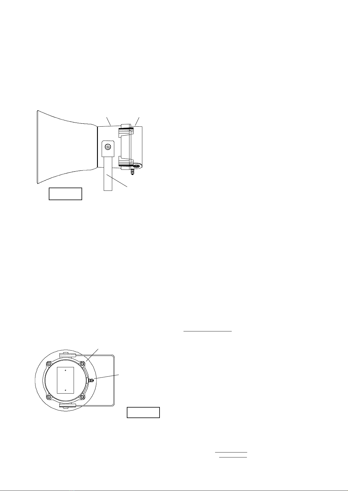
TheSontelsshouldbesecurely boltedtoasuitablesurface
usingthe7mmdiameter boltholesinthe stainlesssteelU
shapedmountingbracket(see figure1). Theanglecan then be
adjusted in the direction thatthe sound is primarily required to
cover. Thiscan beachieved by looseningthetwolarge bracket
screws in the side of the unit, whichallow adjustment in steps
of18°.On completion of the installation thetwolarge bracket
adjustment screws onthe sideof theunit must befully
tightenedto ensurethat theunit cannot moveinservice.
7) SafetyWarning (ElectrostaticHazard)
The acoustic horn sectionis made of ABSPlastic,thereforeto
avoidapossibleELECTROSTACTIC CHARGEthe unitmust
only be cleanedwith a damp cloth.
8) Access totheFlameproofEnclosure
Inorder to connect theelectrical supply cableandthe
telephonelinecabletotheSontelit isnecessarytoremovethe
flameproof cover togain accessto theflameproof chamber. To
achieve this remove thefour M6 hexagonsockethead screws
(seefigure 2)and withdraw theflameproof covertaking
extremecarenottodamagetheflameproofjointsin the
process.
Notethefour M6screwsareClassA4-80stainlesssteel
andonlyscrewsof thiscategorycanbeused on these
Sontels. Itis thereforeimportant that thesescrews and their
springwashersarekept in a safe place duringinstallation.
Oncompletionof thecable wiring installationtheflameproof
jointsshould be inspectedto ensurethat theyarecleanand
thatthey havenotbeendamagedduring installation.Also
checkthat theearthbonding wirebetween thetwocasting
sectionsissecureandthe‘O’ringseal isinplace.When
replacingtheflameproof cover casting ensurethat itis square
withthe flameproof chamber castingbefore inserting. Carefully
push thecoverin placeallowing timefor theair to be expelled.
Only afterthecover is fullyin placeshould the fourM6
StainlessSteelA4-80coverbolts and theirspringwasherbe
insertedand tighteneddown. If the coverjamswhile it isbeing
inserted, carefully remove it andtry again.Never use thecover
boltsto force the cover intoposition.
9) PowerSupplySelection
Itis important that asuitable powersupplyisused torunthe
Sontels.
The followingtableshowstheinputcurrent taken by the
various units:-
UnitTypeInputInputMax.
VoltageCurrentI/PVolts
BExTS110D230VAC56mA264V
BExTS110D110VAC93mA121V
BExTS110D115VAC110mA126V
The input currentwillvaryaccordingtothe voltage inputlevel
and the frequencyofthetoneselected.The current levels
shown abovearefor the 440Hz Continuoustone@nominal
input voltage.Theunitshaveaswitching voltageregulator
circuit andthereforethe input current levelwill decrease
slightly astheinputvoltagein increasedand willincrease
slightly astheinput voltageisreduced.
The abovetable also showsthemaximum voltagesat which
the sounderscanbe operated.
10) CableSelection
Whenselecting the cable size consideration mustbegivento
the inputcurrentthateach unit draws(seetable above), and
the length ofthe cableruns.
SAFETY WARNING: IfthehighoutputBExTS110Dunitsare
used athighambienttemperatures,i.e. over+40ºC, then the
cable entrytemperature mayexceed +70ºCand therefore
suitable heat resistingcablesmustbeused, witharated
service temperatureofat least 95ºC.
11) Earthing
The Sontelunits mustbeconnectedtoagood quality earth.
The unitsareprovidedwithinternal and externalearthing
terminalswhicharebothlocatedonthe terminalchamber
sectionoftheunit (seefigures 2and3).
Figure 1
PleaseseeSafetyWarning
in Section7ofthismanual
Chamber
Cover
Terminal


