Cetrek Propilot 725 User guide

-1-
PROPILOT 725 INSTALLATION & SERVICING MANUAL
Welcome
All of us at Cetrek would like to welcome you to the world of
Cetrek Propilot Systems.
Your Safety THE USE OF AN AUTOPILOT DOES NOT AVOID THE
NEED FOR NORMAL WATCHKEEPING.
EMC Directive 89/336/EEC
This product has been designed to be compliant with the
above Directive.
Maximum performance and compliance with the EMC
Directive can only be ensured by correct installation. It is
strongly recommended that the installation conforms with
the following Standards:
SMALL CRAFT - ELECTRICAL SYSTEMS:
a) ISO 10133 - Extra Low-Voltage DC Installations
b) ISO 13297 - Alternating Current Installations (Draft)
ISO- International Standards Organisation
The information contained in this manual is believed to be accurate at
the time of going to print but no responsibility, direct or consequential,
can be accepted by Cetrek Ltd for damage resulting from the use of
this information. Cetrek Ltd reserve the right to make changes
without notice to any of its products. © Cetrek Ltd 1996
807-252-10-96

-2-
PROPILOT 725 INSTALLATION & SERVICING MANUAL
CONTENTS
THE SYSTEM ................................. 5
System Accessories ............................ 5
A Brief Overview ............................. 5
INSTALLING YOUR PROPILOT 725 ................ 7
Before you Start .............................. 7
Suggested Procedure .......................... 7
Distribution Box .............................. 8
Compass Sensor ............................. 8
Autopilot Control ............................. 9
Rudder Feedback Unit ......................... 9
Drive Units ................................ 10
Big Ship Links .............................. 11
Good Wiring Practice ......................... 11
Connecting the Autopilot ...................... 13
INSTALLATION SCHEMATIC ..................... 14
INSTALLING OPTIONAL EQUIPMENT ............. 16
Cetrek Equipment ........................... 16
Navigators ............................... 16
NMEA 0180 ............................... 18
NMEA 0182 & 0183 .......................... 18
NMEA 0183 ............................... 18
Windvane Equipment ......................... 19
Gyro Equipment ............................ 19
PROPILOT 725 FRONT PANEL (KEY) FUNCTIONS .... 20
INSTALLATION SETTINGS ...................... 22
Rudder Phasing ............................. 22
Motor Phasing .............................. 22
Rudder Feedback Unit Offset .................... 23
Compass Alignment .......................... 23
Reset .................................... 23
To Exit Installation Settings ..................... 23
Compass Variation ........................... 24
Compass Damping........................... 24

-3-
PROPILOT 725 INSTALLATION & SERVICING MANUAL
Settings for Optional Equipment .............. 24
Windvane Interface Format ..................... 24
Wind Trim ................................. 25
Navigator Interface Format ..................... 25
Navigator Gain ............................. 25
External Alarm .............................. 26
Gyro Compass Control ........................ 26
Gyro Type or Gyro Ratio ....................... 27
CONFIGURING YOUR PROPILOT 725 ............. 28
The Settings Explained ...................... 28
Counter Rudder ............................. 28
Trim ..................................... 29
Rudder Ratio Gain ........................... 29
Rudder Deadband ........................... 30
Rudder Limit ............................... 30
Max Turn Rate .............................. 30
Power Steer Gain ............................ 30
Auto-deviation ............................. 31
Preset Configurations ....................... 31
Installing a Preset Configuration .................. 32
Adjusting Individual Configuration Settings .......... 33
SEA TRIALS ................................. 34
Checks at the Dockside ........................ 34
Checks at Sea .............................. 35
Automatic Deviation Correction ............... 36
SYSTEM DESCRIPTION ......................... 38
Block Diagram of Distribution Box ................ 38
The Distribution Box in Detail ................... 38
Fuses and Maximum Ratings .................... 38
Changing Software Eproms ..................... 39
Switches .................................. 39
TROUBLESHOOTING GUIDE .................... 41
General Principles and Cautions .................. 41
Faults .................................... 41
ERROR AND FAULT MESSAGES .................. 44
INDEX

-4-
PROPILOT 725 INSTALLATION & SERVICING MANUAL
The System

-5-
PROPILOT 725 INSTALLATION & SERVICING MANUAL
The System
THE SYSTEM
A basic system consists of the following:
•aDistribution Box (930 618) to collect, process and output
information.
•aCompass Sensor (930 577) to provide heading information.
• an Autopilot Control (930 725) for the helmsman to control
the autopilot.
•aRudder Feedback Unit (930 807) to provide rudder position
information.
The system also requires a Drive Motor (hydraulic or mechanical)
to activate the vessel's steering system.
SYSTEM ACCESSORIES
Your system may have some of these accessories as well:
• Dodge and Course Change remote controls.
• Power steer remote controls.
• Rudder Position Indicators and Repeaters.
• Compass Repeaters.
• External Audible Alarms.
• Windvane Sensors.
•ANavigator.
•AGyro Compass.
•Asecond station Autopilot Control.
A Brief The Distribution Box is the heart of the system and everything
Overview connects to this. It contains the computer section that reads the
data from the sensors, i.e. the rudder position from the Rudder
Feedback Unit, the vessel's heading from the Compass. It reads
the helmsman’s orders from the Autopilot Control or a
Navigator, then calculates, using the sea state and configuration
settings and moves the rudder, via the Drive Motor to maintain
a course.

-6-
PROPILOT 725 INSTALLATION & SERVICING MANUAL
Installing your Propilot 725
Hole positions 113 x 238 mm (4.45" x 9.37")
Cut-out for back 110 x 237 mm (4.33" x 9.33"), corners 13 mm (0.51") x 45º
NOTE: Also allow adequate clearance for cable connections to ensure cables
are not unduly stressed.
930 618 Distribution Box Dimensions
Propilot 725 Dimensions

-7-
PROPILOT 725 INSTALLATION & SERVICING MANUAL
Installing your Propilot 725
INSTALLING YOUR PROPILOT 725
Before you Before commencing the installation of your new pilot please carry
Start out the following initial checks:
• that the correct items have been delivered ?
• that the units are undamaged ?
• that the correct voltage drive unit has been supplied ?
• if using a Mechanical Drive Unit, that the correct chain and
sprocket is available ?
• if you are using a hydraulic pump, that you have the correct
size fittings available to connect the pump ?
• that you have the correct type of hydraulic fluid to top up the
steering system once the pump is installed ?
• that you have a power cable of a suitable gauge to supply
power to the system?
• that you have a Circuit Breaker of suitable size for your
system?
If you find an error please contact the supplier of the product
immediately.
Before the drilling or cutting of any holes takes place, please
consider the exact location and cable routing that is required for
each unit. Please read this installation section and any installation
information supplied with your units before you install the
system.
Suggested We suggest that the following procedure will allow you to install
Procedure the system encountering the least problems.
• Read this section then select the best positions for the units.
• Install the Distribution Box.
• Install the Autopilot Control and route the cable to the
Distribution Box.
• Install the Compass Sensor and route the cable to the
Distribution Box.
• Install the Rudder Feedback Unit and route the cable to the
Distribution Box.
• Install the drive unit. Route the cable to the Distribution Box.
• Route the light and heavy duty power supplies to the
Distribution Box.
• Then proceed to connect all the cables to the Distribution Box
as per the Installation Schematic.
Finally:
• Connect the light duty supply fused at 5 amps.
• Connect the heavy duty supply, see the Drive Unit
Caution!
All exposed moving
parts must be
sufficiently guarded to
prevent accidental
damage to persons or
clothing

-8-
PROPILOT 725 INSTALLATION & SERVICING MANUAL
Installing your Propilot 725
information for fuse ratings.
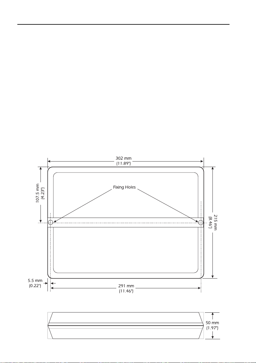
Distribution This is the heart of the system and must be installed in a DRY,
Box accessible position.
Ideally the box should be positioned so that the heavy duty
power supply cables from the batteries to the distribution box
and from the distribution box to the drive unit are kept to a
minimum length. This is particularly important on sailing
vessels where often you are operating on batteries which are
not fully charged.
If the distribution box has to be installed in the engine room
please ensure that the area is properly ventilated to avoid high
ambient temperatures and abnormal condensation levels.
Compass The Compass Sensor needs to be carefully located. The
Sensor optimum position is to mount it on a convenient (vertical)
bulkhead, as low and as close to the centre line of the boat as
possible. On fast vessels, it is advisable to fit the compass
sensor at least half way back along the centre line.
On steel vessels it is necessary to mount the sensor 2 to 3
metres above the superstructure or to use a Gyro or Pick-off
coil system working from the vessel's main steering compass.
The compass sensor must be installed away from sources of
magnetic interference, such as:
Radios, RDF, Depth Recorders, etc: at least 1 metre clearance
Power cables carrying more than 0.5 amp: at least 1 metre clearance
Radar Magnetrons: at least 3 metre clearance
Ship's engines, large mass steel (soft iron) etc: at least 1 metre clearance
Also, do not install the compass in a position where magnetic
material i.e. tool boxes, drink cans, chain etc. may be stowed
at any time.
Check the proposed location with a hand bearing compass.
This will indicate whether there is a large deviation that may
cause problems. Switch on any electrical equipment that may
cause deviation and check the hand-bearing compass to see if
there has been any change on heading. If a change is observed
the Sensor should not be installed in this position as the
compass heading may not reflect the true heading of the craft,
therefore making autopilot control inaccurate.

-9-
PROPILOT 725 INSTALLATION & SERVICING MANUAL
Installing your Propilot 725
Once the Compass Sensor is installed the transit screw in the
base of the unit should be shortened or removed.
The compass does not have to physically align with the bow of
the vessel because it will be ‘electronically’ aligned later during
the Installation Settings.
The Automatic Deviation Correction routine is explained later in
the Sea Trials section.
Further instructions on the location of the compass sensor are
included with each compass sensor despatched from Cetrek’s
factory.
Autopilot This should be installed in a position convenient for the
Control helmsman to operate it.
These units must be flush mounted to maintain their
weatherproof quality.
If the front panel of this unit is removed the gasket must be
replaced to maintain the watertight seal. To order the gasket
quote part number 132-150.
Rudder The Rudder Feedback Unit is connected directly to the Rudder
Feedback Unit Arm, which may be a tiller, quadrant or tie bar, of the steering
system. It may be necessary to construct a mounting base for
this unit.
As the steering gear is often exposed and in an area which is
used for stowage, ensure that the Rudder Feedback Unit cannot
be jammed by ropes, buckets, fenders etc.
You can mount the Rudder Feedback Unit on either side of the
Rudder Stock as changing the "Phasing" so that the Feedback
Unit indicates Port and Starboard correctly is done electronically.
This procedure is described later, in the Installation Settings.

-10-
PROPILOT 725 INSTALLATION & SERVICING MANUAL
Installing your Propilot 725
The rudder amidships position of the Rudder Feedback Unit can
be mounted up to 10º out. As mentioned this can then be
compensated for electronically, see Installation Settings.
For commercial vessels it is best to use the 930-801 Heavy Duty
Rudder Feedback Unit.
Drive Units Mechanical Drive Units connect into existing mechanical
steering systems.
The size and position of a Rotary Drive Unit should have been
specified when originally ordering the Pilot System. The unit will
have to be positioned to align with the sprocket which will be
fitted to the existing mechanical steering system. It is essential to
ensure that a strong mechanical mounting is provided for these
units as considerable loads are developed when under use.
The heavy duty supply should be fused according to the drive
unitfitted: 930 403, 404, 415 30A Antisurge
930 413, 414 20A Antisurge
Hydraulic Drive units connect into existing manually operated

-11-
PROPILOT 725 INSTALLATION & SERVICING MANUAL
Installing your Propilot 725
hydraulic steering systems. Hydraulic pumps should be mounted
on a rigid base to avoid unnecessary vibration and noise.
The heavy duty supply should be fused according to the drive
unitfitted:
930 100, 101, 130, 132, 135, 160, 161, 162 30A Antisurge
930 110, 111, 155, 170, 171, 172, 180, 182 20A Antisurge
930 146 10A Antisurge
930 102, 112 (Continuous Running Pumps) 5A Antisurge
For other continuously running pumps use a fuse rating of a
suitable size for the solenoids.
For either system it is acceptable to use a Fused switch or a
Circuit breaker. Changing the Phasing to reverse the rotation of
the motor can be done electronically after it is wired. This is
explained later in the Installation Settings.
Big Ship Links There are two links on the PCB inside the Distribution Box that
are particularly useful for installations on large vessels.
These links are located in the top right area of the 930-618
Distribution Box PCB, alongside the 8 way DIL switch 'S1'. They
are labelled 'P2' and 'P4'.
The Link P2, if shortened, allows the Power Steer facility to
override the 30º rudder limit that the autopilot uses and apply
up to 45º of rudder.
The Link P4, if shortened, does two things;
it increases the amount of counter rudder used at the end of
a course change.
it extends the time constant for the trim rate so that the
rudder is applied about 75% slower.
Good Wiring Having decided on the location and position of each unit it is
Practice essential to check the cable runs to ensure that there are no
problems.
All cable runs should be kept as clear as possible from other
cables carrying RF (radio frequency), pulsed signals or heavy

-12-
PROPILOT 725 INSTALLATION & SERVICING MANUAL
Installing your Propilot 725
currents (such as winches etc.). At least 3 ft. clearance is
advised. Take particular care to ensure the maximum clearance
from radio transmitting aerials.
If it is necessary to extend any of the cables, the same type of
cable must be used and the screens must be connected.
Screened cables should be earthed at the Distribution Box using
the clamping bars provided.
If it is necessary to extend the Drive Unit cables, they should be
extended using a heavy duty cable, by the shortest possible
route, to avoid unnecessary power loss.
If the vessel has a "clean" earthing system (ie using a dyna plate
or similar system) then the case of the Distribution Box may be
connected to it using a heavy duty cable or copper strip, this
will usually improve RFI rejection.
Note: The negative of the battery system is not normally a clean earth
and the case of the Distribution Box should not under any
circumstances be connected to it.
All DC supply cables should be kept as short as possible, and
should be taken from the battery via a switch/fuse or circuit
breaker of a suitable rating for the system being installed.
Two separately switched and fused power supplies must be
connected to the Distribution Box. The first is for the light duty
primary supply for the electronic control system. The second is
for the heavy duty supply for the drive unit.
Avoid running power and motor supply cables together or in the
same conduit with control and compass cables to help reduce the
risk of interference.
It is good practice to cleat all cables to fixed points at no less than
0.5 m (18") spacing and where cables pass through bulkheads,
protect the cable with a suitable grommet or sleeve.
Connecting All the connections for the system are made to the PCB in the
the Autopilot Distribution Box which is clearly marked to make connections
easy and straightforward.
Most Cetrek systems use a plug and socket interconnect system
that allow the plugs to be simply removed if the cable needs to

-13-
PROPILOT 725 INSTALLATION & SERVICING MANUAL
Installing Your Propilot 725
pass through a bulkhead.
The autopilot is connected to the Distribution Box using the 6
way cable supplied with the unit. The cable colours on early
models match those shown on Ports A, B and C on the
Distribution Box (with the yellow and green wires not
connected). However, due to cable changes, current models
should be connected as shown in the diagram below.
Spare plugs are supplied for the connection of navigators etc.
Additional ones are available from your Cetrek distributor.
Key to the Colour Coding of Cables
R Red Rouge Rot Rojo
B Blue Bleu(e) Blau Azul
BK Black Noir(e) Schwarz Negro
BN Brown Marron Braun Marron
V Violet Violet(te) Violett Violeta
G Green Vert(e) Grun Verde
W White Blanc(he) Weiss Blanco
GY Grey Gris(e) Graua Gris
Y Yellow Jaune Gelb Amarillo
O Orange Orange Orange Naranja
NC Noconnection Pas de lien Kein anschluss No conectar
The Installation Schematic on page 14 shows the location of the
connectors on the PCB and the relevant cable connections.
Caution! Incorrect wiring (e.g. reverse polarity) can cause irreparable
damage to some equipment and is not covered by the Cetrek
warranty agreement

-14-
PROPILOT 725 INSTALLATION & SERVICING MANUAL
Installation Schematic

-15-
PROPILOT 725 INSTALLATION & SERVICING MANUAL
Installation Schematic
WARNINGS
i) Do not connect or disconnect wiring with power applied.
ii) Ensure cable screens are suitably connected.
iii) Always check colour codes before applying power. Older units may have plugs incorrectly
wired for use with the 930-618 unit.
NOTES
1. Motor Connections Ensure L4 is in the ‘PWM’ position. The 930-618 can be connected
with any of the drives that Cetrek supplies. Phasing can be reversed electronically once the
system is installed. See “Installation Settings” for further details.
2. Motor Supply The Heavy Duty Motor Supply and Light Duty Supply must be run
independently. Fuse the Light Duty at 5 amps. See “Drive Units” in the Installing Section for
the Heavy Duty fuse rating.
3. Solenoid Drives Should be connected as shown in the diagram below. Links L1 & L3 must
be cut, L4 must be moved to the ‘Spool’ position. Also ensure that adequate diode
protection is fitted to the Spool Valves to prevent reverse spikes damaging the FET’s in the
930-618. A suitable diode is IN5401 or equivalent. Cetrek units 930-102, 930-112 have this
protection built in.
4. Set SW2 to OFF for 930-700, 930-770 or no console connected to Port B, otherwise to ON. If
a 930-700 or 930-770 is connected as a second station the third station is not available.
5. Set SW3 to OFF if no console connected to Port C, otherwise to ON. Neither a 930-700 nor
a 930-770 can be used as a third station and the third station is not available if either of these
is connected to the second station.
6. If the C-net Compass (930-383) is used as a Compass Repeater DO NOT connect the white
wire to this unit. It is advisable to check your C-net Compass Manual for details of the
connections into the Compass unit.
7. 930-528 General Purpose Analogue Interface, see data sheet for connection details.
8. Navigator Inputs: Set SW7 for NAV1, SW8 for NAV2, ON for single wire output, OFF for two
wire output. Connect Digital Windvane- NMEA 0183 to NAV2. See the System Description
Section for SW7 & SW8 settings.
9. Set SW5 & SW6 to ON for 930-807 and to OFF for 930-801. There is no connection for the
brown wire on the 930-801. If connecting a 930-305 Rudder Indicator, follow instructions
supplied with the unit for phasing a, regardless of the Rudder Feedback phasing.
10. See data sheet for connecting Gyro to Gyro Interface.

-16-
PROPILOT 725 INSTALLATION & SERVICING MANUAL
Installing Optional Equipment
INSTALLING OPTIONAL
EQUIPMENT
Cetrek Your Cetrek equipment will have Installation and Operation
Equipment Instructions with each individual unit as is appropriate for the
equipment. The Installation Schematic in this manual covers the
wiring connections of optional equipment.
Non Cetrek equipment will usually interface with your Autopilot
if you follow these instructions.
NAVIGATORS The autopilot can be controlled with data received from a radio
navigator (Sat Nav, Loran, Decca or GPS) which has a
compatible output format.
The marine industry has generally adopted the data output
formats as specified by the National Marine Electronics
Association of North America (NMEA). Your autopilot will accept
any of the three data formats in common use for autopilot
control:- NMEA 0180
NMEA 0182
NMEA 0183
The data format available from your navigator will affect the
method in which your autopilot can be operated with your
navigator. In order for the navigator to output the required
information, it first has to be programmed with your required
destination or waypoints. The basic information used for
autopilot control is:-
• Cross track error. This is expressed in units of one
hundredth of a nautical mile (60ft.) and whether the error
is to port or starboard of track.
• Alarm condition. This indicates if information received
from the navigator is valid.
• Heading to the next waypoint.
• Next waypoint Number.

-17-
PROPILOT 725 INSTALLATION & SERVICING MANUAL
Installing Optional Equipment
The data available for your Autopilot depends on the data
format, provided by the Navigator, see following table:
Data available Data Format
NMEA 0180 NMEA 0182 NMEA0183
Cross Track Error üüü
Alarm Condition üüü
Heading to Waypoint üü
Waypoint Number ü
Waypoint Arrival üü
Note: Some implementations of 0183 do not output Waypoint
number or Heading to Waypoint.
In order to get full use of the interface facility from your
equipment, it is important to understand the principles of
control used. It would of course be very simple to use the
heading to the next waypoint calculated by the navigator.
However, this would be a dangerous method to use when in
the proximity of land as a stray tidal offset could put the vessel
in a position when it will run aground.
The use of Cross Track Error to control the autopilot heading
enables the vessel to be held on track to the next waypoint. The
autopilot is actually controlled by its own compass output and
the Cross Track Error information is used to calculate the Trim
required to keep your craft on track.
When the waypoint is reached (provided the navigator is
programmed for the next waypoint) Cross Track Error would not
be sufficient information to turn the vessel on to the next track.
To do this it is necessary for the navigator to output the heading
to the next waypoint and indicate that a new waypoint has

-18-
PROPILOT 725 INSTALLATION & SERVICING MANUAL
Installing Optional Equipment
been selected. Because of this, the operation when waypoints
are reached will depend on the type of data received from your
navigator.
NMEA 0180 Unless there is only a small (say 15º or less) change in required
track, it is necessary to turn the vessel to the new track using
the course select control or by placing pilot in standby mode
and manually steering to the new track.
NMEA 0182 & Most 0182 and 0183 data outputs have all the information
NMEA 0183 required for the craft to turn automatically on to the next track
without any action on your part. If your craft does not do this,
check with the supplier of your navigator to see if the data
contains one of the sentences containing Heading to Waypoint
and Waypoint Number. If not, you may have to operate your
autopilot as if it were NMEA 0180 (or 0182) depending on data
available.
Navigators with 0182 and 0183 output True Heading, Magnetic
Heading or both. If only True heading is available the local
variation should be entered into the autopilot (see the
Installation Settings Section).
NMEA 0183 The Autopilot is capable of processing the following NMEA
0183 messages. To obtain full use of the interface at least one
message containing Cross Track Error, Heading to Waypoint and
Waypoint number must be present in the data received from the
Navigator.
MESSAGE CROSS TRACK HEADING TO WAYPOINT WIND
ERROR WAYPOINT NUMBER ANGLE
APA üüü-
APB üüü-
BOD -üü-
BWC/BWR -üü-
XTE ü---
RMB üüü-
VWR ---ü
üIndicates that the data should be present in the given
message according to the NMEA 0183 specification.

-19-
PROPILOT 725 INSTALLATION & SERVICING MANUAL
Installing Optional Equipment
However, please note that not all navigator manufacturers
provide all the data required by a given message.
Navigators can be connected to the Distribution Box using the
NAV1 or NAV2 ports. If only one Navigator is to be connected
then use the NAV1 port.
If the Navigator has a single wire output then connect it to the
terminal marked ‘SIG+’. Switch SW7 to ON if the NAV 1 port is
used, switch SW8 to ON if the NAV2 port is used.
If the navigator has a two wire output then connect the positive
signal to the ‘SIG+’ terminal and the negative signal to the ‘SIG-
’ terminal. Switch SW7 to OFF if the NAV1 port is used, switch
SW8 to OFF if the NAV2 port is used.
The Installation Settings explain how to select the Interface
formats and signal gain values.
Windvane A Windvane that outputs data in the NMEA format (such as
Equipment C-net Wind - Part No: 931 384) can be connected to the
Distribution Box via NAV2 position. Connect it to the ‘SIG+’
and ‘SIG-’ terminals and set SW8 to the OFF position. The
Installation Settings explain how to set the Interface formats and
signal gain values. Analogue Windvanes connect to the
Analogue Windvane position in the Distribution Box.
Gyro You will need a Cetrek 930-523 Gyro Interface to enable you
Equipment to connect a Gyro compass. Full instructions come with the kit
which connects to the Distribution Box via the ‘COMPASS B’
port.

-20-
PROPILOT 725 INSTALLATION & SERVICING MANUAL
Front Panel (Key) Functions
PROPILOT 725 FRONT PANEL (KEY) FUNCTIONS
Key Primary Function Secondary Function
1. Adjust LCD backlighting When within a function used to switch
functions ON/OFF or to adjust settings.
1. Dodge to Port
1. Dodge to Starboard
AUTO 1. Select Autopilot Mode 1. Rudder Position & Off Course Indicator
2. Cross Track Error
(only if a Navigator is fitted)
ON/ST'BY Switches Autopilot on 1. Rudder Position
1. Selects Standby Mode 2. Cross Track Error
(only if a Navigator is fitted)
OFF 1. Power off Autopilot None
COMP 1. Select Compass Control With LCD displaying COMP ON/OFF
press & hold for:
1. VAR--EOO Compass Variation
2. DAMP--07 Compass Damping
3. GYRO--ON Gyro Selection
If Gyro is ON press again for:
GCAL--XX X Gyro Calibration
(Must be switched OFF after calibration)
RATIO 0 Gyro Ratio (Gyro Type)
2. Selects Windvane Control With LCD displaying WINDON/OFF
press & hold for:
1. WIND-0 Windvane Interface Format
2. WTRM-05 Wind Trim
NAV 1. Selects NAV1 Press & hold for:
1. NAV1-0 Navigator Interface Format
2. NMG1-05 Navigator Gain
2. Selects NAV2 Press & hold for:
1. NAV2-0 Navigator Interface Format
2. NMG2-05 Navigator Gain
Pwr STEER 1. Switches Power Steer on/off
P/S xxx
Other manuals for Propilot 725
1
Table of contents
Other Cetrek Marine Equipment manuals
Popular Marine Equipment manuals by other brands

Furuno
Furuno TZTL15F Operator's guide

Klaxon
Klaxon Nexus 105 DC installation instructions

Lowrance
Lowrance LMS-480 Operation instructions

Simrad
Simrad SX90 - DATASHEET FOR NAVAL AND COAST GUARD REV... quick start guide

System Sensor
System Sensor B501BHT-2 Installation and maintenance instructions

Hawkeye Mfg
Hawkeye Mfg DF1000D Installation and operation manual