NCM LYON User manual

OWNER’S MANUAL
LYON36V
Important information: please read before first use!

CONTENTS NCM LYON
1. GENERAL INTRODUCTION
1.1 Welcome .................................................................................................................................................................. 01
1.2 Use of the Manual .................................................................................................................................................... 01
1.3 Service and Technical Support ................................................................................................................................. 01
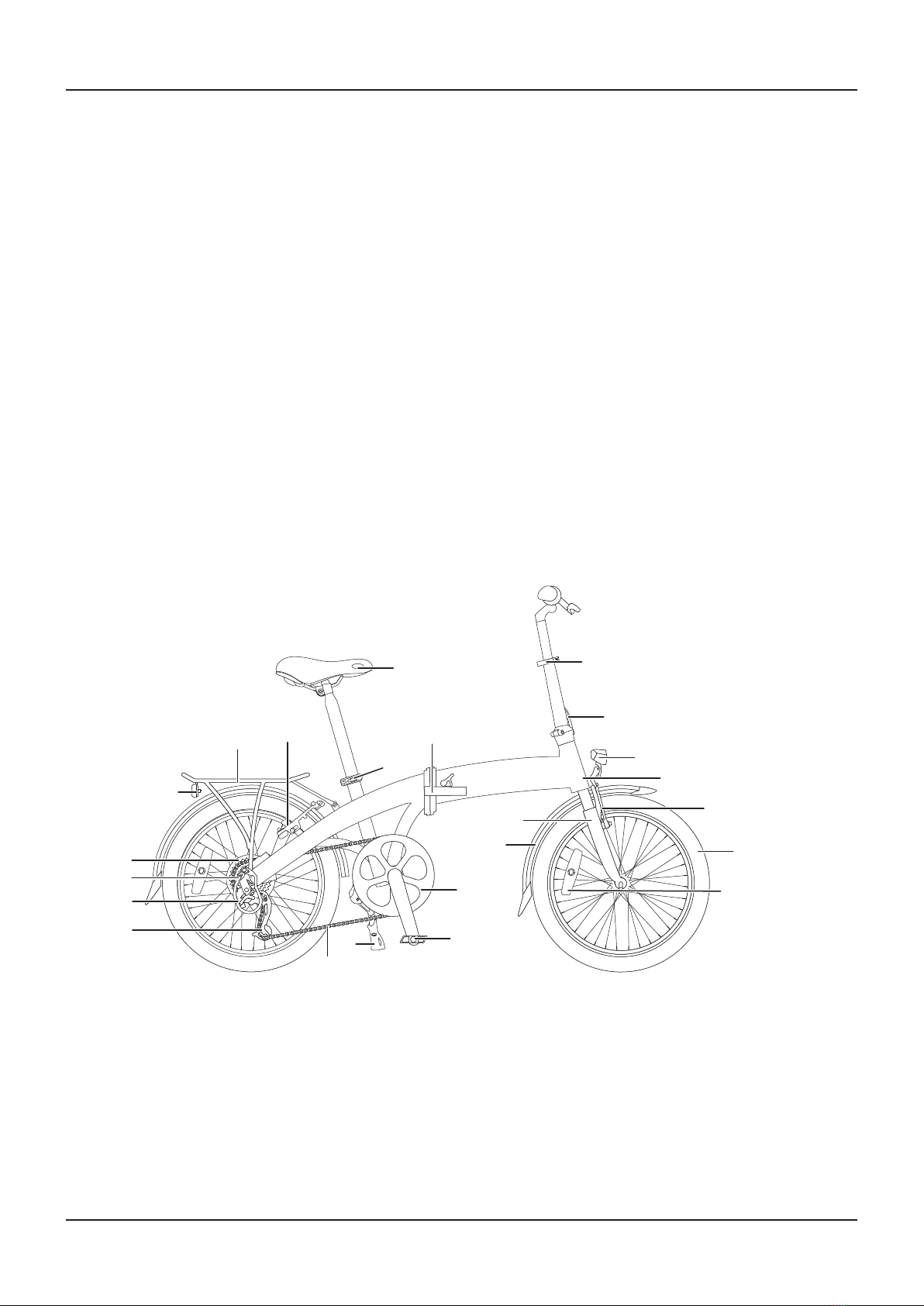
1.4 Bike Components ..................................................................................................................................................... 01
1.5 Range ...................................................................................................................................................................... 02
1.6 Shifting Recommendations ....................................................................................................................................... 02
2 SAFETY
2.1 Battery & Charger ..................................................................................................................................................... 03
2.2 Bike Usage ............................................................................................................................................................... 03
2.3 Keys ......................................................................................................................................................................... 05
3. INSTALLATION AND ADJUSTMENT
3.1 Handlebar and Stem Assembly ................................................................................................................................. 05
3.2 Assembly of the Pedals ............................................................................................................................................ 05
3.3 Unfolding the Frame ................................................................................................................................................. 06
3.4 Seat Position ............................................................................................................................................................ 07
3.5 Saddle Height .......................................................................................................................................................... 08
3.6 Saddle Adjustment ................................................................................................................................................... 08
3.7 Brakes ...................................................................................................................................................................... 08
3.8 Shifter and Derailleur Adjustment ............................................................................................................................. 10
4 E-PARTS OVERVIEW
4.1 Explanation .............................................................................................................................................................. 11
4.2 Battery & Charger .................................................................................................................................................... 11
4.2.1 Overview ............................................................................................................................................................... 11
4.2.2 General Remarks .................................................................................................................................................. 12
4.2.3 Installing and Removing the Battery ...................................................................................................................... 12
4.2.4 Charging ............................................................................................................................................................... 12
4.2.5 Usage .................................................................................................................................................................... 13
4.2.6 Storage .................................................................................................................................................................. 14
5. DISPLAY .................................................................................................................................................................... 15
6. RECOMMENDATIONS AND MAINTENANCE
6.1 General Requirements ............................................................................................................................................. 23
6.2 Maintenance Schedule ............................................................................................................................................. 23
6.3 Troubleshooting ........................................................................................................................................................ 25
6.4 Definition of Tampering and Recommendations ........................................................................................................ 26
7. TECHNICAL DATA .................................................................................................................................................... 27
8. WARRANTY .............................................................................................................................................................. 27

GENERAL
01
NCM LYON
1. GENERAL
1.1 Welcome
We would like to thank you for your purchase of an NCM E-bicycle and welcome you to our fast-growing family of E-bike
enthusiasts. Bicycles offer unparalleled practicality and excitement, and our E-bikes at NCM are supercharged versions of
this amazing invention. As bikes have evolved so have we, standing at the forefront of innovation in E-cycling technology,
aiming to offer something new and thrilling while keeping and promoting the soul of cycling.
1.2 Use of the Manual
We encourage you to read this manual thoroughly before you take your new NCM E-bike for a ride. It is important not to
overlook the safety instructions and explanations of both traditional and non-traditional bike parts, as this will offer you a
general understanding of your new NCM E-bike. This manual is designed to help you get the most out of your E-bike, and
so we have attempted to answer as many of your potential questions as possible. Please take a moment to read through
the various sections before you get in the saddle.
1.3 Service and Technical Support
This manual is intended as a general overview of your new NCM E-bike, and is therefore not an extensive reference. For
technical support, including information about service, maintenance and repairs, please consult your dealer. You can visit
our website (www.ncmbikes.com) for more information about our products and technology, or to find a dealer close to you.
1.4 Bike Components
17
8
7
6
11
10
9
18
14
13
19
20
22
21
23
15
16
1
3
2
12
5
4
1 Rear Light
2 Motor
3 Freewheel
4 Rear Derailleur Protector
5 Rear Derailleur
6 Carrier
7 Rear V Brake
8 Saddle
9 Saddle Quick Release
10 Frame Folding Lever
11 Chain
12 Kickstand
13 Pedal
14 Crankset
15 Mudguard
16 Front Fork
17 Stem Quick Release
18 Stem Folding Lever
19 Front Light
20 Frame Number
21 Front V Brake
22 Tire
23 Wheel Reflector
(different country use different reflector)

HM19G000000
GENERAL
02
NCM LYON
Handlebar Attachments
1 Left Brake Lever
2 Left Grip
3 Display
4 Head Stem
5 7-Speed Revo Shift
6 Right Grip
1
23
4
65
7
8
Frame Number Indicator
1 Frame Number (head tube)
2 Frame Number (sticker)
1.5 Range
The range on one battery charge strongly depends on several conditions, such as (but not limited to):
●Road conditions, such as road surface and slope.
●Weather conditions, such as temperature and wind.
●Bike conditions, such as tire pressure and maintenance level.
●Bike usage, such as acceleration, shifting, and motor assistance level.
●Weight of rider and cargo.
●Number of charge and discharge cycles.
1.6 Shifting Recommendations
For improved range, we advise shifting according to speed. For setting off and traveling at low speeds, a lower gear is best.
At higher speeds a higher gear should be chosen. Releasing pressure from the pedals while shifting will allow for smooth
support and improved range.
●High speed, high gear
●Low speed, low gear
●Reduce pedal pressure when shifting
H
M
1
9
G
0
0
0
0
0
0
1
2
7 Right Brake Lever
8 Bell

SAFETY
03
NCM LYON
2. SAFETY
2.1 Battery & Charger
●Keep the battery and charger away from water and heat sources.
●Do not connect positive and negative terminals.
●Keep the battery away from children and pets.
●Use the battery and charger only for their intended purpose as part of your E-bike.
●Do not cover the battery and charger, place objects on top of it or rest objects against it.
●Do not subject the battery and charger to shocks (e.g. by dropping).
●Stop the charging procedure immediately if you notice anything unusual.
In the unlikely event of the battery catching fire, DO NOT attempt to put it out with water. Use sand or another fire retard-
ant instead and call emergency services immediately.
Avoid contact with the battery and charger during the charging procedure; the charger heats up considerably.
Please take note of the additional information on the rear of the battery case.
2.2 Bike Usage
Try all settings on the E-bike and become accustomed to their various results in a safe and controlled environment before
you try riding the bike on the open road. Bicycles with pedaling support may handle somewhat differently depending on
the settings being used.
IMPORTANT SAFETY INFORMATION
1. Always wear a helmet while riding. Make sure your helmet complies with local laws.
2. Keep body parts and other objects away from moving bicycle parts which may cause you harm, such as the wheels and
chain. Do not rest any objects on the battery or motor. Do not impede the drivetrain in any way.
3. Always wear shoes that will stay on your feet and will grip the pedals securely. Never ride barefoot or when wearing
sandals.
4. Be thoroughly familiar with the controls of your bike.
5. Wear bright, visible clothing that is not so loose that it may accidentally catch on moving parts of the bike or be snagged
by objects at the side of the road or trail.
6. Do not jump with your bike. Jumping with a bike puts incredible stress on most components, such as the spokes and
pedals. One of the most vulnerable parts to jumping-related damage is your front fork. Riders who insist on jumping a bike
risk serious damage to the bike as well as to themselves.
7. Be mindful of your speed and keep it at a level which is consistent with conditions. Always keep in mind that there is a
direct relationship between speed and control, and also between speed and component stress.
8. Always follow local traffic laws.
9. Never ride while under the influence of alcohol, medication or drugs.
10. If you suffer from any health conditions, please consult your doctor before riding.
11. Never endanger yourself or others through reckless riding.
12. Please keep in mind that braking distance increases with imperfect road conditions, such as gravel or wet surfaces.
13. Please check the cable routing of the brakes before cycling. Ensure that both brakes are operational and in good
condition.

SAFETY
04
NCM LYON
WARNING:
●Please do not touch the hot surfaces after heavy use, such as the disc brake rotor or V-brake rim side edge.
●When folding out the kickstand, always ensure that the stand is secure and that the base is solid, so that a fall of
the bicycle is prevented.
●Please follow local laws regarding age restrictions for cyclists.
It is customary for countries with right-hand traffic to have the front brake on the left-hand brake lever and the rear brake
on the right-hand lever. The opposite is generally true for countries with left-hand traffic. The table below shows several
examples.
Country
Austria
Brazil
Canada
Denmark
France
Germany
Italy
Netherlands
Portugal
Poland
Spain
South Korea
Switzerland
Russia
USA
Country
Left lever controls front brake,
Right lever controls rear brake
Left lever controls rear brake,
Right lever control front brake
Australia
Indonesia
Japan
Hongkong
Malaysia
New Zealand
Singapore
UK
Cable Routing Cable Routing
1

INSTALLATION AND ADJUSTMENT
05
NCM LYON
2.3 Keys
Each NCM E-bike comes with two copies of the battery lock key. Bikes with rim locks are delivered with extra keys (not
the same key as the battery). Onboard charging of the battery will likely lead to infrequent usage of the battery lock key; it
is needed for maintenance and repair, however, so please keep this in mind when storing the key.
●Make sure to always have at least one spare key.
●Keep spare key(s) in a safe place for repairs, maintenance and emergencies.
●Please bring the key when going to your NCM dealer for maintenance or repairs.
3. INSTALLATION AND ADJUSTMENT
3.1 Handlebar and Stem Assembly
Lift the handlebars and plastic cover into place, then press the locking lever to secure the stem.
3.2 Assembly of the Pedals
- Identify your pedals: check the letters on the pedal, "L" or "R".
- The "R" marked pedal is for the right (when facing the forward direction). For attachment to the crank, tighten clockwise.
- The "L" marked pedal is for the left. For attachment, tighten counterclockwise when facing directly.
If the pedal is folded down, simply pull it parallel to the pedal
platform and it will snap into place
To fold the pedal, push the outer part toward the crankarm
and then downward to a perpendicular position with respect
to the pedal platform.
WARNING:
First screw on the pedals by hand, then tighten with tool.

INSTALLATION AND ADJUSTMENT
06
NCM LYON
3.3 Unfolding the Frame
Align the two parts of the frame, pull the lever(2) downward and then close the small lock lever(2) downward to lock the
frame. The lever(2) should require noticeable force to fully close.
Folding the Frame
Pull the small locking lever(1) upward and then open the lever(2), then the bike is now unlocked and can be folded for
storage or transport.
1
2

INSTALLATION AND ADJUSTMENT
07
NCM LYON
3.4 Seat Position
To enable comfortable, fatigue-free and safe riding, the saddle and handlebar height should be adjusted to the body size
of the rider.
The saddle height is correct if the leg is near full extension while the foot is resting flat on the pedal in the bottom position
of the crank cycle. The toes must still be able to touch the ground comfortably.
Too low Too high
Optimal

INSTALLATION AND ADJUSTMENT
08
NCM LYON
3.5 Saddle Height
The quick-release lever must require noticeable effort to put into fully closed position to prevent any undesired movement
while riding.
3.6 Saddle Adjustment
The saddle can also be tilted and adjusted in the forward/back
direction.
-Loosen the bolt at the bottom (4).
-Adjust the saddle tilt by pressing down on the front or rear of the
saddle
-Move the saddle forward or backward to adjust for arm/torso length
and desired riding position.
Tighten the bolt (4) to secure the saddle.
WARNING:
An improperly closed quick release lever can open again or have limited ability to keep the saddle in place. This may
cause the saddle to suddenly drop into the seat tube, potentially leading to serious falls and injury.
WARNING:
To avoid discomfort, the saddle should generally be set as horizontal as possible.
MIN INSERT
There is a minimum insertion line marked on the seat post (Failure
to observe the minimum insertion line can result in serious injury);
please ensure the seat post is always inserted into the seat tube
beyond this line (the line must be inside the seat tube).
-Loosen the quick release lever at the top of the seat tube, deter-
mine the appropriate saddle height and tighten the clamp.
-The clamping force can be adjusted by adjusting the bolt on the
quick release lever.
-The quick release lever must be closed with considerable counter
pressure.
4
3.7 Brakes
3.7.1 General
In most countries, bicycles are made so that the left brake-lever controls the front-wheel brake; to change this, please
contact your dealer for help, Keep in mind Section 2- Important safety information.
If your bicycle has two hand brakes, apply both brakes at the same time for optimal stopping distance.

INSTALLATION AND ADJUSTMENT
09
NCM LYON
3.7.2 Brake Adjustment
Rim brakes(V-brakes)
Brake modulator
The brakes are equipped with a brake modulator, or “Power modulator.” This device includes a small spring in the brake
tube. As you squeeze the brake lever, you must compress the spring before you can apply full braking power to the rim.
This changes the way the brake feels, makes the application of stopping force more gradual, and also makes the adjust-
ment somewhat more sensitive.
WARNING:
Overuse or incorrect use of a front-wheel brake can cause the rear wheel to lift off the ground, resulting in decreased
control of the bike or even flipping the bike and rider in the forward direction; this can lead to serious injury and bicycle
damage. Be careful when applying the front brake, and avoid using it without also using the rear brake. Ideally, both
brakes should be applied at the same time, with the rider moving rearward on the bicycle depending on the amount of
braking pressure applied.
WARNING:
Brake-pads remove rim material when you apply the brake. If the brakes remove too much material over time, the rim can
become weak and break, decrease your control, and cause you to fall. Regularly check your rims. Replace a rim that is
worn.
Rim wear indicator: shallow groove in brake track on aluminum rim
1. Brake Modulator
2. barrel-adjuster
2
1

NCM LYON
10
INSTALLATION AND ADJUSTMENT
To adjust the alignment of the brake pads on a rim brake
1. Loosen the brake-pad fixing bolt.
2. Align the brake pads as shown in the figure above. Tighten the brake-pad fixing bolts.
3. After you adjust the brake, test it by pulling the lever. Make sure the cable does not slide through the cable clamp, the
brake pads engage the rim at ninety-degree angles, and the brake pads do not touch the tire.
To adjust the clearance between the brake pads and the rim
1. Turn the barrel-adjuster located on the brake lever.
• To increase the clearance between the brake pads and rim, turn the
barrel-adjuster clockwise.
• To decrease the clearance, turn the barrel-adjuster counter clock-
wise.
2. If the brake pads cannot be adjusted correctly with the
barrel-adjuster, further work is required:
• Loosen the cable-clamp bolt, adjust the cable and tighten the bolt
again.
• Release the cable slightly to increase clearance.
• Tighten the cable to decrease clearance.
• Re-adjust the brake-pad alignment, or take the bicycle to your dealer.
3.8 Shifter and Derailleur Adjustment
Rear Derailleur Adjustment
Step 1: Make sure the rear derailleur is shifted all the way down to the
smallest cog.
Step 2: Turn your barrel-adjuster all the way tight so that you have
room to adjust it later.
Step 3: Adjust the high limit by rotating the screw marked "H" on your
derailleur so that it lines up with that smallest cog.
Step 4: Tighten the tension in your cable by unscrewing the cable
anchor, pulling the cable tight, and screwing the anchor back on tight.
Step 5: Shift your rear derailleur to the 4th or 5th cog.
Step 6: To adjust the index, turn your barrel-adjuster so that the
derailleur pulley lines up underneath the correct (chosen) cog. With a
Shimano rear derailleur, you want to line up the pulley slightly inboard
of the cog. Perform some practice shifts to make sure it is adjusted
properly.
Step 7: Shift your rear derailleur to the largest cog.
Step 8: Adjust the low limit by rotating the screw marked "L" on your
derailleur so that it lines up with the largest cog.
Step 9: Adjust the B-tension screw so that the pulley on the rear
derailleur is as close to the largest cog on the cassette as possible
without dragging.
1.Cable-clamp bolt
2.Pad-clamp bolt
3.Center-adjust screw
4.Arm-clamp bolt
H
L
1
3
4
2

E-PARTS OVERVIEW
11
NCM LYON
5
4
3
1
2
4 E-PARTS OVERVIEW
4.1 Explanation
NCM E-bikes are equipped with components that work together to give you a smooth, powerful and effortless riding feel.
Our pedal-assist system consists of the following:
Battery
NCM E-bikes’ integrated lithium-ion battery packs are some of the highest capacity packs available on the market, with the
NCM Lyon model storing up to 288Wh of energy. The packs consist of high-density Panasonic cells, meaning that our
designs remain sleek and light without any sacrifices to battery capacity. Furthermore, most of our designs boast a built-in
USB port, perfect for charging your cell phone or other small electronic devices on the go.
Motor Powered by BAFANG
With a reliable, compact but powerful 250W Bafang motor, you will always have the required assistance on hand when you
want it. Delivering a smooth and quiet ride at all assistance levels, this motor is perfect for helping the rider navigate busy
city streets as well as peaceful parks and nature areas.
Display
The Das-Kit control panel gives the rider full command over the electric system, and its simple setup provides all the
information you may need about your E-bike at the quick touch of a button, allowing you to spend more time enjoying the
world around you. The display provides the following information:
●Battery level indicator
●Support level indicator
●General indicators: speed, distance etc.
When using the brake with the brake sensor (the brake lever controlling the front brake), the sensors inside cause the
engine’s support to stop immediately. Engaging the rear brake will automatically stop the motor’s assistance in all cases.
Another sensor, within the crankset, also serves to stop the motor when the rider stops pedaling.
The bike can also be used without electrical support from the motor; by setting the support level to 0, the E-bike will
behave like a traditional bicycle. An empty battery will not render your bike unusable.
4.2 Battery & Charger
4.2.1 Overview
1 Battery Lock
2 Battery
3 USB Port(output: 5V 700mA)
4 Power Switch
5 Charging Plug
WARNING: (Sticker on the battery)
Please make sure that the battery is locked before you use it.

E-PARTS OVERVIEW
12
NCM LYON
4.2.4 Charging
●Charging at temperatures below 0°C or above 60°C (32°F~140 °F) can cause the battery to charge insufficiently and
can be harmful to the life of the battery.
●During charging, the charger’s LED light will be continuously red.
●Charging is completed when the charger’s LED turns green.
4.2.2 General Remarks
●Stop charging the battery immediately if you notice anything unusual, such as smoke or a strange smell; take out the
battery and store it outside of the house, then take the battery to an authorized NCM dealer or experienced technician for
service or replacement.
●In the unlikely case that the battery catches fire, do NOT attempt to put it out with water. Use sand or another fire
retardant instead and call emergency services immediately.
4.2.3 Installing and Removing the Battery
The battery (1) is secured with a lock.
-Unlock the battery (1) and pull it out.
-Insert the battery (1) into the frame until it stops.
-Ensure the battery is well install and then take off the key.
A AC socket (100~240V) (type will vary)
B Charger
C Charging Indicator
D Charging Socket
C
B
D
A
1
● Do not use or charge the battery under high temperature.
● Do not short circuit the positive(+) and negative(-) connectors of the battery.
● Do not immerse the battery into water or acid liquid. Do not put the battery near fire.
● Do not disassemble the battery case.
● Please store the battery in a clean and dry environment and charge the battery for two hours every three months when
not use for long time.
● Please charge the battery with the specified charger.
ATTENTION: (Sticker on the battery)

E-PARTS OVERVIEW
13
NCM LYON
Charging battery outside the bike
1. Unfold the frame first.
2. Take out the battery.
3. Connect the charger to the battery.
4. Connect the charger to an AC outlet.
5. Charging procedure can be stopped at any time.
6. Disconnect the charger from the AC outlet first and then from the battery.
7. Reinstall the battery and ensure that it is correctly aligned at the bottom.
8. Push down on the top of the battery until you notice a ‘click’ in order to ensure that the battery is properly secured.
9. Pull out the key.
10. Your NCM E-bike is ready for use.
Charging battery inside the bike
1. Connect the charger to the battery.
2. Connect the charger to an AC outlet.
3. Charging procedure can be stopped at any time.
4. Disconnect the charger from the AC outlet first and then from the battery.
5. Your NCM E-bike is ready for use.
4.2.5 Usage
Make sure you activate the battery by switch on the power button at the right side of cycling ward.
Turn on the display that is located on the handlebar, select the desired support level and begin pedaling.
You will notice that the motor starts as soon as you begin moving the pedals.
The charging time will be around 4 hours per one time. Please do not charge the battery for more than 10 hours at a time
(the battery will be fully charged much sooner).
A fall resulting in serious injury may occur if the following points are not observed:
1. Before you set off, hold the handlebar straight.
2. To get familiar with the bike and riding feel, begin with the motor turned off (you can set the support level to 0 on the
display). Do not switch the motor on until you are in motion.
3. Do not use the pedals to start moving until a safe and comfortable sitting position has been taken.
4. When navigating a tight curve or corner, apply the brake slightly to temporarily disable the motor and allow for a safe
turn.
The bicycle can be operated with the auxiliary drive support of the motor and without it. An empty battery will NOT render
the bicycle unusable.
When using the motor for pedal assistance, proceed as if using a normal bicycle; pressing down on the pedals will activate
the motor and further accelerate the bike.

NCM LYON
E-PARTS OVERVIEW
14
Level of Support
If the bicycle remains stationary with the display and auxiliary drive on, it will turn off after about 10 minutes along with the
battery capacity indicator.
During longer hill climbs, the motor can become so warm that the current is reduced via the temperature sensor inside,
causing the level of support from the motor to decrease; the rider may need to increase physical pedal support to maintain
speed.
4.2.6 Storage
If the bike is not in use for a period of longer than one month, it is best to store the battery:
●At 40%-60% of its capacity, charged once a month for 30 minutes.
●Detached from the bike.
●At temperatures between 0°C and 40°C.
If not in use, the battery should be checked once a month and should have at least one LED light blinking, indicating
remaining charge. Charge the battery if necessary.
It is important to charge the battery every three months (for one or two hours) at the minimum. Failing to do so can cause
harm to the battery and could result in the warranty of the battery becoming void.

NCM LYON DISPLAY
15
5 Display
5.1 The Buttons
There are three buttons on the display: “M”, “+” and “-”.
“M” represents MODE/ON/OFF.
“+” represents UP. “-” represents DOWN.

DISPLAY NCM LYON
16
M
5.2 Display Functions
5.2.1 FUNCTION SUMMARY
1. Switch
M
UP
4.Speed display
5.Backlight indicator
6.Walk mode
7.Assist level selection
8.Error code indicator
9.SET operation
10.Distance indicator
2.Battery indicator
3.Auto sleep after 5 minutes
DOWN
MODE/ON/OFF

DISPLAY
NCM LYON
17
5.2.2 FULL VIEW AREA
5.2.3 NORMAL VIEW AREA
The normal view area of the L6 is shown below. It indicates the remaining battery capacity, speed, PAS, and distance
traveled.
5.3 Normal Operation
5.3.1 ON/OFF
Press M to activate the display. With the display on, press M for 2 seconds to turn off power. With the display off, there is
no battery power consumption.
The leakage current is no more than 2µA.
※ The panel will automatically power off when speed is 0 km/h for 5 minutes.
M

NCM LYON
18
DISPLAY
5.3.2 CURRENT DISPLAY
The current indicator shows the present discharging current of the controller: each segment is 2A; six segments are
>=12A (The bar graph shows in real time the output power of the motor. 1 bar – low power, all bars – full power.)
5.3.3 SPEED DISPLAY
The top-right of the display indicates the current riding speed of the E-bike. The unit of measure is factory set to KM/H; if
you want to change the display to MPH, please contact your dealer or online service technician.
5.3.4 BACKLIGHT INDICATOR
With the power on, press UP (+) for 2 seconds to turn on the backlight. Press it for 2 seconds again to turn off the back-
light.
5.3.5 WALK MODE
Hold DOWN (-) for 2 seconds to enter the power-assisted walk mode. When the AUTO icon is lit, the E-bike will travel at
6km/h without the need for the rider to pedal. Assisted walk mode will cease when the “-“ button is no longer being
pressed.
5.3.6 ASSIST LEVEL SELECTION
Press UP (+) or DOWN (-) to change the PAS level and thus change the power output of the motor. The default mode is
PAS 1 and assistance ranges from level 0 to level 6. Level 0 provides no assistance from the motor. The levels are
customizable.
Table of contents
Other NCM Bicycle manuals